Fundamental EIGRP Concepts - IGP Routing Protocols - CCNP Routing and Switching ROUTE 300-101 Official Cert Guide (2015)
CCNP Routing and Switching ROUTE 300-101 Official Cert Guide (2015)
Part II. IGP Routing Protocols
Chapter 4. Fundamental EIGRP Concepts
This chapter covers the following topics that you need to master for the CCNP ROUTE exam:
EIGRP Fundamentals: This section reviews the EIGRP concepts, configuration, and verification commands covered in the CCNA curriculum.
EIGRP Neighborships: This section discusses a variety of features that impact when a router attempts to form EIGRP neighbor relationships (neighborships), what must be true for those neighborships to work, and what might prevent those neighborships.
Neighborships over WANs: This section examines the typical usage of EIGRP neighborships over various types of WAN technologies.
Enhanced Interior Gateway Routing Protocol (EIGRP) is configured with a few relatively simple commands. In fact, for most any size network, you could go to every router, enter the router eigrp 1 command, followed by one or more networknet-id subcommands (one for each classful network to which the router is connected), and EIGRP would likely work, and work very well, with no other configuration.
In spite of that apparent simplicity, here you sit beginning the first of four chapters of EIGRP coverage in this book. Many reasons exist for the amount of EIGRP material included here. First, EIGRP includes many optional configuration features that you need to both understand and master for the CCNP ROUTE exam. Many of these features require a solid understanding of EIGRP internals as well—a topic that can be conveniently ignored if you just do the minimal configuration, but something very important to planning, implementing, and optimizing a medium/large enterprise network.
Another reason for the depth of EIGRP coverage in this book is a fundamental change in the philosophy of the CCNP exams, as compared with earlier CCNP exam versions. Cisco has increased the focus on planning for the implementation and verification of new network designs. The bar has been raised, and in a way that is consistent with typical engineering jobs. Not only do you need to understand all the EIGRP features, but you also need to be able to look at a set of design requirements, and from that decide which EIGRP configuration settings could be useful—and which are not useful. You must also be able to direct others as to what verification steps would tell them if the implementation worked or not, rather than just relying on typing a ? and looking around for that little piece of information you know exists somewhere.
This chapter begins with the “EIGRP Fundamentals” section, which is a review of the core prerequisite facts about EIGRP. Following the review, the chapter examines EIGRP neighbor relationships, including a variety of configuration commands that impact neighbor relationships, and the verification commands that you can use to confirm how well EIGRP neighbors work.
“Do I Know This Already?” Quiz
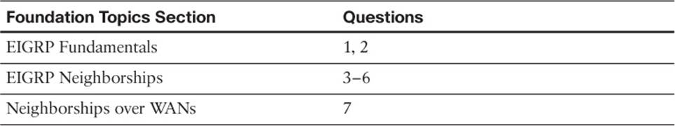
The “Do I Know This Already?” quiz enables you to assess whether you should read the entire chapter. If you miss no more than one of these seven self-assessment questions, you might want to move ahead to the “Exam Preparation Tasks” section. Table 4-1 lists the major headings in this chapter and the “Do I Know This Already?” quiz questions covering the material in those headings so that you can assess your knowledge of these specific areas. The answers to the “Do I Know This Already?” quiz appear in Appendix A.
Table 4-1“Do I Know This Already?” Foundation Topics Section-to-Question Mapping
1. A router has been configured with the commands router eigrp 9 and network 172.16.1.0 0.0.0.255. No other EIGRP-related commands have been configured. The answers list the IP addresses that could be assigned to this router’s Fa0/0 interface. Which answers list an IP address/prefix length that would cause the router to enable EIGRP on Fa0/0? (Choose two answers.)
a. 172.16.0.1/23
b. 172.16.1.1/26
c. 172.16.1.1/24
d. 172.16.0.255/23
e. None of the other answers are correct.
2. Router R1 has working interfaces S0/0, S0/1, and S0/2, with IP address/prefix combinations of 10.10.10.1/24, 10.10.11.2/24, and 10.10.12.3/22. R1’s configuration includes the commands router eigrp 9 and network 10.0.0.0. The show ip eigrp interfaces command lists S0/0 and S0/1 in the command output, but not S0/2. Which answer gives a possible reason for the omission?
a. R1 has EIGRP neighbors reachable through S0/0 and S0/1, but not through S0/2, so it is not included.
b. S0/2 might currently be in a state other than up/up.
c. The network 10.0.0.0 command requires the use of mask 255.0.0.0 because of EIGRP being classful by default.
d. S0/2 might be configured as a passive interface.
3. Routers R1 and R2 are EIGRP neighbors using their Fa0/0 interfaces, respectively. An engineer adds the ip hello-interval eigrp 9 6 command to R1’s Fa0/0 configuration. Which of the following is true regarding the results from this change?
a. The show ip eigrp neighbors command on R1 lists the revised Hello timer.
b. The show ip eigrp interfaces command on R1 lists the revised Hello timer.
c. The R1-R2 neighborship fails because of a Hello timer mismatch.
d. The show ip eigrp interfaces detail command on R1 lists the revised Hello timer.
4. Router R1 has been configured with the commands router eigrp 9 and network 172.16.2.0 0.0.0.255, with no other current EIGRP configuration. R1’s (working) Fa0/0 interface has been configured with IP address 172.16.2.2/26. R1 has found three EIGRP neighbors reachable through interface Fa0/0, including the router with IP address 172.16.2.20. When the engineer attempts to add the neighbor 172.16.2.20 fa0/0 command in EIGRP configuration mode, which of the following occurs?
a. Fa0/0 fails.
b. The command is rejected.
c. The existing three neighbors fail.
d. The neighborship with 172.16.2.20 fails and then reestablishes.
e. None of the other answers is correct.
5. Which of the following settings could prevent two potential EIGRP neighbors from becoming neighbors? (Choose two answers.)
a. The interface used by one router to connect to the other router is passive in the EIGRP process.
b. Duplicate EIGRP router IDs.
c. Mismatched Hold Timers.
d. IP addresses of 10.1.1.1/24 and 10.2.2.2/24, respectively.
6. An engineer has added the following configuration snippet to an implementation planning document. The configuration will be added to Router R1, whose Fa0/0 interface connects to a LAN to which Routers R2 and R3 also connect. R2 and R3 are already EIGRP neighbors with each other. Assuming that the snippet shows all commands on R1 related to EIGRP authentication, which answer lists an appropriate comment to be made during the implementation plan peer review?
key chain fred key 3 key-string whehew interface fa0/0 ip authentication key-chain eigrp 9 fred
a. The configuration is missing one authentication-related configuration command.
b. The configuration is missing two authentication-related configuration commands.
c. Authentication type 9 is not supported; type 5 should be used instead.
d. The key numbers must begin with key 1, so change the key 3 command to key 1.
7. A company has a Frame Relay WAN with one central-site router and 100 branch office routers. A partial mesh of PVCs exists: one PVC between the central site and each of the 100 branch routers. Which of the following could be true about the number of EIGRP neighborships?
a. A partial mesh totaling 100: one between the central-site router and each of the 100 branches.
b. A full mesh — (101 * 100) / 2 = 5050 — One neighborship between each pair of routers.
c. 101 — One between each router (including the central site) and its nearby PE router.
d. None of the answers is correct.
Foundation Topics
EIGRP Fundamentals
All the CCNP exams consider CCNA materials as prerequisites. So this book also assumes that the reader is already familiar with CCNA topics. However, the CCNP exams do test on features that overlap with CCNA. Additionally, most people forget some details along the way. Therefore, this section reviews the CCNA-level topics as a brief refresher.
To that end, this section begins with a review of EIGRP configuration using only the router eigrp and network commands. Following that, the next section details the key fields used to verify that EIGRP is working. Finally, the last part of this introduction summarizes the basic EIGRP internals behind this initial simple example.
Configuration Review
Cisco IOS uses the router eigrpasn command (where asn is an autonomous system number [ASN]), plus one or more networknet-id wildcard-mask subcommands, to enable EIGRP on the router and on router interfaces. The rules for these commands are as follows:
1. Neighboring routers’ router eigrpasn commands must be configured with the same ASN parameter to become neighbors.
2. Cisco IOS enables only EIGRP on interfaces matched by an EIGRP network command. When enabled, the router does the following:
a. Attempts to discover EIGRP neighbors on that interface by sending multicast EIGRP Hello messages
b. Advertises to other neighbors about the subnet connected to the interface
3. If no wildcard mask is configured on the EIGRP network command, the command’s single parameter should be a classful network number (in other words, a class A, B, or C network number).
4. If no wildcard mask is configured on the EIGRP network command, the command enables EIGRP on all of that router’s interfaces directly connected to the configured classful network.
5. If the network command includes a wildcard mask, the router performs access control list (ACL) logic when comparing the net-id configured in the network command with each interface’s IP address, using the configured wildcard mask as an ACL wildcard mask.
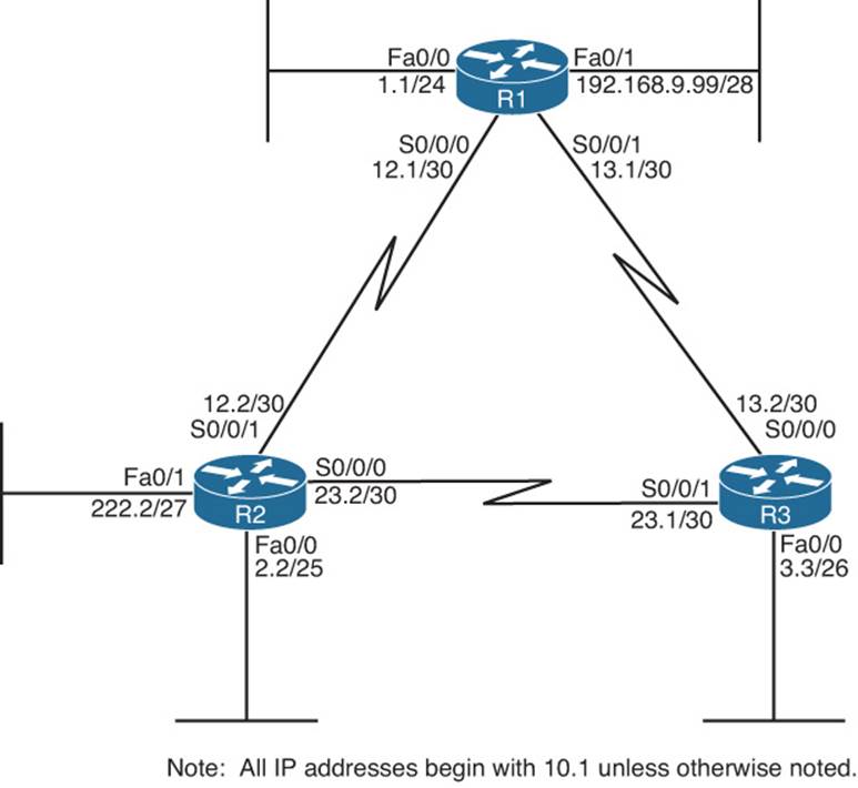
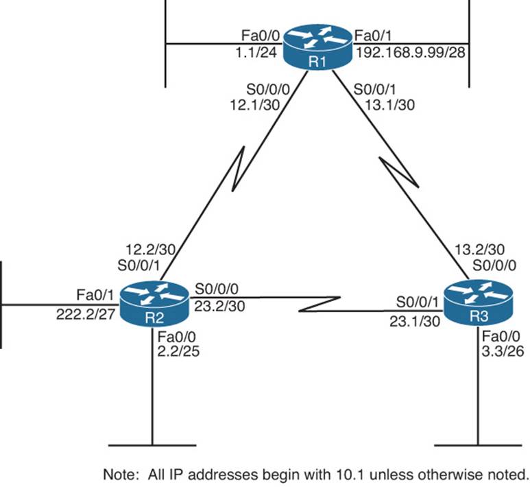
Example 4-1 shows a sample configuration for each router in Figure 4-1, with several variations in the network commands to make the details in the preceding list more obvious.
Figure 4-1Three-Router Internetwork
Example 4-1EIGRP Configuration on Routers R1, R2, and R3
! On Router R1:
! On Router R2:
! On Router R3:
First, note that all three routers use the router eigrp 1 command, so all three routers’ ASN values match.
Next, consider the two network commands on R1. The network 10.0.0.0 command, without a wildcard-mask parameter, means that R1 matches all interfaces in class A network 10.0.0.0—which in this case means R1’s Fa0/0, S0/0/0, and S0/0/1 interfaces. The network 192.168.9.0command, again without a wildcard mask, matches interface Fa0/1.
On R2, the network 10.1.0.0 0.0.31.255 command requires a little more thought. The router uses the 0.0.31.255 value—the wildcard (WC) mask—just like an ACL WC mask. Cisco IOS compares the 10.1.0.0 value with each interface IP address, but only for the bit positions for which the WC mask lists a binary 0. For example, 0.0.31.255 represents 19 binary 0s, followed by 13 binary 1s. So, R2 would compare the first 19 bits of 10.1.0.0 with the first 19 bits of each interface’s IP address.
Two features of the mechanics of the network command require a little extra attention. First, Cisco IOS might convert the address portion of the networkaddress wc-mask command before putting the command into the running config. Just as Cisco IOS does for the address/WC mask combinations for the access-list command, Cisco IOS inverts the WC mask and then performs a Boolean AND of the address and mask. For example, if you type the network 10.1.1.1 0.0.255.255 command, Cisco IOS inverts the WC mask (to 255.255.0.0) and ANDs this value with 10.1.1.1, resulting in 10.1.0.0. As a result, Cisco IOS stores the command network 10.1.0.0 0.0.255.255.
The second feature is that when you know for sure the values in the network command, you can easily find the range of interface addresses that match the address/WC mask combination in the network command. The low end of the range is the address as listed in the network command. To find the high end of the range, just add the address and WC mask together. For example, the network 10.1.0.0 0.0.31.255 command has a range of 10.1.0.0 through 10.1.31.255.
Finally, on R3, the network 10.1.0.0 0.0.255.255 command tells R3 to enable EIGRP on all interfaces whose IP addresses begin with 10.1, which includes all three interfaces on R3, as shown in Figure 4-1.
Taking a step back from the details, this config has enabled EIGRP, with ASN 1, on all three routers, and on all interfaces shown in Figure 4-1—except one interface. R2’s Fa0/1 interface is not matched by any network commands on R2. So, EIGRP is not enabled on that interface. The next section reviews the commands that can be used to confirm that EIGRP is enabled, the interfaces on which it is enabled, the neighbor relationships that have been formed, and which EIGRP routes have been advertised and learned.
Verification Review
Even before starting to configure the routers, an engineer first considers all requirements. Those requirements lead to a design, which in turn leads to a chosen set of configuration commands. Then, the verification process that follows must consider the design requirements. The goal of verification is to determine that the internetwork works as designed, not just that some EIGRP routes have been learned.
For the purposes of this section, assume that the only design goal for the internetwork shown in Figure 4-1 is that EIGRP be used so that all routers have routes to reach all subnets shown in the figure.
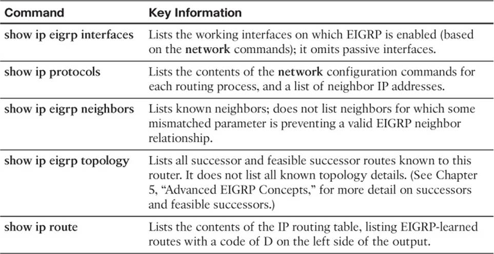
To verify such a simple design, an engineer should start by confirming on which interfaces EIGRP has been enabled on each router. The next step should be to determine whether the EIGRP neighbor relationships that should occur are indeed up and working. Then, the EIGRP topology table should be examined to confirm that there is at least one entry for each subnet or network in the design. Finally, the IP routes on each router should be examined, confirming that all routes are known. To that end, Table 4-2 summarizes five key show commands that provide the information to answer these questions.
Table 4-2Key EIGRP Verification Commands
Note
The following table mentions some information that is covered later in this chapter (passive interfaces) or in other chapters (successor/feasible successors).
Example 4-2 shows samples of each command listed in Table 4-2. Note that the output highlights various samples of items that should be verified: the interfaces on which EIGRP is enabled, the known neighbors, the subnets in the topology table, and the EIGRP routes.
Example 4-2EIGRP Verification on Routers R1, R2, and R3
! On Router R1:
! On Router R2:
! On Router R3:
! On Router R2:
! On Router R3:
To verify the interfaces on which EIGRP is enabled, both the show ip eigrp interfaces command (shown on R1) and the show ip protocols command (shown on R2) list the information. For this example, look at the list of interfaces in R2’s show ip protocols command output: S0/0/0, S0/0/1, and FA0/0 are listed, but Fa0/1—unmatched by any of R2’s network commands—is not.
In this design, each router should form a neighbor relationship with the other two routers, in each case over a point-to-point serial link. The show ip eigrp neighbors command (on R3) confirms R3’s neighbors.
Finally, one design goal was for all routers to have routes for all subnets/networks. You could move on to the show ip route command or first look for all prefixes in the show ip eigrp topology command. With relatively general requirements, just looking at the IP routing table is fine. The example highlights R3’s topology data and IP route for subnet 10.1.1.0/24. Of more interest might be the fact that the show ip route command output on R3 lists all subnet/network numbers except one: subnet 10.1.222.0/27. This subnet exists off R2’s Fa0/1 interface (as seen in Figure 4-1), which is the interface on which EIGRP has not yet been enabled.
Internals Review
To complete the review of prerequisite CCNA-level EIGRP knowledge, this section looks at a few of the internals of EIGRP. Some of the facts listed here simply need to be memorized, whereas other topics will be discussed in more detail later.
EIGRP follows three general steps to add routes to the IP routing table, as follows:
Step 1. Neighbor discovery: EIGRP routers send Hello messages to discover potential neighboring EIGRP routers and perform basic parameter checks to determine which routers should become neighbors.
Step 2. Topology exchange: Neighbors exchange full topology updates when the neighbor relationship comes up, and then only partial updates as needed based on changes to the network topology.
Step 3. Choosing routes: Each router analyzes its respective EIGRP topology table, choosing the lowest-metric route to reach each subnet.
Because the majority of the rest of this chapter examines EIGRP neighborships, this review section skips any discussion of EIGRP neighbors, instead focusing on topology exchange and route selection.
Exchanging Topology Information
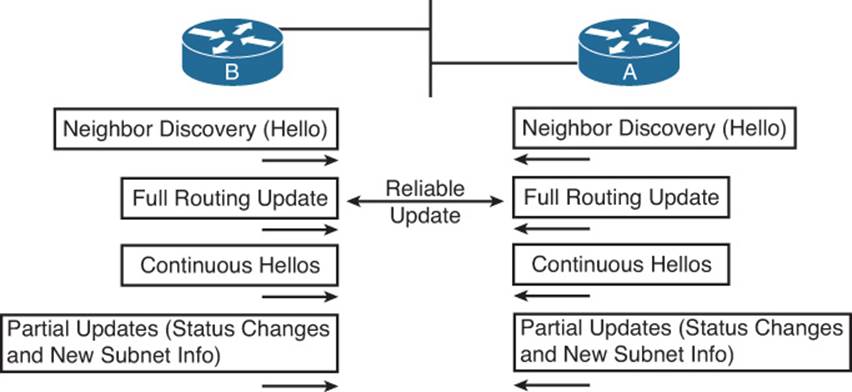
First, the EIGRP neighbor table lists the neighboring routers. Second, the EIGRP topology table holds all the topology information learned from EIGRP neighbors. Finally, EIGRP chooses the best IP routes, and those routes become candidates to be injected into the IP routing table. (Table 4-2, earlier in this chapter, lists the show commands that can be used to examine these tables.) EIGRP routers follow the process shown in Figure 4-2 to build the necessary information in these tables, with the end goal of populating the IP routing table.
Figure 4-2EIGRP Discovery and Update Process
EIGRP uses Update messages to send topology information to neighbors. These Update messages can be sent to multicast IP address 224.0.0.10 if the sending router needs to update multiple routers on the same subnet. Unlike OSPF, there is no concept of a designated router (DR) or backup designated router (BDR), but the use of multicast packets on LANs allows EIGRP to exchange routing information with all neighbors on the LAN efficiently.
The update messages are sent using the Reliable Transport Protocol (RTP). The significance of RTP is that, like OSPF, EIGRP resends routing updates that are lost in transit. By using RTP to guarantee delivery of the EIGRP messages, EIGRP can better avoid loops.
Note
The acronym RTP also refers to a different protocol, Real-time Transport Protocol (RTP), which is used to transmit voice and video IP packets.
Neighbors use both full routing updates and partial updates, as depicted in Figure 4-2. A full update means that a router sends information about all known routes, whereas a partial update includes only information about recently changed routes. Full updates occur when neighbors first come up. After that, the neighbors send only partial updates in reaction to changes to a route.
Calculating the Best Routes for the Routing Table
EIGRP topology information includes the subnet number and mask, along with the components of the EIGRP composite metric. Each router then calculates an integer metric for each route, using the individual values of the EIGRP metric components listed in the EIGRP topology database. By default, EIGRP only uses the bandwidth and delay settings when calculating the metric. Optionally, the calculation can also include interface load and interface reliability, although Cisco recommends against using either.
Note
Past documents and books often stated that EIGRP, and its predecessor IGRP, also could use Maximum Transmission Unit (MTU) as a part of the metric. However, MTU size is intended to be a tiebreaker if two paths have equal metrics but different MTU sizes. In such a case, the path with the higher MTU is selected. So, while MTU size is listed in EIGRP Update messages, it is not directly used in metric calculations.
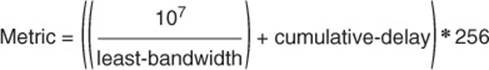
EIGRP calculates the metric for each possible route by inserting the values of the composite metric into a formula. If the choice is made to just use the default parameters of bandwidth and delay, the formula is as follows:
In this formula, the term least-bandwidth represents the lowest-bandwidth link in the route, using a unit of kilobits per second. For example, if the slowest link in a route is a 10-Mbps Ethernet link, the first part of the formula is 107 / 104, because 10 Mbps equals 10,000 kbps, or 104 kbps. Thecumulative-delay value used by the formula is the sum of all the delay values for all links in the route, with a unit of “tens of microseconds.” So, if you add up all the delays (from the output of the show interfacestype number command) from all egress interfaces, you would take that number (which is in microseconds) and divide by 10 (to give you a unit of tens of microseconds) for use in the formula. You can set both bandwidth and delay for each link, using the bandwidth and delay interface subcommands.
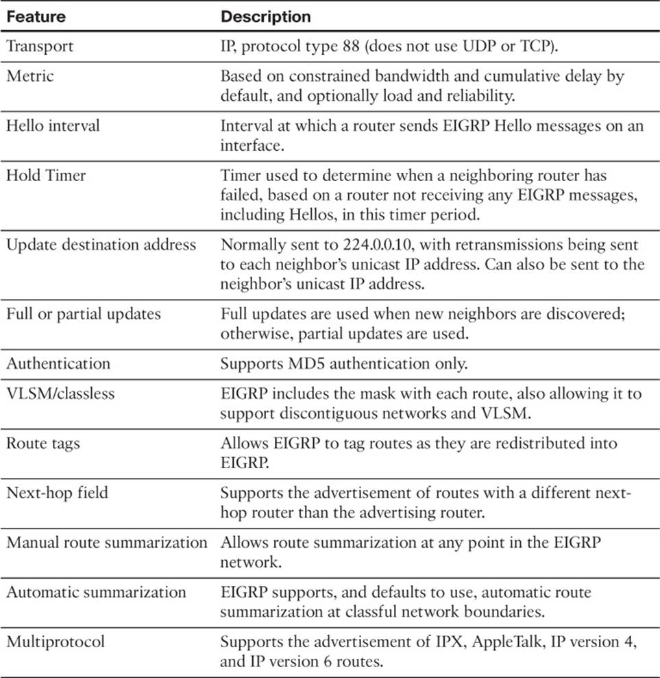
Table 4-3 summarizes some of the key facts about EIGRP.
Table 4-3EIGRP Feature Summary
This completes the CCNA-level EIGRP review. The rest of this chapter now examines EIGRP neighbor relationships.
EIGRP Neighborships
Like OSPF, EIGRP uses three major steps to achieve its goal of learning the best available loop-free routes:
Step 1. Establish EIGRP neighbor relationships—neighborships—with other routers that share a common subnet.
Step 2. Exchange EIGRP topology data with those neighbors.
Step 3. Calculate the currently best IP route for each subnet, based on the known EIGRP topology data, and add those best routes to the IP routing table.
This three-step process hinges on the first step—the successful creation of neighbor relationships between EIGRP routers. The basic EIGRP configuration described earlier in this chapter, particularly the network command, most directly tells EIGRP on which interfaces to dynamically discover neighbors. After EIGRP neighborships have been formed with neighboring routers that are reachable through those interfaces, the final two steps occur without any additional direct configuration.
EIGRP dynamically discovers neighbors by sending EIGRP Hello messages on each EIGRP-enabled interface. When two routers hear EIGRP Hello messages from each other, they check the EIGRP parameters listed in those messages and decide whether the two routers should or should not become neighbors.
The rest of this section focuses on topics related to EIGRP neighborship, specifically:
Manipulating EIGRP Hello and Hold Timers
Controlling whether routers become neighbors by using either passive interfaces or statically defined neighbors
Examining configuration settings that can prevent EIGRP neighborships
Manipulating EIGRP Hello and Hold Timers
The word convergence defines the overall process by which routers notice internetwork topology changes, communicate about those changes, and change their routing tables to contain only the best currently working routes. EIGRP converges very quickly, even with all default settings.
One of the slower components of the EIGRP convergence process relates to the timers that EIGRP neighbors use to recognize that a neighborship has failed. If the interface over which the neighbor is reachable fails, and Cisco IOS changes the interface state to anything other than “up/up,” a router immediately knows that the neighborship should fail. However, in some cases, an interface state might stay “up/up” during times when the link is not usable. In such cases, EIGRP convergence relies on the Hold Timer to expire, which by default, on LANs, means a 15-second wait. (The default EIGRP Hold time on interfaces/subinterfaces with a bandwidth of T1 or lower, with an encapsulation type of Frame Relay, is 180 seconds.)
The basic operation of these two timers is relatively simple. EIGRP uses the Hello messages in part as a confirmation that the link between the neighbors still works. If a router does not receive a Hello from a neighbor for one entire Hold time, that router considers the neighbor to be unavailable. For example, with a default LAN setting of Hello = 5 and Hold = 15, the local router sends Hellos every 5 seconds. The neighbor resets its downward-counting Hold Timer to 15 upon receiving a Hello from that neighbor. Under normal operation on a LAN, with defaults, the Hold Timer for a neighbor would vary from 15, down to 10, and then be reset to 15. However, if the Hellos were no longer received for 15 seconds, the neighborship would fail, driving convergence.
To optimize convergence, an engineer could simply reduce the Hello and Hold Timers, accepting insignificant additional overhead, in return for shorter convergence times. These settings can be made per interface/subinterface, and per EIGRP process.
Note
Although expected to be outside the scope of CCNP, EIGRP can also use the Bi-directional Forwarding Detection (BFD) feature, which provides a means for subsecond detection of a failure in IP connectivity between two neighboring routers.
Configuring the Hello/Hold Timers
Most design engineers would normally choose Hello/Hold Timers that match on all router interfaces on a subnet. However, these settings do not have to match. Interestingly, by setting the Hello and Hold Timers to nondefault values, you can see some oddities with how EIGRP neighbors use these values.
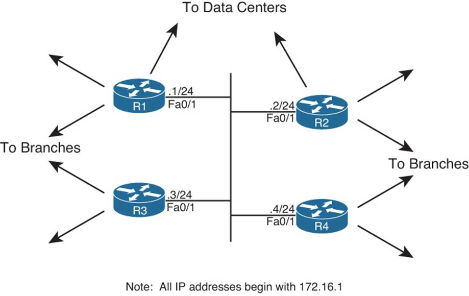
For example, consider four WAN distribution routers, as shown in Figure 4-3. These routers might each have a number of Frame Relay PVCs to remote branches, or multiple MPLS VPN connections to branches. However, to communicate with each other and with data centers at the home office, these four routers connect through a core VLAN/subnet. Note that the design shows routers, rather than Layer 3 switches, but the concept is the same in either case.
Figure 4-3Four WAN Distribution Routers on the Same VLAN/Subnet
A design that hoped to speed EIGRP convergence might call for setting the Hello and Hold Timers to 2 and 6, respectively. (The Hold Timer does not have to be three times the Hello Timer, but the 3:1 ratio is a reasonable guideline.) However, to make an important point about operation of the configuration commands, Example 4-3 sets only R1’s Fa0/1 timers to the new values. Note that in this case, EIGRP has already been configured on all four routers, using ASN 9.
Example 4-3EIGRP Hello and Hold Timer Configuration—R1
interface Fastethernet0/1 ip hello-interval eigrp 9 2 ip hold-time eigrp 9 6
A couple of interesting points can be made about the operation of these seemingly simple commands. First, these two settings can be made per interface/subinterface, but not per neighbor. In Figure 4-3, the Example 4-3 configuration then applies on R1 for all three neighbors reachable on interface Fa0/1.
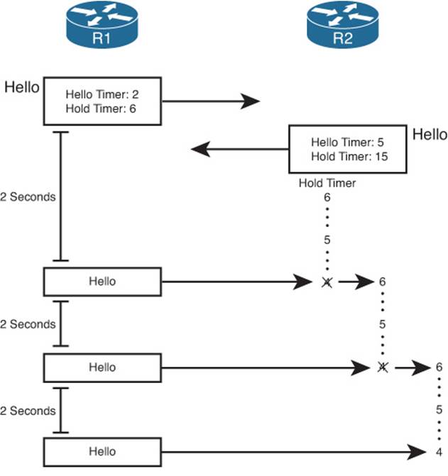
The second interesting point about these commands is that one parameter (the Hello Interval) tells R1 what to do, whereas the other (the Hold Timer) actually tells the neighboring routers what to do. As shown in Figure 4-4, the ip hello-interval eigrp 9 2 interface subcommand tells R1 to send Hellos every 2 seconds. However, the ip hold-time eigrp 9 6 interface subcommand tells R1, again for the EIGRP process with ASN 9, to tell its neighbors to use a Hold Timer of 6 for their respective neighbor relationships with R1. In short, the EIGRP Hello message sent by R1 announces the Hold Timer that other routers should use in the neighbor relationship with R1. Figure 4-4 shows this idea in graphical form.
Figure 4-4R1 Announcing New Hello and Hold Timers
Note
Cisco IOS does not prevent you from making the unfortunate configuration choice of setting the Hold Timer to a value smaller than the Hello interval. In such a case, the neighborship repeatedly fails and recovers, flapping routes in and out of the routing table.
Verifying the Hello/Hold Timers
To find the Hello interface and Hold time configured on a router’s interface, you could of course look at a router’s configuration, but the show running-config command might not be available to you on some question types on the ROUTE exam. However, if you have access to only user mode, you can issue the show ip eigrp interfaces detailtype number command. It’s important to note, however, that if you use that command on some older versions of Cisco IOS, the Hold time might not displayed.
Example 4-4 shows some sample command output from R1, R2, and R3. Note that the Hello and Hold Timer settings on R1 are all in the range of 10–15 seconds, because the timers on R2, R3, and R4 all still default to 5 and 15 seconds, respectively. R2’s neighborship with R1 lists a Hold Timer of 4, which is within the expected range of 4–6 seconds remaining.
Example 4-4Demonstration that R2 and R3 Use R1’s Configured Hold Timer
! On Router R1:
Preventing Unwanted Neighbors Using Passive Interfaces
When an EIGRP network configuration subcommand matches an interface, EIGRP on that router does two things:
Step 1. Attempts to find potential EIGRP neighbors by sending Hellos to the 224.0.0.10 multicast address
Step 2. Advertises the subnet connected to that interface
In some cases, however, no legitimate EIGRP neighbors might exist off an interface. For example, consider the small internetwork shown in Figure 4-5, with three routers, and with only one router connected to each LAN interface. Each router needs to advertise the subnets connected to their various FastEthernet interfaces, but at the same time, there is no benefit to multicast EIGRP Hellos on those interfaces, because only one router connects to each LAN.
Figure 4-5LAN Interfaces That Benefit from the Passive Interface Feature
The network designer can reasonably choose to limit EIGRP on those interfaces that have no legitimate EIGRP neighbors. However, the subnets connected to those same interfaces also typically need to be advertised by EIGRP. For example, subnet 10.1.1.0/24, off R1’s Fa0/0 interface, still needs to be advertised by EIGRP, even though R1 should never find an EIGRP neighbor on that interface.
Given such a requirement—to advertise the subnet while disallowing EIGRP neighborships on the interface—an engineer has two main configuration options to choose from:
Enable EIGRP on the interface using the EIGRP network command, but tell the router to not send any EIGRP messages on the interface by making the interface passive (using the passive-interface command).
Do not enable EIGRP on the interface, and advertise the connected route using route redistribution (and the redistribute connected configuration command).
The first option relies on the passive interface feature—a feature specifically created with this design requirement in mind. When an interface is passive, EIGRP does not send any EIGRP messages on the interface—multicasts or EIGRP unicasts—and the router ignores any EIGRP messages received on the interface. However, EIGRP still advertises the connected subnets if matched with an EIGRP network command. As a result, the first option in the preceding list directly meets all the design requirements. It has the added advantage of being very secure in that no EIGRP neighborships are possible on the interface.
The second option—redistributing connected subnets—also works, but frankly it is the less preferred option in this case. Specifically, the passive interface option clearly meets the design requirements, while the redistribution option causes the connected route to be advertised as an external EIGRP route. This could cause problems in some cases with multiple redistribution points between routing domains (as discussed in Chapter 10, “Route Redistribution”).
The configuration of the passive interface itself is fairly straightforward. To configure the passive interface option, these three routers could be configured as shown in Example 4-5.
Example 4-5Configuration ofpassive-interfaceCommands on R1, R2, and R3
! On Router R1:
! On Router R2:
! On Router R3:
R1’s configuration lists two passive-interface commands, one per LAN interface. As a result, R1 no longer sends EIGRP messages on these two interfaces, including the multicast EIGRP Hellos used to discover neighbors.
R2’s configuration uses a slightly different option: the passive-interface default command. This command essentially changes the default for an interface from not being passive to instead being passive. Then, to make an interface not passive, you have to use a no version of the passive-interface command for those interfaces.
Two commands help to verify that the passive interface design is working properly. First, the show ip eigrp interfaces command omits passive interfaces, listing the nonpassive interfaces matched by a network command. Alternatively, the show ip protocols command explicitly lists all passive interfaces. Example 4-6 shows samples of both commands on R2.
Example 4-6Verifying the Results ofpassive-interfaceon R2
R2# show ip eigrp interfaces IP-EIGRP interfaces for process 1
Xmit Queue Mean Pacing Time Multicast Pending Interface Peers Un/Reliable SRTT Un/Reliable Flow Timer Routes Se0/0/0 1 0/0 32 0/15 159 0 Se0/0/1 1 0/0 1290 0/15 6443 0 R2# show ip protocols Routing Protocol is "eigrp 1" Outgoing update filter list for all interfaces is not set Incoming update filter list for all interfaces is not set Default networks flagged in outgoing updates Default networks accepted from incoming updates EIGRP metric weight K1=1, K2=0, K3=1, K4=0, K5=0 EIGRP maximum hopcount 100 EIGRP maximum metric variance 1 Redistributing: eigrp 1 EIGRP NSF-aware route hold timer is 240s Automatic network summarization is in effect Maximum path: 4 Routing for Networks: 10.0.0.0 Passive Interface(s): FastEthernet0/0 FastEthernet0/1 Routing Information Sources: Gateway Distance Last Update 10.1.12.1 90 00:00:39 10.1.23.1 90 00:00:39 Distance: internal 90 external 170
Controlling Neighborships with Static Configuration
EIGRP supports the ability to statically define neighbors instead of dynamically discovering neighbors.
Although seldom used, you can use this feature to reduce the overhead associated with EIGRP multicast messages. Frame Relay WANs in particular might benefit from the static neighbor definitions, because to support multicasts and broadcasts over Frame Relay, a router must replicate a frame and send a copy over every PVC associated with the interface or subinterface. For example, if a multipoint subinterface has ten PVCs associated with it, but only two of the remote routers used EIGRP, without static neighbors, all ten routers would be sent a copy of the EIGRP multicast Hello packets. With static neighbor definitions for the two routers, EIGRP messages would be sent as unicasts to each of the two neighbors, with no EIGRP messages sent to the eight non-EIGRP routers, reducing overhead.
The configuration seems simple, but it has a few subtle caveats. This section examines the straightforward configuration first and then examines the caveats.
Configuring Static EIGRP Neighbors
To define a neighbor, both routers must configure the neighborip-address outgoing-interface EIGRP router subcommand. The IP address is the interface IP address of the neighboring router. Also, the configured IP address must be from the subnet connected to the interface listed in theneighbor command; otherwise, the command is rejected. Also, note that the EIGRP configuration still needs a network command that matches the interface referenced by the neighbor command.
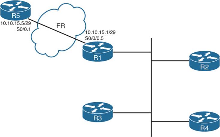
For example, consider Figure 4-6, which adds a new router (R5) to the internetwork of Figure 4-3. R1 and R5 have a PVC connecting them, with IP addresses and subinterface numbers shown.
Figure 4-6Adding a Branch, with a Static EIGRP Neighbor
Example 4-7 shows the configuration on both R1 and R5 to use static neighbor definitions. Of note, R1’s neighbor command refers to R5’s IP address on their common subnet (10.10.15.5), with R1’s local interface (S0/0/0.5). R5 lists the reverse, with R1’s 10.10.15.1 IP address and R5’s local S0/0.1 interface. Also note that both routers have a network command that references network 10.0.0.0, and both routers do advertise subnet 10.10.15.0/29.
The show ip eigrp neighbors command does not identify a neighbor as static, but the show ip eigrp neighbors detail command does. Example 4-7 shows the more detailed output near the end, with the designation of 10.10.15.5 (R5) as a static neighbor.
Example 4-7Static EIGRP Neighborship Between R1 and R5
! New configuration on router R1 R1# show running-config ! lines omitted router eigrp 9 network 172.16.0.0 network 10.0.0.0 no auto-summary neighbor 10.10.15.5 Serial0/0/0.5 ! Back to R1 R1# show ip eigrp neighbors detail IP-EIGRP neighbors for process 9 H Address Interface Hold Uptime SRTT RTO Q Seq (sec) (ms) Cnt Num 3 10.10.15.5 Se0/0/0.5 10 00:00:51 15 200 0 2 Static neighbor Version 12.4/1.2, Retrans: 0, Retries: 0 2 172.16.1.2 Fa0/1 11 00:02:57 3 200 0 25 Version 12.4/1.2, Retrans: 1, Retries: 0 1 172.16.1.3 Fa0/1 10 00:03:45 5 200 0 21 Version 12.4/1.2, Retrans: 0, Retries: 0 0 172.16.1.4 Fa0/1 13 00:03:45 5 200 0 18
! R5's new config added to support the neighbor R5# show running-config ! lines omitted router eigrp 9 network 10.0.0.0 no auto-summary neighbor 10.10.15.1 Serial0/0.1
Caveat When Using EIGRP Static Neighbors
Cisco IOS changes how it processes EIGRP packets on any interface referenced by an EIGRP neighbor command. Keeping in mind the design goal for this feature—to reduce multicasts—Cisco IOS disables all EIGRP multicast packet processing on an interface when an EIGRP neighborcommand has been configured. For example, in Example 4-7, R1’s S0/0/0.5 subinterface will not process EIGRP multicast packets any more as a result of R1’s neighbor 10.10.15.5 Serial0/0/0.5 EIGRP subcommand.
Because of the operation of the EIGRP neighbor command, if at least one EIGRP static neighbor is defined on an interface, no dynamic neighbors can be either discovered or continue to work if already discovered. For example, again in Figure 4-6 and Example 4-7, if R1 added a neighbor 172.16.1.5 FastEthernet0/1 EIGRP subcommand, R1 would lose its current neighborships with Routers R2, R3, and R4.
Configuration Settings That Could Prevent Neighbor Relationships
Some of the configuration settings already mentioned in this chapter, when configured incorrectly, might prevent EIGRP neighborships. This section summarizes those settings, and introduces a few other configuration settings that can prevent neighbor relationships. The list of items that must match—and that do not have to match—can be a useful place to start troubleshooting neighbor initialization problems in real life, and to troubleshoot neighborship problems for simulation questions on the CCNP ROUTE exam.
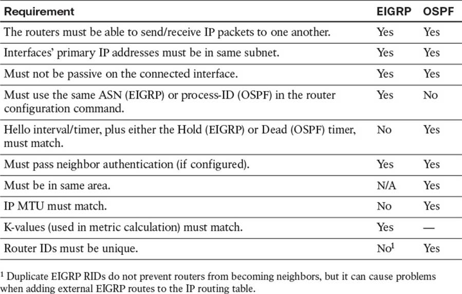
Table 4-4 lists the neighbor requirements for both EIGRP and Open Shortest Path First (OSPF). (OSPF is included here just as a frame of reference for those more familiar with OSPF; this information will be repeated in Chapter 7, “Fundamental OSPF Concepts,” which discusses OSPF neighborship requirements.) Following the table, the next few pages examine some of these settings for EIGRP.
Table 4-4Neighbor Requirements for EIGRP and OSPF
Going through Table 4-4 sequentially, the first two items relate to IP connectivity. Two routers must be able to send and receive IP packets with each other. Additionally, the primary IP address on the interfaces—in other words, the IP address configured without the secondary keyword on theip address command—must be in the same subnet.
Note
It should not matter for CCNP ROUTE, but possibly for CCIE R/S: EIGRP’s rules about neighbor IP addresses being in the same subnet are less exact than OSPF. OSPF requires matching subnet numbers and masks. EIGRP just asks the question of whether the neighbor’s IP address is in the range of addresses for the subnet as known to the local router. For example, two routers with addresses of 10.1.1.1/24 (range 10.1.1.1–10.1.1.254) and 10.1.1.2/30 (range 10.1.1.1–10.1.1.2) would actually allow EIGRP neighborship, because each router believes the neighbor’s IP address to be in the same subnet as the local router.
The next three items in Table 4-4—passive interfaces, matching the EIGRP ASN number, and allowing mismatching Hello/Hold Timers—have already been covered in this chapter.
The next item, authentication, is discussed in detail in Chapter 17, “Routing Protocol Authentication.”
The next two items in the table—matching the IP MTU and matching OSPF areas—do not prevent EIGRP neighborships. These topics, are requirements for OSPF neighborship and will be discussed in Chapter 7.
Finally, the last two items in the table (K-values and router IDs) each require more than a cursory discussion for EIGRP and will be explained in the upcoming pages.
Configuring EIGRP Metric Components (K-values)
EIGRP calculates its integer metric, by default, using a formula that uses constraining bandwidth and cumulative delay. You can change the formula to use link reliability and link load, and even disable the use of bandwidth and/or delay. To change the formula, an engineer can configure five weighting constants, called K-values, which are represented in the metric calculation formula as constants K1, K2, K3, K4, and K5.
From a design perspective, Cisco strongly recommends against using link load and link reliability in the EIGRP metric calculation. Most shops that use EIGRP never touch the K-values at all. However, in labs, it can be useful to disable the use of bandwidth from the metric calculation, because that simplifies the metric math and makes it easier to learn the concepts behind EIGRP.
The metric weights command sets five variables (K1 through K5), each of which weights the metric calculation formula more or less heavily for various parts of the formula. Mismatched K-value settings prevent two routers from becoming neighbors. Thankfully, determining whether such a mismatch exists is easy. When a router receives an EIGRP Hello with mismatched K-values (as compared to itself), the router issues a log message stating that a K-value mismatch exists. You can also examine the values either by looking at the running configurations or by looking for the K-values listed in the output of the show ip protocols command, as shown in Example 4-8.
Note
In the command metric weights 0 1 0 1 1 0, the first number (that is, the leftmost 0) represents the Type of Service (ToS) value with which EIGRP packets should be marked. This is a Quality of Service (QoS) setting. It equals 0 and cannot be changed to a different value. The remaining five numbers are the K-values: K1, K2, K3, K4, and K5, respectively.
Example 4-8Mismatched K-values
R2(config)# router eigrp 1 R2(config-router)# metric weights 0 1 0 1 1 0 R2(config-router)# end Feb 23 18:48:21.599: %DUAL-5-NBRCHANGE: IP-EIGRP(0) 1: Neighbor 10.1.12.1 (Serial0/0/1) is down: metric changed R2# Feb 23 18:48:24.907: %DUAL-5-NBRCHANGE: IP-EIGRP(0) 1: Neighbor 10.1.12.1 (Serial0/0/1) is down: K-value mismatch R2# show ip protocols Routing Protocol is "eigrp 1" Outgoing update filter list for all interfaces is not set Incoming update filter list for all interfaces is not set Default networks flagged in outgoing updates Default networks accepted from incoming updates EIGRP metric weight K1=1, K2=0, K3=1, K4=1, K5=0 ! lines omitted for brevity
EIGRP Router ID
EIGRP uses a concept of a representing each router with a router ID (RID). The EIGRP RID is a 32-bit number, represented in dotted decimal. Each router determines its RID when the EIGRP process starts, using the same general rules as does OSPF for determining the OSPF RID, as follows:
Step 1. Use the configured value (using the eigrp router-ida.b.c.d EIGRP subcommand).
Step 2. Use the highest IPv4 address on an up/up loopback interface.
Step 3. Use the highest IPv4 address on an up/up nonloopback interface.
Although EIGRP does require each router to have an RID, the actual value is of little practical importance. The EIGRP show commands seldom list the RID value, and unlike OSPF RIDs, engineers do not need to know each router’s EIGRP RID to interpret the EIGRP topology database. Additionally, although it is best to make EIGRP RIDs unique, duplicate RIDs do not prevent routers from becoming neighbors.
The only time the value of EIGRP RIDs matters is when injecting external routes into EIGRP. In that case, the routers injecting the external routes must have unique RIDs to avoid confusion.
Neighborship over WANs
EIGRP configuration and neighborship rules do not differ when comparing typical LAN and typical WAN technologies. However, some design and operational differences exist, particularly regarding which routers become neighbors with which other routers. This short section closes the EIGRP neighbor discussion with a brief look at Frame Relay, MPLS VPNs, and Metro Ethernet as implemented with Virtual Private LAN Service (VPLS).
Neighborship on Frame Relay
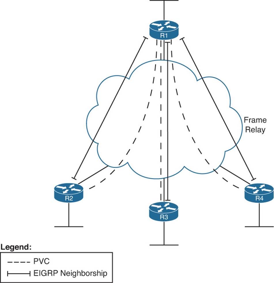
Frame Relay provides a Layer 2 WAN service. Each router connects to the service using a physical serial link, called a Frame Relay access link. The provider then creates logical connections, called permanent virtual circuits (PVC), which are logical paths between pairs of routers connected to a Frame Relay service. Any pair of routers that connect to the ends of a Frame Relay PVC can send Frame Relay frames to each other. Therefore, they can send IP packets and become EIGRP neighbors. Figure 4-7 shows a typical case, with R1 as a central-site router, and R2, R3, and R4 acting as branch routers.
Figure 4-7EIGRP Neighborships over Frame Relay
Figure 4-7 shows EIGRP neighborships, but note that all routers can learn all routes in the internetwork, even though not all routers become neighbors. The neighborships can only form when a PVC exists between the two routers.
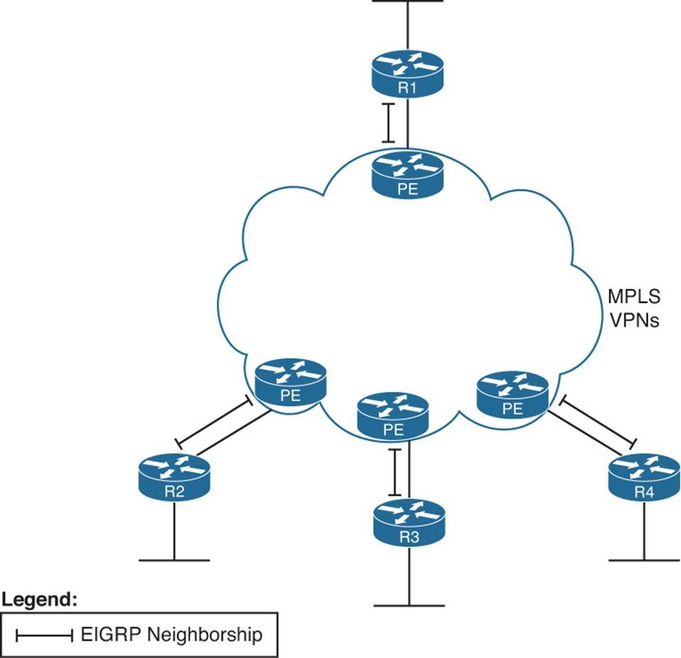
Neighborship on MPLS VPN
Multiprotocol Label Switching (MPLS) Virtual Private Networks (VPN) create a WAN service that has some similarities but many differences when compared to Frame Relay. The customer routers connect to the service, often with serial links but at other times with Frame Relay PVCs or with Ethernet. The service itself is a Layer 3 service, forwarding IP packets through a cloud. As a result, no predefined PVCs need to exist between the customer routers. Additionally, the service uses routers at the edge of the service provider cloud—generically called provider edge (PE)routers—and these routers are Layer 3 aware.
That Layer 3 awareness means that the customer edge (CE) routers form an EIGRP neighborship with the PE router on the other end of their local access link, as shown in Figure 4-8. The PE routers exchange their routes, typically using Multiprotocol BGP (MP-BGP), a topic outside the scope of this book. However, all the CE routers then learn routes from each other, although each CE router has only one EIGRP neighborship for each of its connections into the MPLS VPN cloud.
Figure 4-8EIGRP Neighborships over MPLS VPN
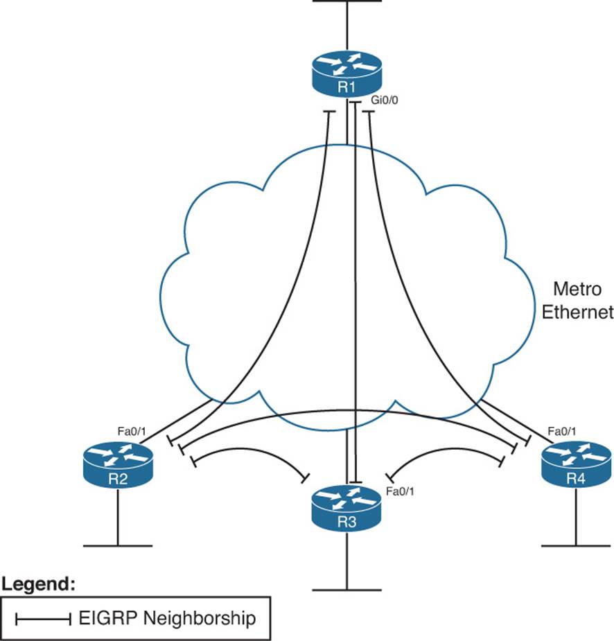
Neighborship on Metro Ethernet
The term Metropolitan Ethernet (MetroE) represents a range of Layer 2 WAN services in which the CE device connects to the WAN service using some form of Ethernet. Because MetroE provides a Layer 2 Ethernet service, the service delivers an Ethernet frame sent by one customer router to another customer router (for unicast frames), or to many other routers (for multicast or broadcast frames).
MetroE encompasses several underlying technologies to create the service. Of note for the purposes of this book are the Virtual Private Wire Service (VPWS) and the Virtual Private LAN Service (VPLS). Both technical specifications allow for connections using Ethernet links, with the service forwarding Ethernet frames. VPWS focuses on point-to-point topologies, whereas VPLS supports multipoint, approximating the concept of the entire WAN service acting like one large Ethernet switch. Because it is a Layer 2 service, MetroE does not have any Layer 3 awareness, and customer routers (typically referenced with the more general service provider term customer premises equipment, or CPE) see the MetroE service as a VLAN. Because the customer routers connect to the service as a VLAN, all the routers connected to the service can become EIGRP neighbors, as shown in Figure 4-9.
Figure 4-9EIGRP Neighborships over Metro Ethernet
Exam Preparation Tasks
Planning Practice
The CCNP ROUTE exam expects test takers to be able to review design documents, create implementation plans, and create verification plans. This section provides some exercises that can help you to take a step back from the minute details of the topics in this chapter, so that you can think about the same technical topics from the planning perspective.
For each planning practice table, simply complete the table. Note that any numbers in parentheses represent the number of options listed for each item in the solutions in Appendix F, “Completed Planning Practice Tables,” which you can find on the CD-ROM accompanying this book.
Design Review Table
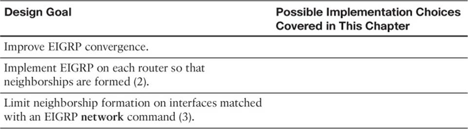
Table 4-5 lists several design goals related to this chapter. If these design goals were listed in a design document, and you had to take that document and develop an implementation plan, what implementation options come to mind? For any configuration items, a general description can be used, without any concern about the specific parameters.
Table 4-5Design Review
Implementation Plan Peer Review Table
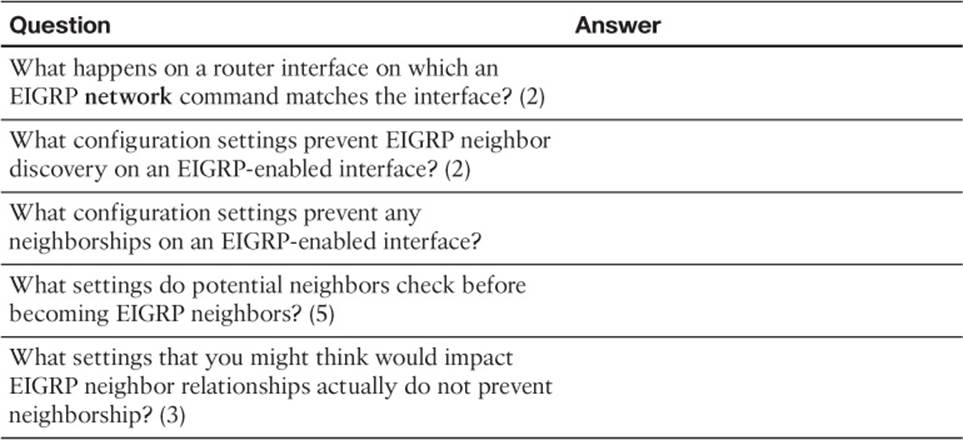
Table 4-6 shows a list of questions that others might ask, or that you might think about, during a peer review of another network engineer’s implementation plan. Complete the table by answering the questions.
Table 4-6Notable Questions from This Chapter to Consider During an Implementation Plan Peer Review
Create an Implementation Plan Table
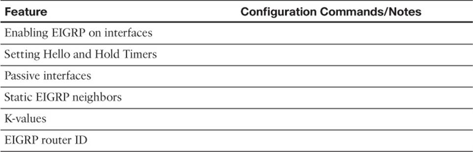
To practice skills useful when creating your own EIGRP implementation plan, list in Table 4-7 configuration commands related to the configuration of the following features. You might want to record your answers outside the book, and set a goal to complete this table (and others like it) from memory during your final reviews before taking the exam.
Table 4-7Implementation Plan Configuration Memory Drill
Choose Commands for a Verification Plan Table
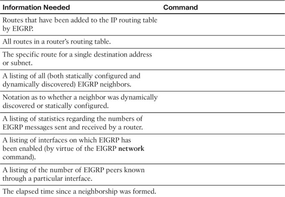
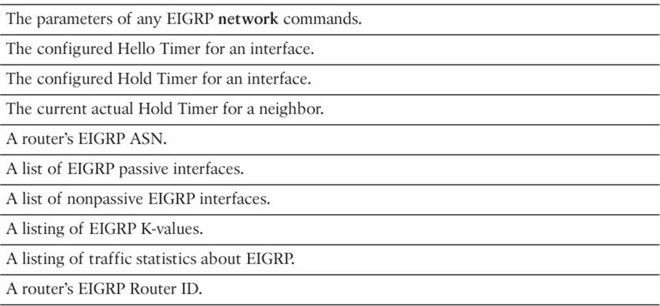
To practice skills useful when creating your own EIGRP verification plan, list in Table 4-8 all commands that supply the requested information. You might want to record your answers outside the book, and set a goal to complete this table (and others like it) from memory during your final reviews before taking the exam.
Table 4-8Verification Plan Memory Drill
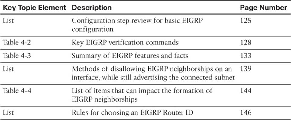
Review All the Key Topics
Review the most important topics from inside the chapter, noted with the Key Topic icon in the outer margin of the page. Table 4-9 lists a reference of these key topics and the page numbers on which each is found.
Table 4-9Key Topics for Chapter 4
Complete the Tables and Lists from Memory
Print a copy of Appendix D, “Memory Tables,” (found on the CD), or at least the section for this chapter, and complete the tables and lists from memory. Appendix E, “Memory Tables Answer Key,” also on the CD, includes completed tables and lists to check your work.
Define Key Terms
Define the following key terms from this chapter, and check your answers in the glossary: