CCNP Routing and Switching TSHOOT 300-135 Official Cert Guide (2015)
Part II. Troubleshooting Cisco Catalyst Switch Features
Chapter 8. Troubleshooting First-Hop Redundancy Protocols
This chapter covers the following topics:
![]() Troubleshooting HSRP: This section focuses on the Cisco Hot Standby Router Protocol (HSRP). It reviews the HSRP features and functions and how you can verify HSRP configurations and troubleshoot HSRP issues.
Troubleshooting HSRP: This section focuses on the Cisco Hot Standby Router Protocol (HSRP). It reviews the HSRP features and functions and how you can verify HSRP configurations and troubleshoot HSRP issues.
![]() HSRP Trouble Tickets: This section provides trouble tickets that demonstrate how you can use a structured troubleshooting process to solve a reported problem.
HSRP Trouble Tickets: This section provides trouble tickets that demonstrate how you can use a structured troubleshooting process to solve a reported problem.
![]() Troubleshooting VRRP: This section focuses on the industry standard Virtual Router Redundancy Protocol (VRRP). It reviews the VRRP features and functions as well as how you can verify VRRP configurations and troubleshoot VRRP issues.
Troubleshooting VRRP: This section focuses on the industry standard Virtual Router Redundancy Protocol (VRRP). It reviews the VRRP features and functions as well as how you can verify VRRP configurations and troubleshoot VRRP issues.
![]() VRRP Trouble Tickets: This section provides trouble tickets that demonstrate how you can use a structured troubleshooting process to solve a reported problem.
VRRP Trouble Tickets: This section provides trouble tickets that demonstrate how you can use a structured troubleshooting process to solve a reported problem.
![]() Troubleshooting GLBP: This section focuses on the Cisco Gateway Load Balancing Protocol (GLBP). It reviews the GLBP features and functions and how you can verify GLBP configurations and troubleshoot GLBP issues.
Troubleshooting GLBP: This section focuses on the Cisco Gateway Load Balancing Protocol (GLBP). It reviews the GLBP features and functions and how you can verify GLBP configurations and troubleshoot GLBP issues.
![]() GLBP Trouble Tickets: This section provides trouble tickets that demonstrate how you can use a structured troubleshooting process to solve a reported problem.
GLBP Trouble Tickets: This section provides trouble tickets that demonstrate how you can use a structured troubleshooting process to solve a reported problem.
![]() Comparing HSRP, VRRP, and GLBP: This section provides a close-up comparison of the different first-hop redundancy protocols (FHRPs) covered in the chapter.
Comparing HSRP, VRRP, and GLBP: This section provides a close-up comparison of the different first-hop redundancy protocols (FHRPs) covered in the chapter.
Many devices, such as PCs, are configured with a default gateway. The default gateway parameter identifies the IP address of a next-hop router on the local-area network (LAN) that serves as the exit point for the LAN. As a result, if that router were to become unavailable, devices that relied on the default gateway’s IP address would be unable to send traffic off their local subnet.
Fortunately, Cisco devices such as routers and Layer 3 switches offer technologies known as first-hop redundancy protocols (FHRPs) that provide next-hop gateway redundancy. These technologies include HSRP, VRRP, and GLBP, which allow clients to continue to reach their default gateway’s IP address, even if the Layer 3 switch or router that had been servicing that IP address becomes unavailable.
This chapter reviews HSRP, VRRP, and GLBP, and provides a collection of Cisco IOS commands you can use to troubleshoot issues related to them.
“Do I Know This Already?” Quiz
The “Do I Know This Already?” quiz allows you to assess whether you should read this entire chapter thoroughly or jump to the “Exam Preparation Tasks” section. If you are in doubt about your answers to these questions or your own assessment of your knowledge of the topics, read the entire chapter. Table 8-1 lists the major headings in this chapter and their corresponding “Do I Know This Already?” quiz questions. You can find the answers in Appendix A, “Answers to the ‘Do I Know This Already?’ Quizzes.”
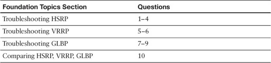
Table 8-1 “Do I Know This Already?” Section-to-Question Mapping
Caution
The goal of self-assessment is to gauge your mastery of the topics in this chapter. If you do not know the answer to a question or are only partially sure of the answer, you should mark that question as wrong for purposes of the self-assessment. Giving yourself credit for an answer that you correctly guess skews your self-assessment results and might provide you with a false sense of security.
1. What is the default priority for an HSRP interface?
a. 0
b. 100
c. 256
d. 32768
2. How many active forwarders can be in an HSRP group?
a. 1
b. 2
c. 4
d. No limit
3. What command enables you to verify the virtual MAC address of an HSRP group?
a. show hsrp
b. show hsrp brief
c. show standby
d. show standby brief
4. Which two of the following are true about HSRP?
a. Preemption is on by default.
b. Preemption is off by default.
c. The virtual router IP address can be an unused IP in the LAN or an IP associated with a router’s LAN interface.
d. The virtual router IP address has to be an unused IP in the LAN.
5. What is the name for the router in a VRRP virtual router group that is actively forwarding traffic on behalf of the virtual router group?
a. Virtual forwarder
b. Active virtual gateway
c. Virtual router master
d. Active virtual forwarder
6. Which two of the following are true about VRRP? (Choose two answers.)
a. Preemption is on by default.
b. Preemption is off by default.
c. The virtual router IP address can be an unused IP in the LAN or an IP associated with a router’s LAN interface.
d. The virtual router IP address has to be an unused IP in the LAN.
7. Which show commands enable you to verify the virtual MAC addresses that an AVF is responsible for? (Choose two answers.)
a. show run
b. show arp
c. show glbp
d. show glbp brief
8. Which of the following is the default GLBP method for load balancing?
a. Weighted
b. Host dependent
c. Server dependent
d. Round-robin
9. Which of the following statements is true concerning GLBP?
a. GLBP is an industry-standard FHRP.
b. GLBP allows multiple routers to simultaneously forward traffic.
c. The active virtual forwarder in a GLBP group is responsible for responding to ARP requests with different MAC addresses.
d. A GLBP group has multiple active virtual gateways.
10. Which of the following are Cisco proprietary FHRPs? (Choose two answers.)
a. HSRP
b. VRRP
c. GLBP
d. IRDP
Foundation Topics
Troubleshooting HSRP
Hot Standby Router Protocol (HSRP) is a Cisco Proprietary FHRP that was designed to provide default gateway redundancy. HSRP operates on both Cisco routers and Cisco multilayer switches. When implemented, it allows multiple physical layer 3 gateways to appear as a single virtual layer 3 gateway. It is this virtual layer 3 gateway that the clients point to as their default gateway.
As a troubleshooter you will need to have a very solid understanding of how HSRP functions in order to resolve any issues related to HSRP. In this section you will review the concepts of HSRP as well as how to verify and troubleshoot HSRP configurations.
Reviewing HSRP
HSRP uses a virtual IP address and MAC address to represent a virtual router within an HSRP group. The end-stations’ default gateway IP address is the IP address of the virtual router. When the end-stations ARP for the MAC address of the default gateway IP address, they are given thevirtual MAC address. Under no circumstances should the end-stations ever be given the real MAC address of the device that is acting as the default gateway when they are ARPing for the MAC of the virtual IP address.
Within an HSRP group, one router is the active router. This router is responsible for forwarding data sent to the MAC address of the default gateway and responding to ARP requests asking for the MAC associated with the IP address of the default gateway. Another router in the HSRP group is known as the standby router. This router is waiting for the active router to fail or experience a link/reachability failure so that it can take over the active router role and forward traffic and respond to ARP requests. You can have additional routers in an HSRP group, but they will not be active or standby. They will simply sit and wait for the active or standby to fail so they can elect a replacement among them. Figure 8-1 illustrates a basic HSRP topology.
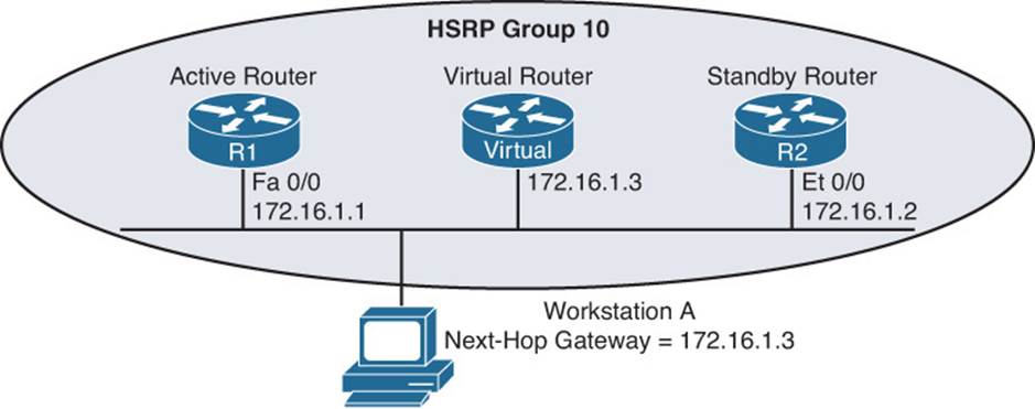
Figure 8-1 Basic HSRP Operation
Examples 8-1 and 8-2 show the HSRP configuration for routers R1 and R2.
Example 8-1 HSRP Configuration on Router R1
R1#show run
...OUTPUT OMITTED...
interface FastEthernet0/0
ip address 172.16.1.1 255.255.255.0
standby 10 ip 172.16.1.3
standby 10 priority 150
standby 10 preempt
...OUTPUT OMITTED...
Example 8-2 HSRP Configuration on Router R2
R2#show run
...OUTPUT OMITTED...
interface Ethernet0/0
ip address 172.16.1.2 255.255.255.0
standby 10 ip 172.16.1.3
...OUTPUT OMITTED...

Notice that both routers R1 and R2 have been configured with the same virtual IP address of 172.16.1.3 for an HSRP group of 10. Router R1 is configured with a higher priority using the standby 10 priority 150 command. Router R2 has a default HSRP priority of 100 for group 10, and with HSRP, higher priority values are more preferable. Also, notice that router R1 is configured with the standby 10 preempt command, which means that if router R1 loses its active status, perhaps because it is powered off, it will regain its active status when it again becomes available.
HSRP Converging After a Failure
By default, HSRP sends hello messages every three seconds. Also, if the standby router does not hear a hello message within ten seconds by default, the standby router considers the active router to be down. The standby router then assumes the active role.
Although this ten-second convergence time applies for a router becoming unavailable for a reason such as a power outage or a link failure, convergence happens more rapidly if an interface is administratively shut down. Specifically, an active router sends a resign message if its active HSRP interface is shut down.
Also, consider the addition of another router to the network segment whose HSRP priority for group 10 is higher than 150. If it were configured for preemption, the newly added router would send a coup message, to inform the active router that the newly added router was going to take on the active role. If, however, the newly added router were not configured for preemption, the currently active router would remain the active router.
HSRP Verification and Troubleshooting
When verifying an HSRP configuration or troubleshooting an HSRP issue, you should begin by determining the following information about the HSRP group under inspection:
![]() Which router is the active router?
Which router is the active router?
![]() Which routers, if any, are configured with the preempt option?
Which routers, if any, are configured with the preempt option?
![]() What is the virtual IP address?
What is the virtual IP address?
![]() What is the virtual MAC address?
What is the virtual MAC address?
![]() Is interface or object tracking on?
Is interface or object tracking on?
The show standby brief command can be used to show which interface is participating in an HSRP group. It identifies the HSRP group number, the priority of the interface, and if preemption is enabled or not. Additionally, this command identifies the router that is currently the active router, the router that is currently the standby router, and the virtual IP address for the HSRP group. Examples 8-3 and 8-4 show the output from the show standby brief command issued on routers R1 and R2, where router R1 is currently the active router for group 10 with a virtual IP of 172.16.1.3. It also has a priority of 150 with preemption enabled. In this case, the router with the IP address 172.16.1.2 is the standby router, which happens to be R2, as shown in Example 8-4.
Example 8-3 show standby brief Command Output on Router R1
R1#show standby brief
P indicates configured to preempt.
|
Interface Grp Prio P State Active Standby Virtual IP
Fa0/0 10 150 P Active local 172.16.1.2 172.16.1.3
Example 8-4 show standby brief Command Output on Router R2
R2#show standby brief
P indicates configured to preempt.
|
Interface Grp Prio P State Active Standby Virtual IP
Et0/0 10 100 Standby 172.16.1.1 local 172.16.1.3
In addition to an interface’s HSRP group number, the interface’s state, and the HSRP group’s virtual IP address, the show standby interface_type interface_number command also displays the HSRP group’s virtual MAC address, the HSRP timers, the standby routers priority, and if the current local priority is different than the configured local priority. Issuing this command on router R1, as shown in Example 8-5, shows that the virtual MAC address for HSRP group 10 is 0000.0c07.ac0a, the timers are default at 3 and 10, the standby routers priority is 100, and the local routers current priority is the same as the configured priority.
Example 8-5 show standby fastethernet 0/0 Command Output on Router R1
R1#show standby fastethernet 0/0
FastEthernet0/0 - Group 10
State is Active
1 state change, last state change 01:20:00
Virtual IP address is 172.16.1.3
Active virtual MAC address is 0000.0c07.ac0a
Local virtual MAC address is 0000.0c07.ac0a (v1 default)
Hello time 3 sec, hold time 10 sec
Next hello sent in 1.044 secs
Preemption enabled
Active router is local
Standby router is 172.16.1.2, priority 100 (expires in 8.321 sec)
Priority 150 (configured 150)
IP redundancy name is "hsrp-Fa0/0-10" (default)
Virtual Router MAC Address
The default virtual MAC address for an HSRPv1 group, as shown in Figure 8-2, is based on the HSRP group number. Specifically, the virtual MAC address for an HSRP group begins with a vendor code of 0000.0c, followed with a well-known HSRPv1 code of 07.ac. The last two hexadecimal digits are the hexadecimal representation of the HSRP group number. Therefore, you can have up to 256 HSRPv1 groups. For example, an HSRP group of 10 yields a default virtual MAC address of 0000.0c07.ac0a, because 10 in decimal equates to 0a in hexadecimal.
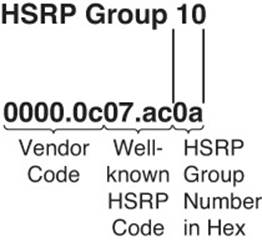
Figure 8-2 HSRP Virtual MAC Address
The default virtual MAC address for an HSRPv2 group begins with a vendor code of 0000.0c, followed with a well-known HSRPv2 code of 9F.F, and then the last three hexadecimal digits represent the HSRPv2 group. Therefore, you can have a total of 4096 HSRPv2 groups.
Interface Tracking
HSRP interface tracking is a feature that most organizations will deploy. By default, HSRP will only detect a failure of the device itself or the path that is used by the hello packets. What about the uplinks from the routers running HSRP? If they fail, hello packets are still exchanged successfully, and the active router is still available. However, if the uplink is down, packets are dropped at the active router because it cannot forward them. This is where interface tracking comes into play. Interface tracking allows you to control the priority of a router in an HSRP group based on the status of an interface. If the interface is anything but up/up, you can decrement the priority of the router to a value that is lower than the standby router, and if preemption is enabled on the standby router, it will take over as the active forwarder because it now has the higher priority. You implement interface tracking with the standby group_number track interface_type interface_number decrement_value command. You can use the show standby command to verify whether interface tracking is configured and the state of the tracked interface, as shown inExample 8-6.
Example 8-6 show standby Command Output on Router R1
R1#show standby fa 0/0
FastEthernet0/0 - Group 10
State is Standby
2 state changes, last state change 00:02:16
Virtual IP address is 172.16.1.3
Active virtual MAC address is 0000.0c07.ac0a
Local virtual MAC address is 0000.0c07.ac0a (v1 default)
Hello time 3 sec, hold time 10 sec
Next hello sent in 0.784 secs
Preemption enabled
Active router is 172.16.1.2, priority 100 (expires in 9.312 sec)
Standby router is local
Priority 99 (configured 110)
Track interface FastEthernet2/0 state Down decrement 11
Group name is "hsrp-Gi0/0-10" (default)
In the case of Example 8-6, you can see that the tracked interface state is down. When it is down, the priority will be decremented by 11. Therefore, reviewing the configured priority of 110 and the current priority of 99 indicates why this router is not the active router at the moment. Its priority has been lowered to 99 from 110 because the interface state is down. Now you would have to troubleshoot why the interface is down, which is beyond the scope of our HSRP discussion.
In addition to interface tracking, you can use object tracking, which allows you to track IP-related information such as a route, a group of objects, the status of a service level agreement (SLA), and the status of an interface. We discuss this type of tracking in the “Troubleshooting VRRP” section.
Verifying First Hop
Once you know the current HSRP configuration, you might then check to see whether a host on the HSRP virtual IP address’s subnet can ping the virtual IP address. Based on the topology previously shown in Figure 8-1, Example 8-7 shows a successful ping from Workstation A.
Example 8-7 Ping Test from Workstation A to the HSRP Virtual IP Address
C:\>ping 172.16.1.3
Pinging 172.16.1.3 with 32 bytes of data:
Reply from 172.16.1.3: bytes=32 time=2ms TTL=255
Reply from 172.16.1.3: bytes=32 time=1ms TTL=255
Reply from 172.16.1.3: bytes=32 time=1ms TTL=255
Reply from 172.16.1.3: bytes=32 time=1ms TTL=255
Ping statistics for 172.16.1.3:
Packets: Sent = 4, Received = 4, Lost = 0 (0% loss),
Approximate round trip times in milli-seconds:
Minimum = 1ms, Maximum = 2ms, Average = 1ms
A client could also be used to verify the appropriate virtual MAC address learned by the client corresponding to the virtual MAC address reported by one of the HSRP routers. Example 8-8 shows Workstation A’s Address Resolution Protocol (ARP) cache entry for the HSRP virtual IP address of 172.16.1.3. Notice in the output that the MAC address learned via ARP does match the HSRP virtual MAC address reported by the active HSRP router.
Example 8-8 Workstation A’s ARP Cache
C:\>arp -a
Interface: 172.16.1.4 --- 0x4
Internet Address Physical Address Type
172.16.1.3 00-00-0c-07-ac-0a dynamic
However, one of the best tools to use with FHRPs to verify the path is traceroute. With traceroute, you can identify the physical first-hop router that the packets are traversing. Example 8-9 displays the tracert command executed on a PC. Notice that it states that the first hop is 172.16.1.1. This is the IP address of R1’s LAN interface. Therefore, we can conclude the R1 is the active forwarder at the moment. However, suppose that a failure happened and R2 became the active forwarder. The ARP cache would still be the same on the PC. However, the output of tracert on the PC would now display that the first hop is 172.16.1.2, as shown in Example 8-10.
Example 8-9 A Trace from Workstation A Confirming That R1 Is the First Hop (Active Forwarder)
C:\>tracert 192.0.2.1
Tracing route to 192.0.2.1 over a maximum of 30 hops
1 7 ms <1 ms 2 ms 172.16.1.1
...output omitted...
Trace complete.
Example 8-10 A Trace from Workstation A Confirming That R2 Is the First Hop (Active Forwarder)
C:\PC1>tracert 192.0.2.1
Tracing route to 192.0.2.1 over a maximum of 30 hops
1 3 ms 2 ms 4 ms 172.16.1.2
...output omitted...
Trace complete.
Debug
You can also use the debug standby terse command to view important HSRP changes, such as a state change. Example 8-11 shows this debug output on router R2 when router R1’s Fast Ethernet 0/0 interface is shut down; notice that router R2’s state changes from standby to active.
Example 8-11 debug standby terse Command Output on Router R2: Changing to Active
R2#
*Mar 1 01:25:45.930: HSRP: Et0/0 Grp 10 Standby: c/Active timer expired
(172.16.1.1)
*Mar 1 01:25:45.930: HSRP: Et0/0 Grp 10 Active router is local, was 172.16.1.1
*Mar 1 01:25:45.930: HSRP: Et0/0 Grp 10 Standby router is unknown, was local
*Mar 1 01:25:45.930: HSRP: Et0/0 Grp 10 Standby -> Active
*Mar 1 01:25:45.930: %HSRP-6-STATECHANGE: Ethernet0/0 Grp 10 state Standby ->
Active
*Mar 1 01:25:45.930: HSRP: Et0/0 Grp 10 Redundancy "hsrp-Et0/0-10" state Standby
-> Active
*Mar 1 01:25:48.935: HSRP: Et0/0 Grp 10 Redundancy group hsrp-Et0/0-10 state
Active -> Active
*Mar 1 01:25:51.936: HSRP: Et0/0 Grp 10 Redundancy group hsrp-Et0/0-10 state
Active -> Active
When router R1’s Fast Ethernet 0/0 interface is administratively enabled, router R1 reassumes its previous role as the active HSRP router for HSRP group 10, because router R1 is configured with the preempt option. The output shown in Example 8-12 demonstrates how router R2 receives a coup message, letting router R2 know that router R1 is taking back its active role.
Example 8-12 debug standby terse Command Output on Router R2: Changing HSRP to Standby
R2#
*Mar 1 01:27:57.979: HSRP: Et0/0 Grp 10 Coup in 172.16.1.1 Active pri 150
vIP 172.16.1.3
*Mar 1 01:27:57.979: HSRP: Et0/0 Grp 10 Active: j/Coup rcvd from higher pri
router (150/172.16.1.1)
*Mar 1 01:27:57.979: HSRP: Et0/0 Grp 10 Active router is 172.16.1.1, was local
*Mar 1 01:27:57.979: HSRP: Et0/0 Grp 10 Active -> Speak
*Mar 1 01:27:57.979: %HSRP-6-STATECHANGE: Ethernet0/0 Grp 10 state Active -> Speak
*Mar 1 01:27:57.979: HSRP: Et0/0 Grp 10 Redundancy "hsrp-Et0/0-10" state Active
-> Speak
*Mar 1 01:28:07.979: HSRP: Et0/0 Grp 10 Speak: d/Standby timer expired (unknown)
*Mar 1 01:28:07.979: HSRP: Et0/0 Grp 10 Standby router is local
*Mar 1 01:28:07.979: HSRP: Et0/0 Grp 10 Speak -> Standby
*Mar 1 01:28:07.979: HSRP: Et0/0 Grp 10 Redundancy "hsrp-Et0/0-10" state Speak
-> Standby
HSRP Trouble Tickets
This section presents various trouble tickets relating to the topics discussed earlier in the chapter. The purpose of these trouble tickets is to give a process that you can follow when troubleshooting in the real world or in an exam environment. All trouble tickets in this section are based on the topology depicted in Figure 8-3.
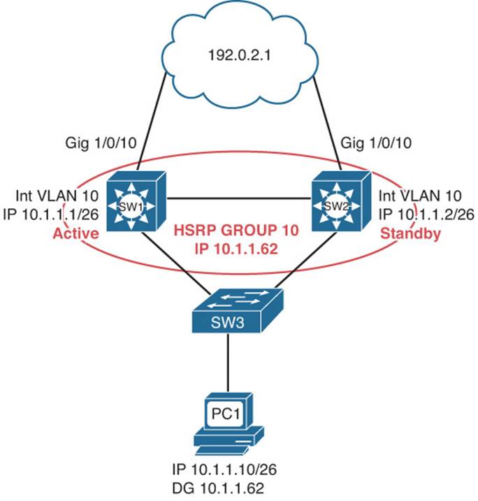
Figure 8-3 HSRP Trouble Ticket Topology
Trouble Ticket 8-1
Problem: According to traffic statistics, all traffic for VLAN 10 is flowing through SW2 to reach the core instead of SW1.
You start by verifying the problem from PC1 on VLAN 10. In this case, the best tool is traceroute because it will identify the router hops (real IPs) along the path. All you care about is the first hop; is it 10.1.1.1 or 10.1.1.2? This will identify whether traffic is flowing though SW1 or SW2 to reach the core. Example 8-13 indicates that SW2 is in fact the HSRP active forwarder for the 10.1.1.0/26 network because it was the first hop returned for the tracert command output.
Example 8-13 A Trace from PC1 Confirming That SW2 Is the First Hop (Active Forwarder)
C:\PC1>tracert 192.0.2.1
Tracing route to 192.0.2.1 over a maximum of 30 hops
1 6 ms 1 ms 2 ms 10.1.1.2
...output omitted
Trace complete.
Next you need to confirm that this is in fact true by reviewing the output of HSRP show commands. Example 8-14 displays the output of show standby brief on SW2. Notice that under the Active column it states local and that under the Standby column it displays 10.1.1.1, which is the IP address of the standby router, SW1.
Example 8-14 show standby brief Command Output on SW2
SW2#show standby brief
P indicates configured to preempt.
|
Interface Grp Pri P State Active Standby Virtual IP
Vl10 10 100 P Active local 10.1.1.1 10.1.1.62
Reviewing Figure 8-3 indicates that SW1 should be the active forwarder for group 10. Now is an excellent time to review the output of show standby brief on SW1 to see whether anything stands out that might be the issue. Example 8-15 indicates that SW1 is indeed the standby router for group 10.
Example 8-15 show standby brief Command Output on SW1
SW1#show standby brief
P indicates configured to preempt.
|
Interface Grp Pri P State Active Standby Virtual IP
Vl10 10 10 P Standby 10.1.1.2 local 10.1.1.62
However, if you look very closely at Examples 8-14 and 8-15, you should notice that SW1 has a priority of 10, and SW2 has a priority of 100. The HSRP router that has the higher priority is the active forwarder. You should check the output of show standby on SW1 to determine whether that is the configured priority or if some tracked object is down and causing the priority to be lowered. Example 8-16 displays the output of show standby on SW1. Notice that the priority is listed as 10 and that it states it is configured as 10. It must have been mistyped. Checking your documentation indicates that the priority should be configured to 110.
Example 8-16 show standby Command Output on SW1
SW1#show standby
Vlan10 - Group 10
State is Standby
4 state changes, last state change 00:06:51
Virtual IP address is 10.1.1.62
Active virtual MAC address is 0000.0c07.ac0a
Local virtual MAC address is 0000.0c07.ac0a (v1 default)
Hello time 3 sec, hold time 10 sec
Next hello sent in 2.016 secs
Preemption enabled
Active router is 10.1.1.2, priority 100 (expires in 9.488 sec)
Standby router is local
Priority 10 (configured 10)
Track interface GigabitEthernet1/0/10 state Up decrement 11
Group name is "hsrp-Vl10-10" (default)
Example 8-17 displays the interface VLAN 10 configuration, which shows that the priority was configured to 10 instead of 110.
Example 8-17 show run interface vlan 10 Command Output on SW1
SW1#show run interface vlan 10
Building configuration...
Current configuration : 163 bytes
!
interface Vlan10
ip address 10.1.1.1 255.255.255.192
standby 10 ip 10.1.1.62
standby 10 priority 10
standby 10 preempt
standby 10 track 1 decrement 11
end
After fixing the issue by executing the command standby 10 priority 110 in VLAN 10 interface configuration mode on SW1, you see the following syslog message confirming that SW1 is now the active forwarder:
%HSRP-5-STATECHANGE: Vlan10 Grp 10 state Standby -> Active
You then reissue the tracert command on PC1, as shown in Example 8-18, and confirm that SW1 is in fact the active forwarder now.
Example 8-18 A Trace from PC1 Confirming That SW1 Is the First Hop (Active Forwarder)
C:\PC1>tracert 192.0.2.1
Tracing route to 192.0.2.1 over a maximum of 30 hops
1 7 ms <1 ms 2 ms 10.1.1.1
...output omitted...
Trace complete.
Trouble Ticket 8-2
Problem: According to traffic statistics, all traffic for VLAN 10 is flowing through SW2 to reach the core instead of SW1.
You start by verifying the problem from PC1 on VLAN 10. In this case, the best tool is traceroute because it will identify the router hops (real IPs) along the path. All you care about is the first hop; is it 10.1.1.1 or 10.1.1.2? This will identify whether traffic is flowing through SW1 or SW2 to reach the core. Example 8-19 indicates that SW2 is in fact the HSRP active forwarder for the 10.1.1.0/26 network because it was the first hop returned for the tracert command output.
Example 8-19 A Trace from PC1 Confirming That SW2 Is the First Hop (Active Forwarder)
C:\PC1>tracert 192.0.2.1
Tracing route to 192.0.2.1 over a maximum of 30 hops
1 6 ms 1 ms 2 ms 10.1.1.2
...output omitted
Trace complete.
Next you need to confirm that this is in fact true by reviewing the output of HSRP show commands. Example 8-20 displays the output of show standby brief on SW2. Notice that under the Active column it states local and that under the Standby column it displays 10.1.1.1, which is the IP address of the standby router, SW1.
Example 8-20 show standby brief Command Output on SW2
SW2#show standby brief
P indicates configured to preempt.
|
Interface Grp Pri P State Active Standby Virtual IP
Vl10 10 100 P Active local 10.1.1.1 10.1.1.62
Reviewing Figure 8-3 indicates that SW1 should be the active forwarder for group 10. Now is an excellent time to review the output of show standby brief on SW1 to see whether anything stands out that might be the issue. Example 8-21 indicates that SW1 is indeed the standby router for group 10.
Example 8-21 show standby brief Command Output on SW1
SW1#show standby brief
P indicates configured to preempt.
|
Interface Grp Pri P State Active Standby Virtual IP
Vl10 10 110 Standby 10.1.1.2 local 10.1.1.62
However, if you look very closely at Examples 8-20 and 8-21, you should notice that SW1 has a priority of 110 and that SW2 has a priority of 100. The HSRP router that has the higher priority should be the active forwarder. However, in this case, it is not. Taking an even closer look atExamples 8-20 and 8-21, you notice that SW1 does not have preemption enabled, as indicated by the missing P in the output.
You check the output of show standby on SW1, as shown in Example 8-22, and it indicates that preemption is disabled.
Example 8-22 show standby Command Output on SW1
SW1#show standby
Vlan10 - Group 10
State is Standby
7 state changes, last state change 02:39:07
Virtual IP address is 10.1.1.62
Active virtual MAC address is 0000.0c07.ac0a
Local virtual MAC address is 0000.0c07.ac0a (v1 default)
Hello time 3 sec, hold time 10 sec
Next hello sent in 1.520 secs
Preemption disabled
Active router is 10.1.1.2, priority 100 (expires in 10.112 sec)
Standby router is local
Priority 110 (configured 110)
Track interface GigabitEthernet1/0/10 state Up decrement 11
Group name is "hsrp-Vl10-10" (default)
If SW1 is expected to take over as the active forwarder when it has a higher priority, preemption needs to be on.
After fixing the issue by executing the command, standby 10 preempt in VLAN 10 interface configuration mode on SW1, you see the following syslog message confirming that SW1 is now the active forwarder:
%HSRP-5-STATECHANGE: Vlan10 Grp 10 state Standby -> Active
You then reissue the tracert command on PC1, as shown in Example 8-23, and confirm that SW1 is in fact the active forwarder now.
Example 8-23 A Trace from PC1 Confirming That SW1 Is the First Hop (Active Forwarder)
C:\PC1>tracert 192.0.2.1
Tracing route to 192.0.2.1 over a maximum of 30 hops
1 7 ms <1 ms 2 ms 10.1.1.1
...output omitted...
Trace complete.
Trouble Ticket 8-3
Problem: Users in VLAN 10 are reporting that they are not able to reach any resources outside their LAN.
You start by verifying the problem from PC1 on VLAN 10. You ping 192.0.2.1, as shown in Example 8-24, and it fails.
Example 8-24 Failed Ping from PC1 to Destination Outside LAN
C:\PC1>ping 192.0.2.1
Pinging 192.0.2.1 with 32 bytes of data:
Request timed out.
Request timed out.
Request timed out.
Request timed out.
Ping statistics for 192.0.2.1:
Packets: Sent = 4, Received = 0, Lost = 4 (100% loss),
You ping the default gateway of PC1, which is the virtual router IP address of 10.1.1.62, and it is successful, as shown in Example 8-25.
Example 8-25 Successful Ping from PC1 to Default Gateway
C:\PC1>ping 10.1.1.62
Reply from 10.1.1.62: bytes=32 time 1ms TTL=128
Reply from 10.1.1.62: bytes=32 time 1ms TTL=128
Reply from 10.1.1.62: bytes=32 time 1ms TTL=128
Reply from 10.1.1.62: bytes=32 time 1ms TTL=128
Ping statistics for 10.1.1.62:
Packets: Sent = 4, Received = 4, Lost = 0 (0% loss),
Approximate round trip times in milli-seconds:
Minimum = 0ms, Maximum = 0ms, Average = 0ms
So far, you have confirmed that connectivity beyond the default gateway is not possible but that connectivity to the default gateway is. You decide to use traceroute to determine which router is currently the active forwarder. Example 8-26 confirms that it is SW1 at 10.1.1.1. However, notice how no other hop is displayed and you receive a destination host unreachable message from 10.1.1.1. Keep this in mind; we will come back to it.
Example 8-26 A Trace from PC1 Confirming That SW1 Is the First Hop (Active Forwarder)
C:\PC1>tracert 192.0.2.1
Tracing route to 192.0.2.1 over a maximum of 30 hops
1 4 ms 2 ms 2 ms 10.1.1.1
2 10.1.1.1 reports: Destination host unreachable.
Trace complete.
Next you need to confirm that SW1 is in fact the active forwarder by reviewing the output of HSRP show commands. Example 8-27 displays the output of show standby brief on SW1. Notice that under the Active column it states local and that under the Standby column it displays 10.1.1.2, which is the IP address of the standby router, SW2.
Example 8-27 show standby brief Command Output on SW1
SW1#show standby brief
P indicates configured to preempt.
|
Interface Grp Pri P State Active Standby Virtual IP
Vl10 10 109 P Active local 10.1.1.2 10.1.1.62
Review Example 8-26 again. Remember how the tracert command output is failing at SW1? This is a good indication that SW1 cannot route the packet to 192.0.2.1. You issue the show ip route command on SW1, as shown in Example 8-28. All you see are connected and local routes. However, there is no connected route for Gig1/0/10, nor are there any routes learned from a neighboring router in the core on Gig1/0/10.
Example 8-28 show ip route Command Output on SW1
SW1#show ip route
Codes: L - local, C - connected, S - static, R - RIP, M - mobile, B - BGP
D - EIGRP, EX - EIGRP external, O - OSPF, IA - OSPF inter area
N1 - OSPF NSSA external type 1, N2 - OSPF NSSA external type 2
E1 - OSPF external type 1, E2 - OSPF external type 2
i - IS-IS, su - IS-IS summary, L1 - IS-IS level-1, L2 - IS-IS level-2
ia - IS-IS inter area, * - candidate default, U - per-user static route
o - ODR, P - periodic downloaded static route, H - NHRP, l - LISP
+ - replicated route, % - next hop override
Gateway of last resort is not set
10.0.0.0/8 is variably subnetted, 4 subnets, 2 masks
C 10.1.1.0/26 is directly connected, Vlan10
L 10.1.1.1/32 is directly connected, Vlan10
C 10.1.1.64/26 is directly connected, Vlan20
L 10.1.1.65/32 is directly connected, Vlan20
You issue the command show ip interface brief | exclude unassigned, as shown in Example 8-29, on SW1 and notice that Gig1/0/10 is down/down. There is an issue between SW1 and the core. You escalate the problem because it is beyond your control. However, you need to determine in the meantime why HSRP did not successfully fail over to SW2 as the active forwarder for group 10 in case this happens again.
Example 8-29 show ip interface brief | exclude unassigned Command Output on SW1
SW1#show ip int brief | ex unassigned
Interface IP-Address OK? Method Status Protocol
Vlan10 10.1.1.1 YES NVRAM up up
Vlan20 10.1.1.65 YES NVRAM up up
GigabitEthernet1/0/10 10.1.10.2 YES NVRAM down down
Interface tracking is a feature that allows an HSRP-enabled router to decrement its priority by a specified value if the status of an interface goes down. This ensures that the active forwarder does not maintain the active status if it is not fit to do so. If it did, it might black hole traffic as it did in this scenario. Using the command show standby on SW1 indicates that you are tracking interface Gigabit Ethernet 1/0/10, as shown in Example 8-30. It also shows that it is down and that the current priority is 109 instead of the configured 110.
Example 8-30 show standby Command Output on SW1
SW1#show standby
Vlan10 - Group 10
State is Active
8 state changes, last state change 00:14:11
Virtual IP address is 10.1.1.62
Active virtual MAC address is 0000.0c07.ac0a
Local virtual MAC address is 0000.0c07.ac0a (v1 default)
Hello time 3 sec, hold time 10 sec
Next hello sent in 0.736 secs
Preemption enabled
Active router is local
Standby router is 10.1.1.2, priority 100 (expires in 7.760 sec)
Priority 109 (configured 110)
Track interface GigabitEthernet1/0/10 state Down decrement 1
Group name is "hsrp-Vl10-10" (default)
The problem in this case is clear. Interface tracking was configured incorrectly, as verified in Example 8-31, which displays the output of show run interface vlan 10. In this case, the decrement value was set to 1. It appears that whoever configured it thought that the decrement value identified what the new priority should be if the interface goes down. But in reality, it states how much to lower the configured priority by. Therefore, the configured priority is 110 and you minus 1, which gives you 109.
Example 8-31 show run interface vlan 10 Command Output on SW1
SW1#show run interface vlan 10
Building configuration...
Current configuration : 163 bytes
!
interface Vlan10
ip address 10.1.1.1 255.255.255.192
standby 10 ip 10.1.1.62
standby 10 priority 110
standby 10 preempt
standby 10 track 1 decrement 1
end
After you solve this problem by changing the decrement value to a value of 11 or higher (so that the priority of SW1 will be 99 or lower), you will notice a syslog message on SW1 indicating that SW1 is no longer in the active state, and on SW2 you will see a syslog message indicating that it is now in the active state. These are examples of the syslog messages:
SW1#
%HSRP-5-STATECHANGE: Vlan10 Grp 10 state Active -> Speak
SW1#
%HSRP-5-STATECHANGE: Vlan10 Grp 10 state Speak -> Standby
SW1#
SW2#
%HSRP-5-STATECHANGE: Vlan10 Grp 10 state Standby -> Active
SW2#
You then reissue the tracert command on PC1, as shown in Example 8-32, and confirm that SW2 is the active forwarder.
Example 8-32 A Trace from PC1 Confirming That SW2 Is the First Hop (Active Forwarder)
C:\PC1>tracert 192.0.2.1
Tracing route to 192.0.2.1 over a maximum of 30 hops
1 3 ms 2 ms 4 ms 10.1.1.2
...output omitted...
7 48 ms 40 ms 30 ms 192.0.2.1
Trace complete.
In addition, you need to ping from a client to make sure that the problem is officially solved. It is, as shown by the successful ping in Example 8-33.
Example 8-33 Successful Ping from PC1
C:\PC1>ping 192.0.2.1
Reply from 192.0.2.1: bytes=32 time 1ms TTL=128
Reply from 192.0.2.1: bytes=32 time 1ms TTL=128
Reply from 192.0.2.1: bytes=32 time 1ms TTL=128
Reply from 192.0.2.1: bytes=32 time 1ms TTL=128
Ping statistics for 192.0.2.1:
Packets: Sent = 4, Received = 4, Lost = 0 (0% loss),
Approximate round trip times in milli-seconds:
Minimum = 0ms, Maximum = 0ms, Average = 0ms
Troubleshooting VRRP
Virtual Router Redundancy Protocol (VRRP), is an IETF standard FHRP based on Cisco’s HSRP protocol. Therefore, your knowledge of HSRP can transfer over to VRRP. However, although they are similar, VRRP and HSRP are not compatible. In addition, as a troubleshooter, you need to understand the differences of VRRP so that you can successfully troubleshoot issues related to it.
This section focuses on the behavior of VRRP and how to verify and troubleshoot VRRP issues.
Reviewing VRRP
Like HSRP, VRRP allows a collection of routers to service traffic destined for a single IP address. Unlike HSRP, the IP address serviced by a VRRP group does not have to be a unique/unused IP address. The IP address can be the address of a routers physical interface on the LAN. A VRRP virtual router identifier (VRID) is made up of a virtual master router and multiple routers acting as virtual router backups, as shown in Figure 8-4. (Note that the VRID is the same concept as an HSRP group.) The virtual master router is responsible for handing out the virtual MAC address associated with the LAN’s default gateway IP address and forwarding traffic sent to the default gateway. The virtual router backups are waiting for the master to fail so that one of them can take over the virtual master router role.

Figure 8-4 Basic VRRP Operation
Examples 8-34 and 8-35 show the VRRP configuration for SW1 and SW2.
Example 8-34 VRRP Configuration on Router R1
SW1#show run
...OUTPUT OMITTED...
interface vlan 20
ip address 10.1.1.65 255.255.255.192
vrrp 20 ip 10.1.1.66
...OUTPUT OMITTED...
Example 8-35 VRRP Configuration on Router R2
SW2#show run
...OUTPUT OMITTED...
interface vlan 20
ip address 10.1.1.66 255.255.255.192
vrrp 20 ip 10.1.1.66
...OUTPUT OMITTED...
Notice in Examples 8-34 and 8-35 that the VRRP group IP address is the same as the SVI on SW2. As a result of this, SW2 will automatically be the virtual router master because it owns that IP address, regardless of what the priority is because it will give itself a priority of 255 automatically. By default, VRRP uses a priority of 100 like HSRP. Also make note that preemption is on by default. Therefore, you do not have to manually enable it.
VRRP Verification and Troubleshooting
When verifying a VRRP configuration or troubleshooting a VRRP issue, you should begin by determining the following information about the VRRP group under inspection:
![]() Which router is the virtual router master?
Which router is the virtual router master?
![]() How was the virtual router master chosen?
How was the virtual router master chosen?
![]() Which routers, if any, are configured with the preempt option? (Enabled by default)
Which routers, if any, are configured with the preempt option? (Enabled by default)
![]() What is the IP address of the virtual router?
What is the IP address of the virtual router?
![]() What is the virtual MAC address?
What is the virtual MAC address?
![]() Is object tracking on?
Is object tracking on?
You can use the show vrrp brief command to show which interface is participating in a VRRP group. It identifies the VRRP group number, the priority of the interface, whether it owns the IP being used as the virtual router IP, and whether preemption is enabled. In addition, this command will identify the current state of the router along with the master address and the group address.
Examples 8-36 and 8-37 show the output from the show vrrp brief command issued on SW1 and SW2. Notice how SW2 is currently the master router for group 20. You can also see that preemption is enabled and that SW2 owns the IP address that is being used as the virtual router IP address. SW1 is in the backup state.
Example 8-36 show vrrp brief Command Output on Router SW1
SW1#show vrrp brief
Interface Grp Pri Time Own Pre State Master addr Group addr
Vl20 20 100 3609 Y Backup 10.1.1.66 10.1.1.66
Example 8-37 show vrrp brief Command Output on SW2
SW2#show vrrp brief
Interface Grp Pri Time Own Pre State Master addr Group addr
Vl20 20 255 3003 Y Y Master 10.1.1.66 10.1.1.66
In Examples 8-36 and 8-37, notice how SW2 has a priority of 255. In the previous configuration examples, we did not configure the priority. We kept it at the default of 100. In this case, it is 255 because SW2 owns the IP that is being used as the virtual IP address. Therefore, it automatically changes its priority to 255 so that it becomes the virtual router master for the group.
In addition to an interface’s VRRP group number, the state, the priority, and the VRRP group’s virtual IP address, the show vrrp interface interface_type interface_number command also displays the VRRP group’s virtual MAC address and the VRRP timers. By default, VRRP timers are 1 second for the Advertisement interval and 3 seconds for the Master Down interval. Issuing this command on SW2, as shown in Example 8-38, shows that the virtual MAC address for VRRP group 20 is 0000.5e00.0114, the timers are default at 1 and 3, the priority is 255, and SW2 is the master router.
Example 8-38 show vrrp interface vlan 20 Command Output on SW2
SW2#show vrrp interface vlan 20
Vlan20 - Group 20
State is Master
Virtual IP address is 10.1.1.66
Virtual MAC address is 0000.5e00.0114
Advertisement interval is 1.000 sec
Preemption enabled
Priority is 255
Master Router is 10.1.1.66 (local), priority is 255
Master Advertisement interval is 1.000 sec
Master Down interval is 3.003 sec
Virtual Router MAC Address
The default virtual MAC address for a VRRP group, as shown in Figure 8-5, is based on the VRRP VRID, which is just a fancy way to identify the group number. Specifically, the virtual MAC address for a VRRP group begins with a vendor code of 0000.5e (IANA’s organizationally unique identifier [OUI]), followed with a well-known VRRP address block of 00.01. The last two hexadecimal digits are the hexadecimal representation of the VRID (group) number. For example, a VRRP group of 20 yields a default virtual MAC address of 0000.5e00.0114, because 20 in decimal equates to 14 in hexadecimal.
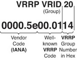
Figure 8-5 VRRP Virtual MAC Address
Object Tracking
Object tracking is a feature that most organizations will deploy when using VRRP. By default, VRRP will only detect a failure of the device itself or the path that is used by the hello packets. What about the uplinks from the routers running VRRP? If they fail, hello packets are still exchanged successfully, and the virtual master router is still available. Therefore, if the uplink is down, packets are dropped at the virtual master router because it cannot forward them. This is where object tracking comes into play. Object tracking enables you to control the priority of a router in a VRRP group based on the status of an object. The object can be IP-related information such as a route, a group of objects, the status of an SLA probe, and the status of an interface. If the object is anything but up, the priority of the router can be decremented to a value that is lower than the standby router, and because preemption is enabled by default, the standby router will take over as the virtual master router because it now has the higher priority. You can use the show vrrp command to verify whether object tracking is configured, as shown in Example 8-39, and the state of the tracked object.
Example 8-39 show vrrp Command Output on Router SW2
SW2#show vrrp
VLAN 20 - Group 20
State is Backup
Virtual IP address is 10.1.1.126
Virtual MAC address is 0000.5e00.0114
Advertisement interval is 1.000 sec
Preemption enabled
Priority is 99 (cfgd 110)
Track object 1 state Down decrement 11
Master Router is 10.1.1.65, priority is 100
Master Advertisement interval is 1.000 sec
Master Down interval is 3.570 sec (expires in 3.026 sec)
In the case of Example 8-39, you can see that the tracked object 1 is in a state of down, and when it is down, it will decrement the priority by 11. You can see the current priority is 99 and the configured priority is 110 (110 – 11 = 99).
However, you need to find out what the tracked object is specifically so that you can troubleshoot further. Using the command show track you can verify what tracked object number 1 is tracking. In Example 8-40, you can verify that it is the status of the line protocol on interface Gigabit Ethernet 1/0/10. It is admin-down and being tracked by VRRP group 20.
Example 8-40 show track Command Output on Router SW2
SW2#show track
Track 1
Interface GigabitEthernet1/0/10 line-protocol
Line protocol is Down (hw admin-down)
2 changes, last change 00:05:13
Tracked by:
VRRP VLAN20 20
Now you would have to troubleshoot why the interface is down, which is beyond the scope of our VRRP discussion.
Verifying First Hop
Once you know the current VRRP configuration, you might then check to see whether a host on the VRRP virtual IP address’s subnet can ping the virtual IP address. Based on the topology previously shown in Figure 8-4, Example 8-41 shows a successful ping from PC1.
Example 8-41 Ping Test from PC1 to the VRRP Virtual IP Address
C:\PC1>ping 10.1.1.66
Pinging 10.1.1.66 with 32 bytes of data:
Reply from 10.1.1.66: bytes=32 time=2ms TTL=255
Reply from 10.1.1.66: bytes=32 time=1ms TTL=255
Reply from 10.1.1.66: bytes=32 time=1ms TTL=255
Reply from 10.1.1.66: bytes=32 time=1ms TTL=255
Ping statistics for 10.1.1.66:
Packets: Sent = 4, Received = 4, Lost = 0 (0% loss),
Approximate round trip times in milli-seconds:
Minimum = 1ms, Maximum = 2ms, Average = 1ms
However, that does not prove that we are using the virtual MAC address and VRRP. Therefore, from the client, you should also verify the virtual MAC address learned by the client corresponds to the virtual MAC address reported by the VRRP virtual router master. Example 8-42 shows Workstation A’s ARP cache entry for the VRRP virtual IP address of 10.1.1.66. Notice in the output that the MAC address learned via ARP does match the VRRP virtual MAC address of the master router.
Example 8-42 PC1 ARP Cache
C:\PC1>arp -a
Interface: 10.1.1.74 --- 0x4
Internet Address Physical Address Type
10.1.1.66 00-00-5e-00-01-14 dynamic
However, as discussed with HSRP, one of the best tools to use with FHRPs to verify the path is traceroute. With traceroute, you can identify the physical first-hop router that the packets are traversing. Example 8-43 displays the tracert command executed on PC1. Notice that it states that the first hop is 10.1.1.66. This is the IP address of SW2’s VLAN 20 SVI. Therefore, you can conclude the SW2 is the virtual router master at the moment. Suppose, however, that a failure happened and SW1 became the virtual router master. The ARP cache would still be the same on PC1; however, the output of tracert on the PC would now display that the first hop is 10.1.1.65, as shown in Example 8-44.
Example 8-43 A Trace from PC1 Confirming That SW2 Is the First Hop (Virtual Router Master)
C:\PC1>tracert 192.0.2.1
Tracing route to 192.0.2.1 over a maximum of 30 hops
1 7 ms <1 ms 2 ms 10.1.1.66
...output omitted...
Trace complete.
Example 8-44 A Trace from PC1 Confirming That SW1 Is the First Hop (Virtual Router Master)
C:\PC1>tracert 192.0.2.1
Tracing route to 192.0.2.1 over a maximum of 30 hops
1 7 ms <1 ms 2 ms 10.1.1.65
...output omitted...
Trace complete.
VRRP Trouble Tickets
This section presents various trouble tickets relating to the topics discussed earlier in the chapter. The purpose of these trouble tickets is to give a process that you can follow when troubleshooting in the real world or in an exam environment. All trouble tickets in this section are based on the topology depicted in Figure 8-6.
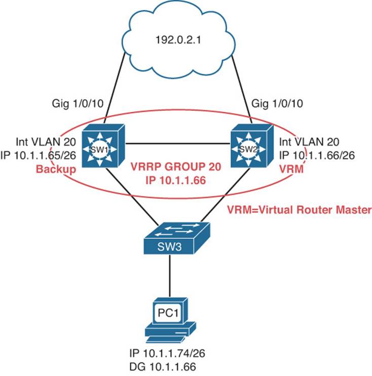
Figure 8-6 VRRP Trouble Ticket Topology
Trouble Ticket 8-4
Problem: According to traffic statistics, all traffic for VLAN 20 is flowing through SW1 to reach the core instead of SW2.
You start by verifying the problem from PC1 on VLAN 20. In this case, the best tool is traceroute because it will identify the router hops (real IPs) along the path. All you care about is the first hop; is it 10.1.1.65 or 10.1.1.66? This will identify whether traffic is flowing though SW1 or SW2 to reach the core. Example 8-45 indicates that SW1 should be the VRRP virtual router master for the 10.1.1.64/26 network, because it was the first hop returned for the tracert command.
Example 8-45 A Trace from PC1 Confirming That SW1 Is the First Hop (Master)
C:\PC1>tracert 192.0.2.1
Tracing route to 192.0.2.1 over a maximum of 30 hops
1 2 ms 2 ms 1 ms 10.1.1.65
...output omitted...
Trace complete.
Next you need to confirm that this is in fact true by reviewing the output of VRRP show commands. Example 8-46 displays the output of show vrrp brief on SW1. Notice that under the State column it states Backup and the Master addr is 10.1.1.66, which is also the virtual IP address for the group. Therefore, SW1 is not the VRRP master, even though it is being used as the first hop.
Example 8-46 show vrrp brief Command Output on SW1
SW1#show vrrp brief
Interface Grp Pri Time Own Pre State Master addr Group addr
Vl20 20 100 3609 Y Backup 10.1.1.66 10.1.1.66
Reviewing Figure 8-6 indicates that SW2 should be the virtual router master of the group, and it appears that it is. Now is an excellent time to review the output of show vrrp brief on SW2 to verify this. Example 8-47 indicates that SW2 is in the master state.
Example 8-47 show standby brief Command Output on SW2
SW2#show vrrp brief
Interface Grp Pri Time Own Pre State Master addr Group addr
Vl20 20 255 3003 Y Y Master 10.1.1.66 10.1.1.66
What would be causing SW1 and SW2 to be in their correct states, yet the wrong device being used as the first hop? Recall that when a client makes an ARP request for the VRRP group MAC address, the virtual router master will respond with the group MAC address. In this case, it should be 0000.5e00.0114 for group 20. On PC1, you issue the arp -a command, as shown in Example 8-48, to verify the MAC address being used by the client for the 10.1.1.66 address. It does not appear that the client is learning a VRRP MAC address, because none of the MAC addresses listed start with 0000.5e00.01. Also notice how the Internet address listed is 10.1.1.65, with a MAC of 28-93-fe-3a-e3-43. That is the IP and MAC address of interface VLAN 20 on SW1, as shown in Example 8-49, which displays the output of the show interface vlan 20 command.
Example 8-48 Verifying PC1’s ARP Cache
C:\PC1>arp -a
Interface: 10.1.1.74 --- 0x2
Internet Address Physical Address Type
10.1.1.65 28-93-fe-3a-e3-43 dynamic
Example 8-49 Verifying SW1’s SVI IP Address and MAC Address
SW1#show interface vlan 20
Vlan20 is up, line protocol is up
Hardware is EtherSVI, address is 2893.fe3a.e343 (bia 2893.fe3a.e343)
Internet address is 10.1.1.65/26
...output omitted...
It appears that the PCs might be configured with the wrong default gateway IP address. From the show commands you just reviewed, it seems as if they are using 10.1.1.65 as the default gateway address instead of the VRRP virtual IP of 10.1.1.66. Using the command ipconfig on PC1, you confirm that the default gateway is 10.1.1.65 and not 10.1.1.66, as shown in Example 8-50.
Example 8-50 Verifying the Default Gateway on PCs
C:\PC1>ipconfig
Windows IP Configuration
Ethernet adapter PC1:
Connection-specific DNS Suffix . :
IP Address. . . . . . . . . . . . : 10.1.1.74
Subnet Mask . . . . . . . . . . . : 255.255.255.192
IP Address. . . . . . . . . . . . : 2001:20::20
IP Address. . . . . . . . . . . . : fe80::a00:27ff:fea2:ce47%4
Default Gateway . . . . . . . . . : 10.1.1.65
You contact the administrator of the DHCP server and inform him of the issue. After the adjustments are made and the clients have the correct default gateway, as shown in Example 8-51, you reissue the tracert command and confirm that SW2 (10.1.1.66) is being used as the first hop, as shown in Example 8-51 as well.
Example 8-51 Verifying the Default Gateway on PCs After Adjustments
C:\PC1>ipconfig
Windows IP Configuration
Ethernet adapter PC1:
Connection-specific DNS Suffix . :
IP Address. . . . . . . . . . . . : 10.1.1.74
Subnet Mask . . . . . . . . . . . : 255.255.255.192
IP Address. . . . . . . . . . . . : 2001:20::20
IP Address. . . . . . . . . . . . : fe80::a00:27ff:fea2:ce47%4
Default Gateway . . . . . . . . . : 10.1.1.66
C:\PC1>tracert 192.0.2.1
Tracing route to 192.0.2.1 over a maximum of 30 hops
1 3 ms 1 ms 2 ms 10.1.1.66
...output omitted...
Trace complete.
However, it is important that you confirm the correct VRRP MAC address is being used by checking the ARP cache on the PCs. In Example 8-52, you confirm with the arp -a command that the MAC address of 0000.5e00.0114 for group 20 is being used.
Example 8-52 Verifying PC1’s ARP Cache After Adjustments
C:\PC1>arp -a
Interface: 10.1.1.74 --- 0x2
Internet Address Physical Address Type
10.1.1.66 00-00-5e-00-01-14 dynamic
Trouble Ticket 8-5
Problem: According to traffic statistics, when the uplink between SW3 and SW2 goes down, all traffic for VLAN 20 is flowing through SW3, SW1, and then SW2 and routed out to the core, as shown in Figure 8-7. (Note that the default gateway IP address differs from the previous figures.)
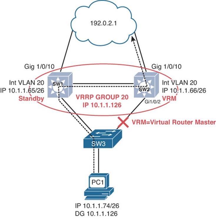
Figure 8-7 VRRP Suboptimal Traffic Flow Topology
If the uplink between SW3 and SW2 is not available, SW1 should become the VRRP virtual router master so that traffic flow is optimized in the LAN.
You start verifying the problem by shutting down the link between SW3 and SW2. You then trace the path from PC1 to an IP address outside the LAN. All you care about is the first hop; is it 10.1.1.65 or 10.1.1.66? This will identify whether traffic is flowing though SW1 or SW2 to reach the core. Example 8-53 indicates that SW2 is in fact the VRRP virtual router master for the 10.1.1.64/26 network, because it was the first hop returned for the tracert command.
Example 8-53 A Trace from PC1 Confirming That SW2 Is the First Hop (Master)
C:\PC1>tracert 192.0.2.1
Tracing route to 192.0.2.1 over a maximum of 30 hops
1 2 ms 2 ms 2 ms 10.1.1.66
...output omitted...
Trace complete.
Next you need to confirm that this is in fact true by reviewing the output of VRRP show commands. Example 8-54 displays the output of show vrrp brief on SW2. Notice that under the State column it states Master and the Master addr is 10.1.1.66 (SW2) for the group address 10.1.1.126. All looks fine so far.
Example 8-54 show vrrp brief Command Output on SW2
SW2#show vrrp brief
Interface Grp Pri Time Own Pre State Master addr Group addr
Vl20 20 100 3570 Y Master 10.1.1.66 10.1.1.126
Next you review the output of show vrrp, as shown in Example 8-55. In this output, you notice that SW2 is the master but that there is a problem with the priority. The configured priority is 110, but the current is 100. As a result, it has been decremented dynamically. This can be verified with the tracked object that is currently down. It indicates that the tracking object 1 is down, and when it is down, the priority will be decremented by 10 (110 – 10 = 100).
Example 8-55 show vrrp Command Output on SW2
SW2#show vrrp
Vlan20 - Group 20
State is Master
Virtual IP address is 10.1.1.126
Virtual MAC address is 0000.5e00.0114
Advertisement interval is 1.000 sec
Preemption enabled
Priority is 100 (cfgd 110)
Track object 1 state Down decrement 10
Master Router is 10.1.1.66 (local), priority is 100
Master Advertisement interval is 1.000 sec
Master Down interval is 3.570 sec
What is tracking object 1? To verify, you execute the show track command on SW2. As Example 8-56 displays, the output of show track indicates that you are tracking the line protocol of Gigabit Ethernet 1/0/2 for VRRP on interface VLAN 20 for group 20. At this point in time, Gigabit Ethernet 1/0/2 is down, and as a result, VRRP decremented the priority by 10, as you saw in Example 8-55. However, SW2 is still the virtual router master for group 20 even though the priority is being decremented.
Example 8-56 show track Command Output on SW2
SW2#show track
Track 1
Interface GigabitEthernet1/0/2 line-protocol
Line protocol is Down (hw down)
6 changes, last change 01:39:45
Tracked by:
VRRP Vlan20 20
Next you verify the priority on SW1 with the show vrrp command, as shown in Example 8-57. The output clearly shows that the priority of SW1 is 100, which is the same as SW2. Reviewing the output of show vrrp for SW1 and SW2 identifies that preemption is enabled. If that is the case, and the priority is tied, why is SW2 the virtual router master? When priority is tied, the IP address of the LAN interface participating in VRRP is used as the tiebreaker, just like HSRP. Because SW2 has the higher LAN IP address, it is the virtual router master.
Example 8-57 show vrrp Command Output on SW1
SW1#show vrrp
Vlan20 - Group 20
State is Backup
Virtual IP address is 10.1.1.126
Virtual MAC address is 0000.5e00.0114
Advertisement interval is 1.000 sec
Preemption enabled
Priority is 100
Master Router is 10.1.1.66, priority is 100
Master Advertisement interval is 1.000 sec
Master Down interval is 3.609 sec (expires in 3.575 sec)
How can you make sure that SW1 takes over as the virtual router master if the uplink between SW3 and SW2 fails? In this case, make sure that the priority of SW2 is dropped below that of SW1. On SW2, you issue the vrrp track 1 decrement 11 command in interface VLAN 20 configuration mode. As soon as you do this, a syslog message is displayed on SW2, as follows:
%VRRP-6-STATECHANGE: Vl20 Grp 20 state Master -> Backup
On SW1, the following syslog message is displayed:
%VRRP-6-STATECHANGE: Vl20 Grp 20 state Backup -> Master
You now reissue the tracert command on PC1 to verify the first hop. It is now SW1, as shown in Example 8-58.
Example 8-58 A Trace from PC1 Confirming That SW1 Is the First Hop (Master)
C:\PC1>tracert 192.0.2.1
Tracing route to 192.0.2.1 over a maximum of 30 hops
1 2 ms 2 ms 2 ms 10.1.1.65
...output omitted...
Trace complete.
Next you enable the interface between SW3 and SW2 with the no shutdown command and receive the following syslog message on SW2:
%TRACKING-5-STATE: 1 interface Gi1/0/2 line-protocol Down->Up
%VRRP-6-STATECHANGE: Vl20 Grp 20 state Backup -> Master
Because the interface is up, the tracking object is up, which means that SW2’s priority goes back to 110, and SW2 becomes the virtual router master. You then reissue the tracert command on PC1 to verify the first hop. It is now SW2, as shown in Example 8-59.
Example 8-59 A Trace from PC1 Confirming That SW2 Is the First Hop (Master)
C:\PC1>tracert 192.0.2.1
Tracing route to 192.0.2.1 over a maximum of 30 hops
1 2 ms 2 ms 2 ms 10.1.1.66
...output omitted...
Trace complete.
Troubleshooting GLBP
Whereas HSRP can only have one active forwarder for each group, Gateway Load Balancing Protocol (GLBP) can have multiple forwarders for each group. Therefore, GLBP can load balance traffic destined for a next-hop gateway across a collection of routers within the GLBP group.
This section explains the GLBP active virtual gateway (AVG) and active virtual forwarder (AVF) concepts and how to verify and troubleshoot issues related to GLBP.
Reviewing GLBP
With GLBP, there is one AVG and up to four AVFs in a group. The AVG is responsible for handing out the AVF MAC addresses to the hosts in the LAN. Therefore, it is responsible for replying to ARP requests for the MAC address of the default gateway. Note that the AVG is usually an AVF as well. The AVFs are responsible for processing the frames that are sent to their MAC address.
Figure 8-8 shows a GLBP topology example. R1 is the AVG, and R1 and R2 are AVFs. The virtual router IP address that will be used as the default gateway on all the hosts is 10.1.1.62. When Workstation A sends an ARP request for the MAC address of 10.1.1.62, R1 (AVG) responds with the MAC of 0007.b400.0a01. When Workstation B sends an ARP request for the MAC address of 10.1.1.62, R1 (AVG) responds with the MAC of 0007.b400.0a02. The next workstation that sends an ARP request will get 0007.b400.0a01 and then 0007.b400.0a02, and so on. This is the default behavior known as round-robin, which can be changed with the glbp group_id load-balancing interface configuration command. The other options are host-dependent and weighted.
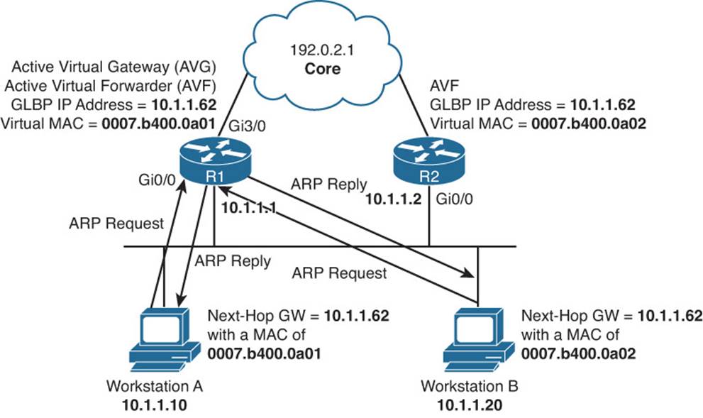
Figure 8-8 Basic GLBP Operation
As you can see from Figure 8-8, Workstation A sends default gateway destined traffic to R1, and Workstation B sends default gateway destined traffic to R2.
Examples 8-60 and 8-61 show the possible GLBP configurations for routers R1 and R2.
Example 8-60 Possible GLBP Configuration on Router R1
R1#show run interface gigabitethernet 0/0
Building configuration...
Current configuration : 269 bytes
!
interface GigabitEthernet0/0
ip address 10.1.1.1 255.255.255.192
glbp 10 ip 10.1.1.62
glbp 10 priority 150
glbp 10 preempt
glbp 10 weighting 110 lower 90 upper 100
glbp 10 load-balancing weighted
end
Example 8-61 Possible GLBP Configuration on Router R2
R2#show run interface gigabitethernet 0/0
Building configuration...
Current configuration : 237 bytes
!
interface GigabitEthernet0/0
ip address 10.1.1.2 255.255.255.192
glbp 10 ip 10.1.1.62
glbp 10 preempt
glbp 10 weighting 100 lower 80
glbp 10 load-balancing weighted
end
Notice that both routers R1 and R2 have been configured with the same virtual IP address of 10.1.1.62 for GLBP group 10. Router R1 is configured to be the AVG with a higher priority using the glbp 10 priority 150 command. Router R2 has a default GLBP priority of 100, and with GLBP, higher-priority values are more preferable. Also, notice that both routers are configured with the glbp 10 preempt command. This ensures that the router with the higher priority will be the AVG. Remember that preemption is not enabled by default for the AVG election process.
The last two commands in Examples 8-60 and 8-61 relate to the AVFs and how their MAC addresses will be handed out to hosts on the LAN by the AVG, and whether they will be allowed to forward traffic. By default, the MACs will be handed out in a round-robin fashion. However, in these examples, load balancing has been configured to weighted. This means that the initial weighting value defined in the glbp 10 weighting command will determine the ratio that will be used to hand out MAC addresses. In this case, the AVG will hand out the MAC addresses in a 110:100 ratio, or 11:10 ratio. This means that R1’s virtual MAC address will be given to clients 11 times for every 10 times that R2’s virtual MAC address will be given out. Therefore, R1 will handle more hosts on average than R2. The lower and upper values are related to when the AVF will lose its ability to forward traffic for its virtual MAC address and when it will regain its ability to forward traffic for its virtual MAC address. Referring to Example 8-60 again, notice that R1’s lower limit is 90. This means that R1 will lose its ability to forward traffic for its virtual MAC address if its weighting drops below 90. It will regain its ability to forward traffic for its virtual MAC address if its weighting goes back above 100. The initial weighing value is 110. Notice that R2 in Example 8-61 has no upper weighting, which means that it is the same as the initial weighting.
GLBP Verification and Troubleshooting
When verifying a GLBP configuration or troubleshooting a GLBP issue, begin by determining the following information about the GLBP group under inspection:
![]() Which router is the AVG?
Which router is the AVG?
![]() Which routers are the AVFs?
Which routers are the AVFs?
![]() How was the AVG chosen?
How was the AVG chosen?
![]() Which routers, if any, are configured with the preempt option?
Which routers, if any, are configured with the preempt option?
![]() What is the IP address of the virtual router?
What is the IP address of the virtual router?
![]() What are the AVFs virtual MAC addresses?
What are the AVFs virtual MAC addresses?
![]() Is object tracking on?
Is object tracking on?
The show glbp brief command displays a great deal of GLBP information. Examples 8-62 and 8-63 provide samples of the show glbp brief command. The output identifies the interfaces that are participating in a GLBP group. It identifies who the AVFs are under the Fwd column. The – refers to the AVG information, and the numbers 1 and 2 refer to the AVFs in the group. The Priority column is used to display the priority used during the AVG election process. The State column identifies the state of the device for the group. If it is the AVG row, in this case the top row, active means that it is the AVG, and standby means that it is waiting to become the AVG if the AVG fails. For the second and third rows, it is referring to the state of the AVF. In these examples, active means that the router is forwarding for the virtual MAC address in the Address column. Listen means that the router is waiting to take over the forwarding process for the virtual MAC address in the Address column if the router listed in the Active Router column is no longer able to forward traffic for the virtual MAC address.
Example 8-62 show glbp brief Command Output on Router R1
R1#show glbp brief
Interface Grp Fwd Pri State Address Active router Standby router
Gi0/0 10 - 150 Active 10.1.1.62 local 10.1.1.2
Gi0/0 10 1 - Active 0007.b400.0a01 local -
Gi0/0 10 2 - Listen 0007.b400.0a02 10.1.1.2 -
Example 8-63 show glbp brief Command Output on Router R2
R2#show glbp brief
Interface Grp Fwd Pri State Address Active router Standby router
Gi0/0 10 - 100 Standby 10.1.1.62 10.1.1.1 local
Gi0/0 10 1 - Listen 0007.b400.0a01 10.1.1.1 -
Gi0/0 10 2 - Active 0007.b400.0a02 local -
The show glbp command output provides significant details about the GLBP groups, as shown in Example 8-64. In the output, you can verify the group number and the interface associated with it. You can determine whether it is the AVG based on whether it is active or standby. The virtual IP address, the hello and hold timers, and the status of preemption is also listed. Depending on the state of the device, you will be able to verify the active or standby routers IP address and its priority. You will also be able to see your current local priority and the configured priority. This is a great command to verify the weighting values, the type of load balancing being used, and the members of the group, which are identified by their physical MAC address and IP address associated with the interface participating in the GLBP group.
Example 8-64 show glbp Command Output on Router R1
R1#show glbp gigabitethernet0/0
GigabitEthernet0/0 - Group 10
State is Active
1 state change, last state change 00:31:34
Virtual IP address is 10.1.1.62
Hello time 3 sec, hold time 10 sec
Next hello sent in 1.568 secs
Redirect time 600 sec, forwarder time-out 14400 sec
Preemption enabled, min delay 0 sec
Active is local
Standby is 10.1.1.2, priority 100 (expires in 9.984 sec)
Priority 150 (configured)
Weighting 110 (configured 110), thresholds: lower 90, upper 100
Track object 1 state Up decrement 25
Load balancing: weighted
Group members:
ca12.0854.0008 (10.1.1.2)
ca13.0854.0008 (10.1.1.1) local
There are 2 forwarders (1 active)
Forwarder 1
State is Active
3 state changes, last state change 00:03:35
MAC address is 0007.b400.0a01 (default)
Owner ID is ca13.0854.0008
Redirection enabled
Preemption enabled, min delay 30 sec
Active is local, weighting 110
Forwarder 2
State is Listen
MAC address is 0007.b400.0a02 (learnt)
Owner ID is ca12.0854.0008
Redirection enabled, 600.000 sec remaining (maximum 600 sec)
Time to live: 14400.000 sec (maximum 14400 sec)
Preemption enabled, min delay 30 sec
Active is 10.1.1.2 (primary), weighting 100 (expires in 11.232 sec)
Still referring to Example 8-64, focus on the area related to the forwarders. This information is related to the AVFs in the group. In this case, you can verify that there are two AVFs. This router is currently active for Forwarder 1, meaning that it is forwarding for the MAC address 0007.b400.0a01 that is listed. It also states who the current owner is of the virtual MAC address, based on the physical MAC address of the device. The owner is the device currently responsible for forwarding traffic for the virtual MAC address. R1 is in the listen state for Forwarder 2, meaning that it is waiting for the current owner of the virtual MAC 0007.b400.0a02 to no longer be able to forward for the MAC so that it can take over.
Virtual Router MAC Addresses
The default virtual MAC address for the AVFs in a GLBP group, as shown in Figure 8-9, is based on the group number and the AVF forwarder ID within the group. Specifically, the virtual MAC address for a GLBP group begins with a well-known GLBP code of 0007.b400. The next two hexadecimal digits represent the group number. The last two hexadecimal digits represent the forwarder ID within the group. For example, a GLBP group of 43 yields a default virtual MAC address for AVF 1 of 0007.b400.2b01, because 43 in decimal equates to 2b in hexadecimal. For AVF 2, it would be 0007.b400.2b02, and for AVF 3, it would be 0007.b400.2b03.
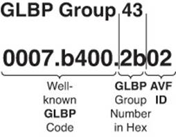
Figure 8-9 GLBP Virtual MAC Address
GLBP Object Tracking
As with VRRP, you can implement object tracking. By default, GLBP will only detect a failure of the device itself or the path that is used by the hello packets. That is perfectly fine for the AVG because a failure of an uplink outside the LAN will not affect the AVG because hello packets are still exchanged successfully, and the AVG is still reachable. However, what about the AVFs? If the uplinks fail, the AVF cannot forward packets for the virtual IP and MAC it owns. This is where object tracking comes into play for the AVFs. Object tracking allows you to control the weighting of an AVF in a GLBP group based on the status of an object. The object can be IP-related information such as a route, a group of objects, the status of an SLA probe, and the status of an interface. If the object is anything but up, the weight of the router can be decremented to a value that is lower than a configured threshold so that another AVF can forward on behalf of the router that cannot. You can use the show glbp command to verify whether object tracking is configured, as shown in Example 8-65, and the state of the tracked object.
Example 8-65 show glbp Command Output on Router R1
R1#show glbp
GigabitEthernet0/0 - Group 10
State is Active
1 state change, last state change 00:31:34
Virtual IP address is 10.1.1.62
Hello time 3 sec, hold time 10 sec
Next hello sent in 1.568 secs
Redirect time 600 sec, forwarder time-out 14400 sec
Preemption enabled, min delay 0 sec
Active is local
Standby is 10.1.1.2, priority 100 (expires in 9.984 sec)
Priority 150 (configured)
Weighting 110 (configured 110), thresholds: lower 90, upper 100
Track object 1 state Up decrement 25
Load balancing: weighted
Group members:
ca12.0854.0008 (10.1.1.2)
ca13.0854.0008 (10.1.1.1) local
There are 2 forwarders (1 active)
Forwarder 1
State is Active
3 state changes, last state change 00:03:35
MAC address is 0007.b400.0a01 (default)
Owner ID is ca13.0854.0008
Redirection enabled
Preemption enabled, min delay 30 sec
Active is local, weighting 110
Forwarder 2
State is Listen
MAC address is 0007.b400.0a02 (learnt)
Owner ID is ca12.0854.0008
Redirection enabled, 600.000 sec remaining (maximum 600 sec)
Time to live: 14400.000 sec (maximum 14400 sec)
Preemption enabled, min delay 30 sec
Active is 10.1.1.2 (primary), weighting 100 (expires in 11.232 sec)
In the case of Example 8-65, you can see that the tracked object 1 is in a state of up. However, if the tracked object goes down, the weighting will be decremented by 25, and as a result, the weighting will be lower than the lower threshold of 90 and R1 will no longer be able to be the AVF for MAC 0007.b400.0a01. AVF2, which is R2, will have to forward for both MAC addresses at this point.
However, if you need to find out what the tracked object is specifically so that you can troubleshoot further, use the command show track, as shown in Example 8-66. In this output, the line protocol of interface Gigabit Ethernet 3/0 is being tracked by GLBP.
Example 8-66 show track Command Output on R1
R1#show track
Track 1
Interface GigabitEthernet3/0 line-protocol
Line protocol is Up
3 changes, last change 00:05:56
Tracked by:
GLBP GigabitEthernet0/0 10
Verifying GLBP First Hop
Once you know the current GLBP configuration, you might then check to see whether a host on the GLBP virtual IP address’s subnet can ping the virtual IP address. Based on the topology previously shown in Figure 8-8, Example 8-67 shows a successful ping from Workstation A.
Example 8-67 Ping Test from Workstation A to the GLBP Virtual IP Address
C:\>ping 10.1.1.62
Pinging 10.1.1.62 with 32 bytes of data:
Reply from 10.1.1.62: bytes=32 time=2ms TTL=255
Reply from 10.1.1.62: bytes=32 time=1ms TTL=255
Reply from 10.1.1.62: bytes=32 time=1ms TTL=255
Reply from 10.1.1.62: bytes=32 time=1ms TTL=255
Ping statistics for 10.1.1.62:
Packets: Sent = 4, Received = 4, Lost = 0 (0% loss),
Approximate round trip times in milli-seconds:
Minimum = 1ms, Maximum = 2ms, Average = 1ms
However, that does not prove that we are using the virtual MAC address and GLBP successfully. Therefore, from the client, you should also verify that the virtual MAC address learned by the client corresponds to the virtual MAC address reported by the GLBP AVG. Example 8-68 shows Workstation A’s ARP cache entry for the GLBP virtual IP address of 10.1.1.62. Notice in the output that the MAC address learned via ARP does match the GLBP virtual MAC address of the first AVF.
Example 8-68 Workstation A’s ARP Cache
C:\>arp -a
Interface: 10.1.1.10 --- 0x4
Internet Address Physical Address Type
10.1.1.62 00-07-b4-00-0a-01 dynamic
However, as discussed with HSRP and VRRP, one of the best tools to use with FHRPs to verify the path is traceroute. With traceroute, you can identify the physical first-hop router that the packets are traversing. Example 8-69 displays the tracert command executed on Workstation A. Notice that it states that the first hop is 10.1.1.1. This is the IP address of R1’s Gig0/0 interface. Example 8-70 displays the tracert command executed on Workstation B. Notice that it states that the first hop is 10.1.1.2. This is the IP address on R2’s Gig0/0 interface. But remember in both cases they are configured to use the virtual IP 10.1.1.62 and are dynamically provided a virtual MAC address based on the AVG load-balancing method.
Example 8-69 A Trace from Workstation A Confirming That R1 Is the First Hop (AVF)
C:\>tracert 192.0.2.1
Tracing route to 192.0.2.1 over a maximum of 30 hops
1 2 ms 2 ms 2 ms 10.1.1.1
...output omitted...
Trace complete.
Example 8-70 A Trace from Workstation B Confirming That R2 Is the First Hop (AVF)
C:\>tracert 192.0.2.1
Tracing route to 192.0.2.1 over a maximum of 30 hops
1 2 ms 2 ms 2 ms 10.1.1.2
...output omitted...
Trace complete.
GLBP Trouble Tickets
This section presents various trouble tickets relating to the topics discussed earlier in the chapter. The purpose of these trouble tickets is to give a process that you can follow when troubleshooting in the real world or in an exam environment. All trouble tickets in this section are based on the topology depicted in Figure 8-10.
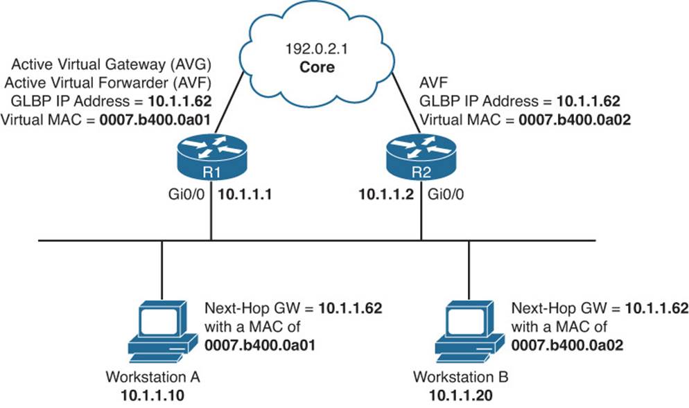
Figure 8-10 GLBP Trouble Ticket Topology
Trouble Ticket 8-6
Problem: A junior administrator has stated that GLBP is behaving strangely.
With a puzzled look on your face, you ask the junior admin to show you what she means. The junior admin provides the output shown in Example 8-71 and Example 8-72. You review them, and then ask the junior administrator to explain.
Example 8-71 Output of show glbp brief on R1
R1#show glbp brief
Interface Grp Fwd Pri State Address Active router Standby router
Gi0/0 10 - 150 Active 10.1.1.62 local unknown
Gi0/0 10 1 - Active 0007.b400.0a01 local -
Gi0/0 10 2 - Active 0007.b400.0a02 local -
Example 8-72 Output of show glbp brief on R2
R2#show glbp brief
Interface Grp Fwd Pri State Address Active router Standby router
Gi0/0 10 - 100 Active 10.1.1.62 local unknown
Gi0/0 10 1 - Active 0007.b400.0a01 local -
Gi0/0 10 2 - Active 0007.b400.0a02 local -
The junior administrator indicates that R1 and R2 are both in group 10. R1 has a priority of 150, and R2 has a priority of 100. However, they are both indicating that they are the AVG for the virtual address 10.1.1.62. In addition, R1 and R2 are both stating that they are the AVFs for the MAC addresses listed.
You then ask the junior admin, “Why would they both consider themselves as the AVG and AVFs?” The junior admin replies, “They don’t know each other is on the LAN and participating in GLBP group 10.” You grin and state, “That is correct. Now find out why!”
The junior admin issues the command show glbp on R1 and R2, as displayed in Examples 8-73 and 8-74, and reviews them hoping to spot the difference. The output confirms that both R1 and R2 are the AVG for group 10 because it states “State is Active” near the top. The virtual IP is the same at 10.1.1.62. The timers are the same, although they do not have to be as long as they do not cause flapping neighbor relationships. At this point, the junior admin spots the difference. Do you see it?
Example 8-73 Output of show glbp on R1
R1#show glbp brief
GigabitEthernet0/0 - Group 10
State is Active
3 state changes, last state change 00:23:29
Virtual IP address is 10.1.1.62
Hello time 3 sec, hold time 10 sec
Next hello sent in 0.288 secs
Redirect time 600 sec, forwarder time-out 14400 sec
Authentication text, string "TSHOOT"
Preemption enabled, min delay 0 sec
Active is local
Standby is unknown
Priority 150 (configured)
...output omitted...
Example 8-74 Output of show glbp on R2
R2#show glbp brief
GigabitEthernet0/0 - Group 10
State is Active
8 state changes, last state change 00:21:32
Virtual IP address is 10.1.1.62
Hello time 3 sec, hold time 10 sec
Next hello sent in 2.592 secs
Redirect time 600 sec, forwarder time-out 14400 sec
Authentication MD5, key-string
Preemption enabled, min delay 0 sec
Active is local
Standby is unknown
Priority 100 (default)
... output omitted...
R1 is using plain-text GLBP authentication, and R2 is using message digest 5 (MD5) GLBP authentication. They are both using authentication, but the type of authentication does not match. Therefore, they know each other is there, but because they cannot authenticate each other, they consider each other to be rogue GLBP devices and will not accept the GLBP information from each other.
Your security policy states to use MD5 authentication, so you change R1 with the command glbp 10 authentication md5 key-string TSHOOT in interface configuration mode. You then check the output of show glbp brief on R1 and R2, as shown in Examples 8-75 and 8-76, to verify whether the output has changed. It has. R1 is the AVG and AVF for the first MAC, and R2 is standby and the AVF for the second MAC.
Example 8-75 Output of show glbp brief on R1
R1#show glbp brief
Interface Grp Fwd Pri State Address Active router Standby router
Gi0/0 10 - 150 Active 10.1.1.62 local 10.1.1.2
Gi0/0 10 1 - Active 0007.b400.0a01 local -
Gi0/0 10 2 - Listen 0007.b400.0a02 10.1.1.2 -
Example 8-76 Output of show glbp brief on R2
R2#show glbp brief
Interface Grp Fwd Pri State Address Active router Standby router
Gi0/0 10 - 100 Standby 10.1.1.62 10.1.1.1 local
Gi0/0 10 1 - Listen 0007.b400.0a01 10.1.1.1 -
Gi0/0 10 2 - Active 0007.b400.0a02 local -
Trouble Ticket 8-7
Problem: The uplink has failed between R2 and the core; however, R2 is still the AVF for MAC 0007.b400.0a02 when it should be R1.
Let’s shoot from the hip this time!
Brainstorm: Uplink failed + R2 still AVF when it should not be = object tracking and weight issue?
Let’s use the show glbp command to see what the weight of R2 is and whether object tracking is enabled. Example 8-77 displays the output of show glbp on R2, and it clearly indicates that we are tracking object 1, which is down, and when it is down, the weighting will be decremented by 20, which it has been because the configured weight is 100 and the current weight is 80. However, R2’s weighting still has not passed the lower threshold. Therefore, it will still be the AVF for the MAC address assigned to it by the AVG.
Example 8-77 Output of show glbp on R2
R2#show glbp
GigabitEthernet0/0 - Group 10
State is Standby
10 state changes, last state change 00:20:58
Virtual IP address is 10.1.1.62
Hello time 3 sec, hold time 10 sec
Next hello sent in 0.736 secs
Redirect time 600 sec, forwarder time-out 14400 sec
Authentication MD5, key-string
Preemption enabled, min delay 0 sec
Active is 10.1.1.1, priority 150 (expires in 8.480 sec)
Standby is local
Priority 100 (default)
Weighting 80 (configured 100), thresholds: lower 80, upper 100
Track object 1 state Down decrement 20
Load balancing: weighted
To solve this problem, you need to modify the glbp 10 weighting track 1 command so that the decrement is greater than 20 (for example, glbp 10 weighting track 1 decrement 21). When you do so, R1 will be the AVF for both MACs. On R1, you can confirm this with the show glbp briefcommand, as shown in Example 8-78.
Example 8-78 Output of show glbp brief on R1
R1#show glbp brief
Interface Grp Fwd Pri State Address Active router Standby router
Gi0/0 10 - 150 Active 10.1.1.62 local 10.1.1.2
Gi0/0 10 1 - Active 0007.b400.0a01 local -
Gi0/0 10 2 - Active 0007.b400.0a02 local -
Comparing HSRP, VRRP, and GLBP
As you have witnessed in this chapter, HSRP, VRRP, and GLBP are very similar. The output provided by the show commands is similar as well. It is important to note that the issues will be similar with these FHRPs, making them easy to troubleshoot for most. However, although HSRP, VRRP, and GLBP have commonalities, it is important for you as a troubleshooter to understand the differences to make sure that you are troubleshooting as efficiently as possible. Table 8-2 compares several characteristics of these FHRPs.
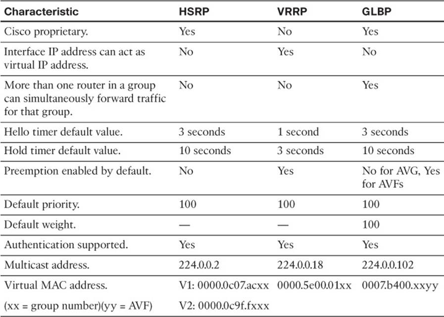
Table 8-2 Comparing HSRP, VRRP, and GLBP
Exam Preparation Tasks
As mentioned in the section “How to Use This Book” in the Introduction, you have a couple of choices for exam preparation: the exercises here; Chapter 22, “Final Preparation;” and the exam simulation questions on the CD-ROM.
Review All Key Topics
Review the most important topics in this chapter, noted with the Key Topic icon in the outer margin of the page. Table 8-3 lists a reference of these key topics and the page numbers on which each is found.
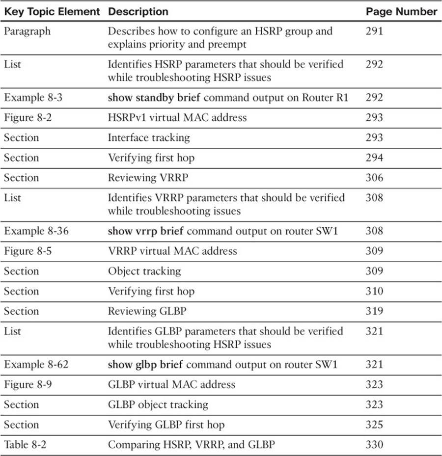
Table 8-3 Key Topics for Chapter 8
Define Key Terms
Define the following key terms from this chapter and check your answers in the glossary:
HSRP
VRRP
GLBP
priority
preempt
interface tracking
object tracking
virtual router
virtual MAC address
active forwarder
standby router
virtual master router
virtual router backup
AVG
AVF
weighting
Complete Tables and Lists from Memory
Print a copy of Appendix C, “Memory Tables,” (found on the disc), or at least the section for this chapter, and complete the tables and lists from memory. Appendix D, “Memory Tables Answer Key,” also on the disc, includes completed tables and lists to check your work.
Command Reference to Check Your Memory
This section includes the most important show commands covered in this chapter. It might not be necessary to memorize the complete syntax of every command, but you should be able to remember the basic keywords that are needed.
To test your memory of the commands, cover the right side of Table 8-4 with a piece of paper, read the description on the left side, and then see how much of the command you can remember.
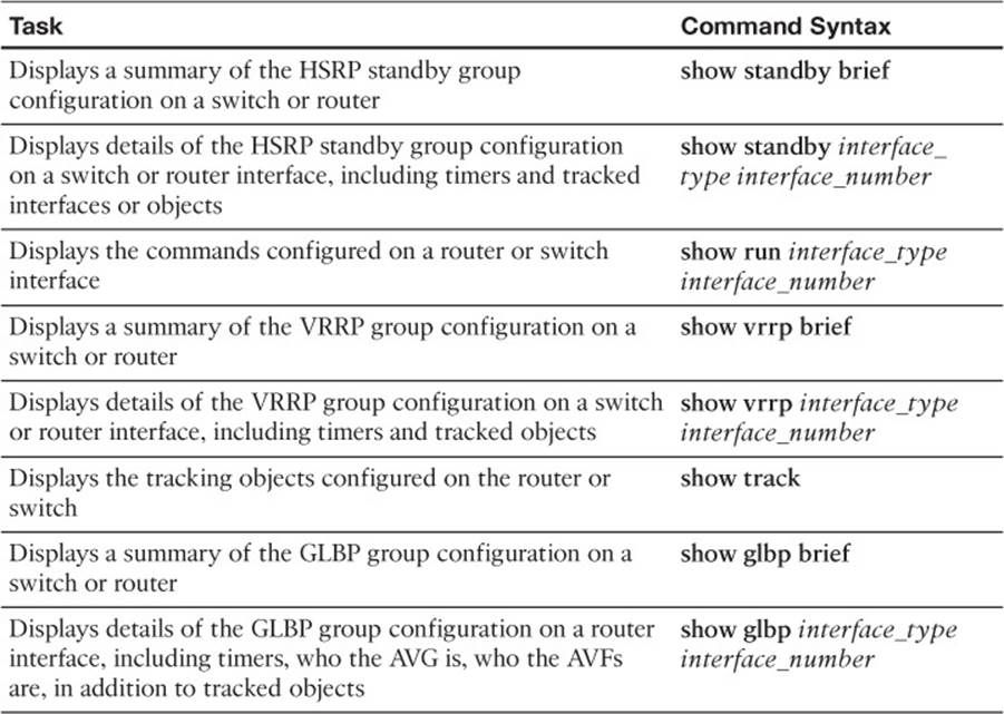
Table 8-4 show commands
The 300-135 TSHOOT exam focuses on practical, hands-on skills that are used by a networking professional. Therefore, you should be able to identify the commands needed to troubleshoot issues related to the topics covered in this chapter.
All materials on the site are licensed Creative Commons Attribution-Sharealike 3.0 Unported CC BY-SA 3.0 & GNU Free Documentation License (GFDL)
If you are the copyright holder of any material contained on our site and intend to remove it, please contact our site administrator for approval.
© 2016-2026 All site design rights belong to S.Y.A.