Sams Teach Yourself Arduino Programming in 24 Hours (2015)
Part II: The C Programming Language
Hour 12. Storing Data
What You’ll Learn in This Hour:
![]() How the Arduino handles data in your sketches
How the Arduino handles data in your sketches
![]() How to get the most use out of Arduino memory
How to get the most use out of Arduino memory
![]() How to store data long term on an Arduino
How to store data long term on an Arduino
One of the challenges of programming for the Arduino is that your sketches are limited by the resources available on the microcontroller. Nowhere is that more evident than when you try to handle large amounts of data. Because of the limited memory resources on the Arduino, you sometimes have to get a little creative in how you handle the data in your sketch. This hour shows some ways to help conserve memory in your sketches and shows how to utilize the extra EEPROM memory to store data for long-term use.
Arduino Memory Refresher
Hour 1, “Introduction to the Arduino,” showed the basics of how the Arduino memory structure works. The ATmega AVR microcontroller chips used in the Arduino family have three different types of built-in memory:
![]() Flash
Flash
![]() Static random-access memory (SRAM)
Static random-access memory (SRAM)
![]() Electronically erasable programmable read-only memory (EEPROM)
Electronically erasable programmable read-only memory (EEPROM)
The flash memory is where the Arduino stores the sketch executable code. Once you load your sketch into flash memory, it will remain there, even after you power off the Arduino. By default, the Arduino also installs a small bootloader program in flash memory, which assists in loading and starting your sketch each time you power on the Arduino.
The SRAM memory is where the Arduino stores the data used in your sketches. This is where any variable values that you define in your sketch are stored. The Arduino can access data in the SRAM memory area very quickly, but the downside is that the SRAM memory loses data when you turn off the power to the Arduino.
The EEPROM memory provides a long-term data storage solution for your Arduino sketches. Like the flash memory area, it retains any data that you store in the memory area after you remove power from the Arduino. This provides an area where you can store data that’s used between sessions.
However, there are a couple of limitations to utilizing the EEPROM memory area on the Arduino. First, storing data in EEPROM is a relatively slow process, compared to SRAM data access speeds. That can significantly slow down your sketch.
The second limitation is that there are a limited number of times you can write to an EEPROM before the stored data become unreliable. The general rule of thumb is that after about 100,000 writes to the EEPROM, there’s no guarantee that the data you write will get properly stored.
Table 12.1 shows the different sizes of flash, SRAM, and EEPROM available in the different Arduino units, based on the Atmel chip that they use.
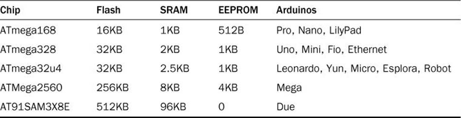
TABLE 12.1 Arduino Memory Sizes
For the standard Arduino Uno, you only have 2KB of SRAM memory to work with in your sketches. The next section takes a closer look at how the Arduino manages your sketch data in the SRAM memory area.
Did You Know?: External Memory
The Arduino also allows you to add external memory to your project. The most common type of external memory to use is adding another EEPROM chip for storing data. This can come in handy if your project requires more data storage than what’s available on the Arduino unit.
Taking a Closer Look at SRAM
The SRAM memory is the workhorse of the Arduino. It’s where your sketch stores all the data that it uses as it runs. The CPU in the Arduino microcontroller handles memory management on the Arduino automatically for us, but you can use some tricks to help it get the most out of your SRAM memory area.
The ATmega AVR microcontroller CPU utilizes a common two-tier approach to managing the variables that you create in your sketch. This two-tier method divides the SRAM memory into two separate areas:
![]() The heap data area
The heap data area
![]() The stack data area
The stack data area
Each of these memory data areas handle different types of data that you define in the sketch. Figure 12.1 shows how the Arduino positions the heap and stack data areas within SRAM.
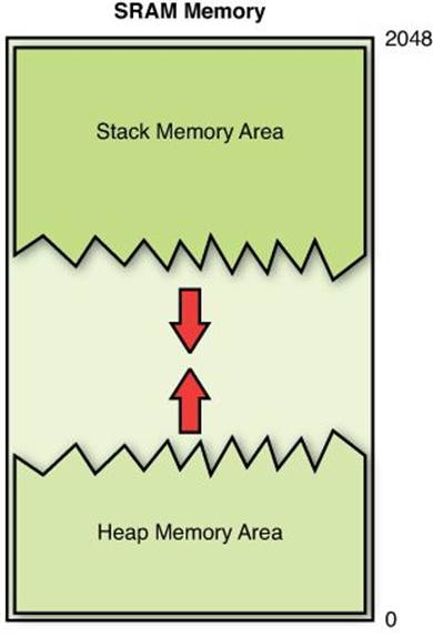
FIGURE 12.1 The Arduino SRAM heap and stack data areas.
The Arduino places the heap data area at the start of the SRAM memory area, and builds it upward, while it places the stack data area at the end of the SRAM memory area and builds it downward. The next sections take a closer look at each of these data areas in SRAM memory.
The Heap Data Area
The heap data area contains three different types of data that you define in your sketches:
![]() Global variables
Global variables
![]() Variables defined with the const keyword
Variables defined with the const keyword
![]() Dynamic variables
Dynamic variables
Hour 5, “Learning the Basics of C,” discussed the first two types of data. You define both global variables and constant variables at the beginning of your sketch, before you define your functions. When you define global and constant variables, the Arduino assigns them memory locations within the heap area in the lower portion of the SRAM memory block. These variables don’t change in size, so they always take up the same amount of space in the heap as your sketch runs.
Dynamic variables are different. They can change in size as your sketch runs, forcing the Arduino to require more or less memory within the heap area as your sketch runs.
With static variables, you declare an integer array using a specific size:
int test[5];
And that’s how much space in memory the Arduino assigns to the array. That space never changes in size. You can’t store more than five values in the array; otherwise, you’ll run into problems.
Warning: Buffer Overflow
Trying to store more data than what’s allocated in memory is called buffer overflow. This is dangerous in that the Arduino places variables next to each other in memory. If one variable overflows, it changes the value in another variable, without generating an error.
With dynamic variables, you can reallocate memory assigned to an array variable. This means you can start out defining space to reserve five values for the array, but then later on expand that to ten values, shrink it to three values, or even remove the variable altogether from memory. You’ll see just how to do that later on in this hour.
Because the dynamic variables can change in size, the heap data area that stores them can change in size. The Arduino builds the heap “upward” in memory as the sketch requests more memory. If you remove or decrease the amount of memory assigned to a dynamic variable, the heap data area can become fragmented, as empty space appears within the heap memory area. The Arduino CPU attempts to store any new data requests in the fragmented areas first before growing the heap area.
The Stack Data Area
The stack data area is where the Arduino stores any local variables that you declare in functions, as well as internal pointers used to keep track of functions within the sketch. The odd thing about the stack is that the Arduino starts placing data in the stack starting at the end of the SRAM memory area, and builds it “downward” in memory.
When you call a function in your sketch, the Arduino stores the local variables that the function creates at the bottom of the stack area, and then removes them when the function finishes processing. This causes the stack area to grow and shrink frequently as your sketch runs.
So to sum things up, the heap data area can dynamically grow upward in memory, and the stack data area can dynamically grow downward in memory. As you can guess, problems arise if the stack area and heap grow large enough that they meet.
This is called a memory collision, and will result in corrupt data values in memory. If a collision occurs between the heap and stack data areas, you won’t get an error message from your sketch, but you will start getting strange values in your sketch variables. As you can imagine, this can be a dangerous situation and cause all sorts of odd problems in your sketch.
The idea behind proper sketch data management is to try to avoid memory collisions in SRAM memory. To do that, sometimes you have to use the other memory areas in the Arduino to store data values to help free up space in the SRAM memory.
Creating Dynamic Variables
The heap data area in memory allows us to create our own dynamic variables to use in our sketches. The downside to that benefit is that you are responsible for manually controlling the dynamic variables, the Arduino won’t do that for us.
That means you must allocate the memory to use, reallocate more memory if required, and release the dynamic variable from memory when you’re done. If you don’t properly follow the steps to release the memory when your sketch is done, this will result in what’s called a memory leak.
This section walks through creating a dynamic variable in the heap memory area, and then how to manipulate it as your sketch runs, and remove it when you’re finished.
Defining a Dynamic Variable
The C programming language provides two functions for dynamically allocating data for variables:
![]() malloc
malloc
![]() calloc
calloc
The malloc function defines a block of memory to assign to a variable, and then returns a void pointer to the start of the memory block. (If you remember from Hour 11, “Pointing to Data,” a void pointer doesn’t have a data type associated with it.)
By The Way: Out of Memory
If the Arduino doesn’t have enough unused SRAM memory available to satisfy the malloc request, it returns a NULL pointer value. You can easily check that using an if-then condition check to determine whether your sketch has used up all the memory.
As part of the malloc function call, you must provide a single parameter that specifies the size of the block of memory you want to try to reserve:
int *buffer;
buffer = (int *)malloc(10 * sizeof(int));
The first line simply defines a pointer for an integer value. The second line is somewhat complicated, but is easier if you break it down into parts. First, it uses a feature called type-casting to change the void pointer that the malloc function returns into an integer pointer so that you can use the standard pointer arithmetic with it.
The parameter passed to the malloc function uses the sizeof function to retrieve the size of memory the system uses to store a single integer value. This guarantees your sketch code will work correctly across multiple CPU types if necessary. By multiplying the result of the sizeoffunction by 10, the malloc function reserves enough memory space to store 10 integer values.
The calloc function is similar to the malloc function, but it includes a second parameter that specifies the number of blocks of memory to reserve:
int *buffer;
buffer = (int *)calloc(10, sizeof(int));
After running these statements, the Arduino will reserve a block of memory for storing 10 integer values and return the starting memory location in the buffer pointer variable. Now you can use the buffer pointer variable just like a normal array variable, with 10 data elements in the array. The difference is that you can change the number of data elements assigned to the array, as the next section shows.
Altering a Dynamic Variable
After you reserve a block of memory in the SRAM heap area using the malloc or calloc functions, you can dynamically change that using the realloc function. The realloc function takes two parameters, the original buffer that points to the dynamic memory area, and the size you want for the new area:
buffer = (int *)realloc(buffer, 20 * sizeof(int));
This statement dynamically changes the buffer variable memory block to a size of 20 and then reassigns the pointer to the buffer variable. Just as with the malloc and calloc functions, if the memory request fails the realloc function returns a NULL pointer value.
Removing a Dynamic Variable
The downside to using dynamic variables is that it’s your responsibility to remove them from memory when you’re done using them. If you don’t, the Arduino CPU won’t know that they’re finished and will keep them in memory for as long as the system is running. This is what causes memory leaks in sketches.
To remove a dynamic variable from the heap data area, you use the free function:
free(buffer);
After you release the memory area, you can no longer use the buffer variable in your sketch to reference the memory location. You won’t get an error message if you do, but it will no longer point to a reserved area in memory, and the Arduino may well have already placed other data in the same location.
Putting It All Together
Let’s go through an example that demonstrates how to use a dynamic variable in a sketch to see just how all of these dynamic memory functions work.
![]() Try It Yourself: Creating and Using Dynamic Variables
Try It Yourself: Creating and Using Dynamic Variables
In this example, you create a dynamic array variable in the heap data area, assign some data values to it, and then change the size of the array so that you can assign more data values to it. To run the example, just follow these steps:
1. Open the Arduino IDE, and enter this code into the editor window:
void setup() {
Serial.begin(9600);
int test[5] = {1, 2, 3, 4, 5};
int i;
int *buffer;
buffer = (int *)calloc(5, sizeof(int));
char output[50];
sprintf(output, "The static array variable is stored at %x", &test[0]);
Serial.println(output);
for(i = 0; i < 5; i++) {
buffer[i] = i;
sprintf(output, "The dynamic value stored at %x", &buffer[i]);
Serial.print(output);
Serial.print(" is ");
Serial.println(buffer[i]);
}
Serial.println("Now allocating more memory..");
buffer = (int *)realloc(buffer, 10 * sizeof(int));
if (buffer == NULL) {
Serial.println("Unable to allocate more memory");
exit(1);
} else {
Serial.println("Successfully allocated more memory");
for(i = 5; i < 10; i++) {
buffer[i] = i;
sprintf(output, "The dynamic value stored at %x", &buffer[i]);
Serial.print(output);
Serial.print(" is ");
Serial.println(buffer[i]);
}
Serial.println("Freeing the memory...");
free(buffer);
}
}
void loop() {
}
2. Save the sketch code as sketch1201.
3. Click the Upload icon to verify, compile, and upload the sketch to your Arduino unit.
4. Open the serial monitor utility to run the sketch and view the output in the serial monitor window.
The sketch1201 code creates a dynamic array pointer variable called buffer that reserves memory to store 5 integer values, stores some data in them using the buffer pointer, and then uses the realloc function to request memory to store 10 integer values and store data in them. Figure 12.2 shows the output you should see in your serial monitor. (The memory locations may differ for your specific Arduino unit.)
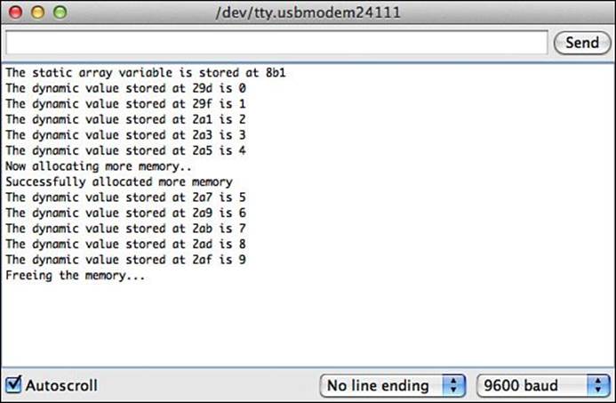
FIGURE 12.2 Using malloc and realloc to dynamically assign variables in memory.
The sketch also creates a standard static integer array variable called test and then displays the memory location where the Arduino stores it. This enables you to compare the locations where the Arduino stored the static and dynamic variables. Notice that the static variable’s memory location is higher in memory than the dynamic variable’s location. That’s because the static variable is stored in the stack data area, while the dynamic variable is stored in the heap data area.
The dynamic variable feature available in the heap can come in handy as you create your sketches. For example, if you’re not sure just how many data points you’ll retrieve from a sensor, you can dynamically alter your array to store them all on-the-fly.
Using Flash to Store Data
As you saw in Table 12.1, the SRAM memory area on the Arduino is somewhat limited in size. If you have to write large sketches that use lots of data, you may bump up against the memory limit and start getting memory collisions. To help solve this problem, you can free up some space in SRAM by utilizing the flash memory area to store some of the sketch data values.
While the flash memory area is primarily reserved for storing your sketch code, you can also use it to store static data values in your sketch. Because the flash memory area is only written to when you upload your sketch code, you can’t store any data that dynamically changes as your sketch runs, because the sketch code can’t overwrite the flash memory area itself.
This feature can come in handy for storing constant values required in your sketch, such as any text messages that you use for output. This section walks through the steps required to store and use data in the flash memory area.
Declaring the Flash Data Types
Storing your sketch data in the flash memory area requires using some special data types and functions built specially for the Arduino. Because these aren’t standard C programming features, you’ll have to load a special code library file into your sketch.
Hour 13, “Using Libraries,” discusses how to use external library files in your sketch, but basically, all you’ll need to do to load the Arduino flash library data types and functions is add this line to the start of your sketch:
#include <avr/pgmspace.h>
After you load the library, you can access the special data types and functions required to interface with flash memory. Table 12.2 shows the special data types that you must use for storing data in the flash memory area.
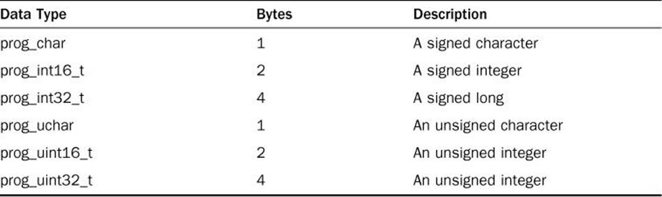
TABLE 12.2 Flash Memory Data Types
At the time of this writing, there isn’t a floating-point data type that you can use to store floating-point values in flash memory. You can only store integer and character values.
Also, to declare a variable that should be stored in flash memory, you must add the PROGMEM keyword to the variable declaration statement, like this:
prog_uint16_t maxTries PROGMEM = 10;
When you add the PROGMEM keyword to the variable declaration, it triggers the compiler to store the variable value in flash memory. Remember, after you do that, you cannot change the value assigned to the variable, it must remain constant.
Similarly, you can use this method to create constant a character array string value in your sketches:
prog_uchar message1[] PROGMEM = "This is a test message";
This can really come in handy if your sketch must store a lot of text messages for output. By placing the string values in flash memory, you free up extra space in the SRAM memory heap data area.
The second part of the process is accessing the data that you store in the flash memory area. Unfortunately, that’s not as straightforward as just referencing the variables. The next section shows how to do that.
Retrieving Data from Flash
The downside to storing data in flash memory is that you can’t access the data directly using the standard C functions. Because the flash memory is a separate memory space, they require special functions to access them. The pgmspace.h library provided by AVR includes several functions that allow us to access data stored in the Flash memory area, shown in Table 12.3.
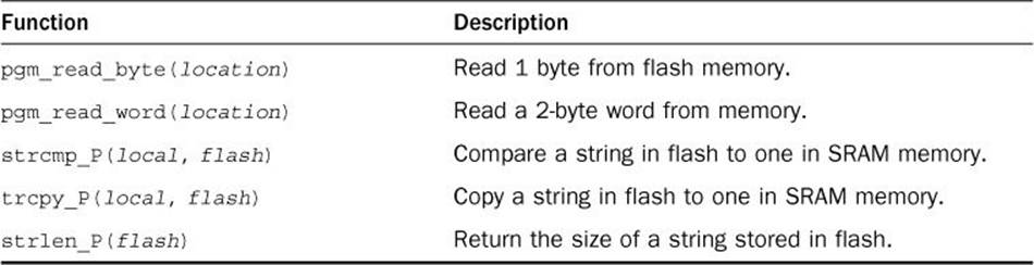
TABLE 12.3 Functions to Access Flash Memory
The most common way to handle strings stored in flash is to copy them into a variable stored in SRAM memory when you need to use them. That way you can store all of the strings in flash, and only one variable in SRAM memory to use as a buffer, like this:
prog_char message1[] PROGMEM = "This is a test string";
char buffer[50];
strcpy_P(buffer, message1);
You can also get fancy by creating a table of the string pointers in flash memory:
prog_char *table[] PROGMEM = {message1, message2, message3};
You can then use the pgm_read_word function to read the appropriate pointer to access the strings stored in flash memory:
strcpy_P(buffer, (char *)pgm_read_word(&(table[0])));
Let’s go through an example of how to do just that.
Testing It Out
Now that you’ve seen the individual pieces required to store and retrieve data in the flash memory area, let’s walk through an example that demonstrates how to do that.
![]() Try It Yourself: Storing Strings in Flash Memory
Try It Yourself: Storing Strings in Flash Memory
In this example, you store a series of string values in flash memory so that they don’t take up space in the SRAM memory area and then create a table of pointers that your sketch code uses to access the strings as needed. Here are the steps to create and run the demo sketch:
1. Open the Arduino IDE, and enter this code into the editor window:
#include <avr/pgmspace.h>
prog_char message1[] PROGMEM = "This is a short message";
prog_char message2[] PROGMEM = "This is a little longer message";
prog_char message3[] PROGMEM = "Test message 3";
prog_char message4[] PROGMEM = "This is the last message in the test";
prog_char *table[] PROGMEM = {message1, message2, message3, message4};
void setup() {
Serial.begin(9600);
char buffer[50];
int size;
for(int i = 0; i < 4; i++) {
size = strlen_P((char *)pgm_read_word(&(table[i])));
strcpy_P(buffer, (char *)pgm_read_word(&(table[i])));
Serial.print("The size of the string is: ");
Serial.print(size);
Serial.print(": ");
Serial.println(buffer);
}
}
void loop() {
}
2. Save the sketch code as sketch1202.
3. Click the Upload icon to verify, compile, and upload the sketch to your Arduino unit.
4. Open the serial monitor to run the sketch and view the output.
The strings are defined as character arrays, except that they use the prog_char data type. The table also uses the prog_char pointer type and contains the pointers to each of the strings stored in the flash memory. The code uses the special strlen_P and strcpy_P functions to access the strings in flash memory, using the pgm_read_word function to read the pointer address to use for the reference. Figure 12.3 shows the output that you should see in the serial monitor window.
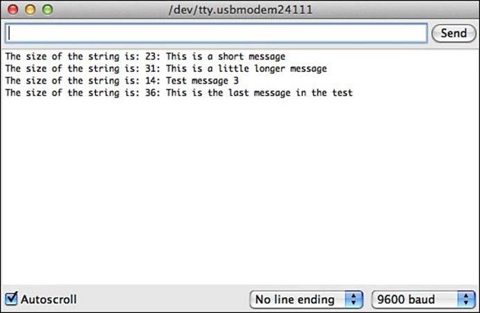
FIGURE 12.3 Storing strings in flash memory and retrieving them.
By using this method, you can store as many strings as you need in flash memory (or at least until you run out of flash memory), saving space in SRAM memory for your program variables.
Using the EEPROM Memory
The last trick to help with memory management in the Arduino is the EEPROM memory. With EEPROM memory, you can not only store and retrieve data outside of the SRAM memory area, but you can also do that in different runs of the sketch code. The EEPROM memory retains the data after a reboot of the Arduino (even after you power down the Arduino and restart it), making it ideal for storing values that your sketches need to “remember” from one run to another.
Watch Out: Writing to EEPROM
A limitation applies to the EEPROM memory. Just like the flash memory, it becomes unreliable after about 100,000 writes. You won’t receive any error messages when the write data, it just may not complete properly. Keep this in mind when writing to your EEPROM memory area.
The following sections show how to use the Arduino EEPROM library to read and write data to the EEPROM memory area.
Using the EEPROM Library
To use the EEPROM memory area, you must use special functions. Just as with the code to access the flash memory area, you’ll first need to include a library file in your sketch to use the EEPROM functions. The EEPROM library is part of the Arduino IDE standard package, so you can include the library file in your sketch by clicking Sketch > Import Library > EEPROM from the menu bar. This automatically adds the #include line to your sketch:
#include <EEPROM.h>
After you include the standard EEPROM library file, you can use the two standard EEPROM functions in your code:
![]() read(address)—to read the data value stored at the EEPROM location specified by address.
read(address)—to read the data value stored at the EEPROM location specified by address.
![]() write(address,value)—to read values to the EEPROM location specified by address.
write(address,value)—to read values to the EEPROM location specified by address.
Each address value starts at 0 for the start of the EEPROM memory area, and increases until the end of the EEPROM memory area. Depending on the Arduino unit you have, the end value will be different. The Arduino Uno unit contains 1KB of EEPROM memory. Because 1KB is actually 1024 bytes, the largest memory area you can write to on the Uno is 1023. (EEPROM memory starts at address 0.)
Watch Out: Memory Address Wrap
Unfortunately, the Arduino will allow you to write to a memory address larger than the amount of EEPROM memory on your Arduino unit. If the address value is larger, the Arduino wraps around in memory. So, if you have an Arduino Uno unit and write to memory address 1024, the data value is stored in address 0. Be careful when specifying the address values in your sketches!
Unfortunately, there are no automated ways to handle data stored in the EEPROM; you must keep track of all data you store in the EEPROM manually. It can help to draw up a memory map that diagrams what values you store where in the EEPROM memory area.
Experimenting with the EEPROM Library
Let’s go through an example that stores values in EEPROM and then reads them back. First, we’ll create a sketch that stores the values in the EEPROM memory area. Follow these steps:
1. Open the Arduino IDE, and select Sketch > Import Library > EEPROM.
2. Enter this code into the editor window under the #include <EEPROM.h> directive that was added by the library import:
#include <EEPROM.h>
void setup() {
Serial.begin(9600);
Serial.println("Storing data in EEPROM...");
int test[] = {10, 20, 30, 40, 50};
int i;
for(i = 0; i < 5; i++) {
EEPROM.write(i, test[i]);
}
Serial.println("Data written to EEPROM");
}
void loop() {
}
3. Save the sketch code as sketch1203.
4. Click the Upload icon to verify, compile, and upload the sketch code to your Arduino unit.
5. Open the serial monitor to run the sketch code and view the output.
The sketch1203 code uses the write function from the EEPROM library to store the array values in the first five spaces in EEPROM memory. You should see the output shown in Figure 12.4 in the serial monitor.
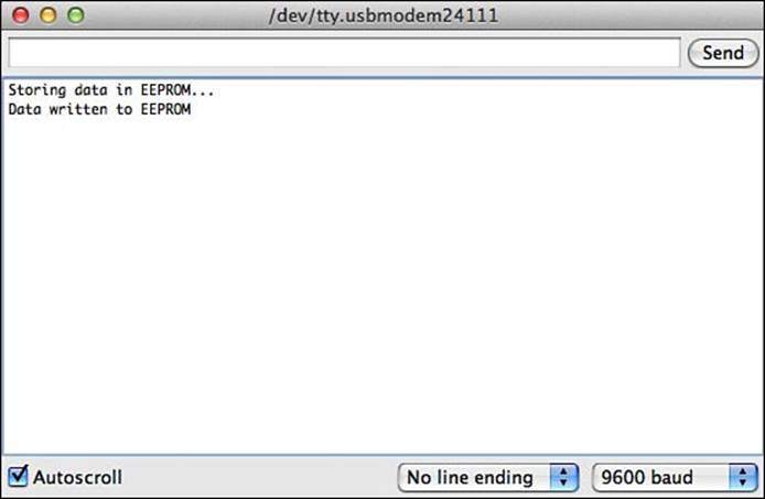
FIGURE 12.4 Storing integer values in EEPROM memory.
The next set of steps creates a second sketch to read the values that you stored in the EEPROM memory:
1. Open the Arduino IDE and select Sketch > Import Library > EEPROM.
2. Enter this code into the editor window under the #include directive that was added by the library import:
#include <EEPROM.h>
void setup() {
Serial.begin(9600);
int test2[5];
int i;
Serial.println("Reading data from EEPROM...");
for(i = 0; i < 5; i++) {
test2[i] = EEPROM.read(i);
Serial.println(test2[i]);
}
}
void loop() {
}
3. Save the sketch code as sketch1204.
4. Click the Upload icon to verify, compile, and upload the sketch code to your Arduino unit.
5. Open the serial monitor to run the sketch and view the output.
6. Disconnect your Arduino unit so that it loses power; then reconnect it back to your workstation.
7. Open the serial monitor again to run the sketch and view the output.
The output from the sketch1204 code should display the five data values that you stored from the sketch1203 code (as shown in Figure 12.5), even after removing power to the Arduino.
FIGURE 12.5 Retrieving data from the EEPROM memory area.
By The Way: Storing More Complicated Data Structures
Because the EEPROM read and write functions can retrieve only 1 byte of data, they’re somewhat limited in what they can store (only values from 0 to 255). However, some enterprising Arduino users have created a library of functions that allow you to easily store other data types, including character arrays and data structures, using special functions. This library is called the EEPROM Extended library, or EEPROMex for short. Unfortunately, it’s not included as part of the standard Arduino IDE package, so you have to download and install it separately. You’ll learn about how to do that in the next hour.
Summary
This hour focused on alternative ways to store data in your Arduino sketches. First, it showed just how the Arduino uses the SRAM memory area to store the variables that you declare in your sketches. After that, it showed how you can use the heap data area in SRAM to create and use dynamic variables that can change in size as your sketch runs. Next, it walked through how to store static values in flash memory to help free up space in SRAM. You must use special data types and functions to store data in the flash memory area with the program code. Finally, the hour discussed how to use the EEPROM memory that is built in to the Arduino CPU itself. You can use the standard EEPROM library to read and write individual bytes of data in EEPROM. This data remains intact even after the power is removed from the Arduino unit.
The next hour covers how to work with the different libraries available for the Arduino and how to create your own library of functions that you can share with others.
Workshop
Quiz
1. Where can you create dynamic variables that can change in size as you run your Arduino sketches?
A. The SRAM stack data area
B. The flash memory area
C. The SRAM heap data area
D. The EEPROM memory area
2. Data values stored in flash are lost when power is removed from the Arduino. True or false?
3. How do you retrieve a value stored in the EEPROM memory area?
Answers
1. C. You can create dynamic variables using the malloc or calloc functions in the SRAM heap data area.
2. False. The flash memory area retains the program and data information stored there after power is removed. When power is restored to the Arduino, the program runs, and the data values you stored in flash will also still be there.
3. You must use the EEPROM.read function available in the EEPROM library for the Arduino. You cannot use a standard C function to read or write data to the EEPROM memory area.
Q&A
Q. If the EEPROM memory area on my Arduino already contains data stored in it, can I read the data?
A. Yes, but you might not be able to make any sense out of it! You can read the data stored in the EEPROM 1 byte at a time, but you’d have to determine if the data stored was a character, number, or data structure. That could be close to impossible to figure out if you weren’t the one who stored the data.
Q. Should I erase the EEPROM memory area by placing 0s (zeros) in all the memory locations when I’m done using it?
A. It depends on the sensitivity of your data. Remember, the more you write the EEPROM memory, the fewer times you have before it becomes unreliable. If there isn’t a requirement to erase data from the EEPROM, I wouldn’t bother doing it. You can overwrite old data with new data at any time.
All materials on the site are licensed Creative Commons Attribution-Sharealike 3.0 Unported CC BY-SA 3.0 & GNU Free Documentation License (GFDL)
If you are the copyright holder of any material contained on our site and intend to remove it, please contact our site administrator for approval.
© 2016-2026 All site design rights belong to S.Y.A.