Sams Teach Yourself Arduino Programming in 24 Hours (2015)
Part III: Arduino Applications
HOUR 14 Working with Digital Interfaces
HOUR 15 Interfacing with Analog Devices
HOUR 16 Adding Interrupts
HOUR 17 Communicating with Devices
HOUR 18 Using Sensors
HOUR 19 Working with Motors
HOUR 20 Using an LCD
HOUR 21 Working with the Ethernet Shield
HOUR 22 Advanced Network Programming
HOUR 23 Handling Files
HOUR 24 Prototyping Projects
Hour 14. Working with Digital Interfaces
What You’ll Learn in This Hour:
![]() How the Arduino handles digital signals
How the Arduino handles digital signals
![]() How to output a digital signal from a sketch
How to output a digital signal from a sketch
![]() How to read a digital signal in a sketch
How to read a digital signal in a sketch
![]() Different ways to detect digital inputs
Different ways to detect digital inputs
Now that you’ve seen the basics of the Arduino programming language, it’s time to start digging into the code to interface with the Arduino hardware. In this hour, you learn how to work with the digital interfaces on the Arduino, both reading digital data from external devices and sending digital signals out to them.
Digital Overview
The primary purpose of the Arduino is to control external devices. The Arduino provides two types of interfaces to do that:
![]() Analog interfaces for reading analog voltages
Analog interfaces for reading analog voltages
![]() Digital interfaces for reading and writing digital signals
Digital interfaces for reading and writing digital signals
This hour discusses the digital interfaces and focuses on the basics of how to read digital signals sent to the interface from an external device and how to write a digital signal to send to a device connected to an interface. In later hours, you’ll see how to use those features to interact with specific sensors or other digital devices.
Each of the Arduino models provides a number of digital interfaces. Table 14.1 shows the number of digital interfaces available on each Arduino model.
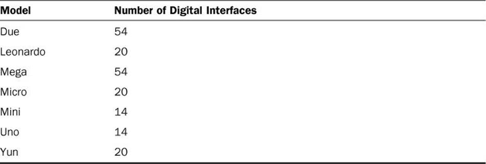
TABLE 14.1 Arduino Digital Interfaces by Model
You can use each of the digital interfaces on the Arduino for either input or output. A few of the digital interfaces can also be used for other purposes (such as generating a pulse-width modulation signal or communicating with serial ports); later hours cover those topics. For now, let’s just take a closer look at how to use the digital interfaces to interact with digital signals.
The Digital Interface Layout
The standard header layout in the Arduino footprint (see Hour 1, “Introduction to the Arduino”) provides 14 digital interfaces along the top header block of the device, as shown in Figure 14.1.
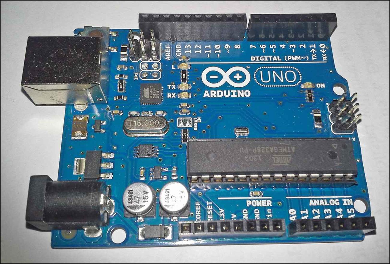
FIGURE 14.1 Digital interfaces on the Arduino Uno.
The digital interfaces are labeled 0 through 13. This is the standard header layout available on all Arduino devices. For the Uno and Mini devices, those are the only digital interfaces available. For the Leonardo, Micro, and Yun models, the six analog interfaces, labeled A0 through A5, also double as digital interfaces 14 through 20.
For the Due and Mega models, a separate dual-row header block is included along the right side of the unit. The dual-row header block contains digital interfaces 21 through 53.
Setting Input or Output Modes
You can use each digital interface on the Arduino as either an input or an output, but not both at the same time. To tell the Arduino which mode your sketch uses for a specific digital interface, you must use the pinMode function:
pinMode(pin, MODE);
The pinMode function requires two parameters. The pin parameter determines the digital interface number to set. The MODE parameter determines whether the pin operates in input or output mode. There are actually three values you can use for the interface mode setting:
![]() INPUT—To set an interface for normal input mode.
INPUT—To set an interface for normal input mode.
![]() INPUT_PULLUP—To set an interface for input mode, but use an internal pullup resistor.
INPUT_PULLUP—To set an interface for input mode, but use an internal pullup resistor.
![]() OUTPUT—To set an interface for output mode.
OUTPUT—To set an interface for output mode.
The INPUT_PULLUP mode may be a bit confusing. Each Arduino model provides an option to activate an internal pullup resistor on each individual digital interface. The INPUT_PULLUP mode value determines whether the internal pullup resistor is activated on the digital interface or not. You’ll learn more about that later on in this hour.
After you set the mode for the digital interface, you’re ready to start using it. The next section discusses how to use the digital interfaces as outputs in your sketches.
Using Digital Outputs
For the output mode, your sketch can set the voltage level on each individual digital interface to either a logic HIGH or LOW value. You do that using the digitalWrite function:
digitalWrite(pin, value);
The pin parameter value specifies the digital interface number to send the output to. The value parameter specifies the HIGH or LOW setting to determine the output voltage. For example:
digitalWrite(10, HIGH);
The HIGH value sends a +5 volt signal to the digital output on interface 10. The Arduino generates digital signals using 40mA of current. For lower current devices, such as LEDs, you must place a resistor (typically around 1K ohms) in the circuit with the LED to help limit the current applied to the LED.
For high-current devices, such as motors and relays, you need to connect either a relay or a transistor to the digital output to use as a switch to control the high-current circuit. The transistor isolates the high-current circuit from the Arduino digital interface. When the digital interface is at aHIGH voltage level, the transistor conducts, allowing the higher-current circuit to flow. When the interface is at a LOW voltage level, the transistor blocks, breaking the higher-current circuit. Figure 14.2 demonstrates these configurations.
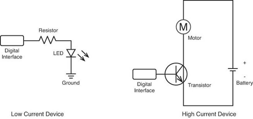
FIGURE 14.2 Connecting high- and low-current devices to the digital interface.
When connected directly to an electronic circuit, the digital interface on the Arduino can act as either a current source or as a current sink. When acting as a current source, the digital interface outputs a current when set to the HIGH voltage value. The electronic components connected to the Arduino interface must complete the circuit by providing a ground voltage (0 volts).
When acting as a current sink, the digital interface outputs a LOW voltage value of 0 volts, emulating a ground connection. In this case, the electronic circuit must provide current from a voltage source of +5 volts to complete the circuit. Figure 14.3 demonstrates both of these modes.
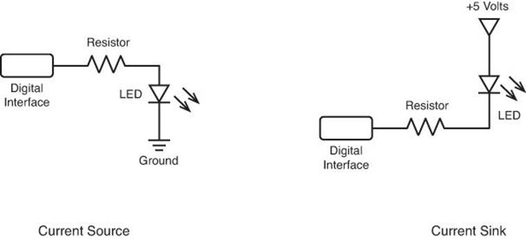
FIGURE 14.3 The Arduino digital interface as a current source or current sink.
The next section demonstrates creating a sketch to show how to use the digital output features.
Experimenting with Digital Output
Now that you’ve seen the basics of how to generate and control a digital signal from your Arduino, let’s go through an example of using that feature with a real electronic circuit.
For this example, you need a few electronic components:
![]() Three LEDs (preferably red, yellow, and green, but they can be the same color if that’s all you have available). Many Arduino starter kits come with a few 5mm, 30mA LEDs, and these will work just fine.
Three LEDs (preferably red, yellow, and green, but they can be the same color if that’s all you have available). Many Arduino starter kits come with a few 5mm, 30mA LEDs, and these will work just fine.
![]() Three 1K ohm resistors (color code brown, black, red).
Three 1K ohm resistors (color code brown, black, red).
![]() A breadboard.
A breadboard.
![]() Four jumper wires.
Four jumper wires.
The resistors are for limiting the current that goes through the LEDs. The Arduino can output 40mA of current, so if you use a 30mA LED, you’ll need to place at least a 1K ohm resistor in series with each LED so it doesn’t burn out. You can use a larger resistor if you like; the LED will just be a little dimmer.
After you gather these components, you can start the example.
![]() Try It Yourself: Digital Traffic Signal
Try It Yourself: Digital Traffic Signal
For this example, you create a traffic signal that your Arduino will control using three separate digital interfaces. This project requires building a circuit, along with coding a sketch. First, follow these steps to build the electronic circuit:
1. Place the three LEDs on the breadboard so that the short leads are all on the same side and that the two leads straddle the space in the middle of the board so that they’re not connected. Place them so that the red LED is at the top, the yellow LED in the middle, and the green LED is at the bottom of the row.
2. Connect a 1K ohm resistor between the short lead on each LED to a common rail area on the breadboard.
3. Connect a jumper wire from the common rail area on the breadboard to the GND interface on the Arduino.
4. Connect a jumper wire from the green LED long lead to digital interface 10 on the Arduino.
5. Connect a jumper wire from the yellow LED long lead to digital interface 11 on the Arduino.
6. Connect a jumper wire from the red LED long lead to digital interface 12 on the Arduino.
That completes the hardware circuit. Figure 14.4 shows the circuit diagram for what you just created.
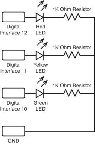
FIGURE 14.4 The circuit diagram for the traffic signal example.
Now you’re ready to start coding the sketch that controls the traffic signal circuit. Just follow these steps:
1. Open the Arduino IDE on your workstation and enter this code into the editor window:
int stop = 6;
int yield = 2;
int go = 6;
void setup() {
Serial.begin(9600);
pinMode(10, OUTPUT);
pinMode(11, OUTPUT);
pinMode(12, OUTPUT);
digitalWrite(10, LOW);
digitalWrite(11, LOW);
digitalWrite(12, LOW);
}
void loop() {
stoplight(stop);
golight(go);
yieldlight(yield);
}
void stoplight(int time) {
digitalWrite(10, LOW);
digitalWrite(11, LOW);
digitalWrite(12, HIGH);
Serial.println("Light mode: Stop");
delay(time * 1000);
}
void yieldlight(int time) {
digitalWrite(10, LOW);
digitalWrite(11, HIGH);
digitalWrite(12, LOW);
Serial.println("Light mode: Yield");
delay(time * 1000);
}
void golight(int time) {
digitalWrite(10, HIGH);
digitalWrite(11, LOW);
digitalWrite(12, LOW);
Serial.print("Light mode: Go - ");
Serial.println(time);
delay(time * 1000);
}
2. Save the sketch as sketch1401.
3. Click the Upload icon to verify, compile, and upload the sketch code to your Arduino unit.
4. Open the serial monitor to start the sketch and to view the output from the sketch.
The setup function defines the pin modes for the three digital interfaces and sets their default values to LOW. This causes all the LEDs to remain off, because the LED circuits require a HIGH signal voltage for power.
Each state of the traffic signal (stop, go, and yield) is a separate function. Each function defines the power required to each LED for that state. (For example, in stop mode, interface 12 is set to HIGH to power the red LED, while interfaces 10 and 11 are set to LOW to turn off the yellow and green LEDs.) Also in each function is a delay function to pause the traffic light at that state for a predetermined amount of time, set by the value passed to the function. The global variables stop, go, and yield contain the number of seconds for each state.
When you run the sketch, the LEDs should light up simulating a U.S.-style traffic signal, and you should see an output log in the serial monitor window indicating which function is running at any given time.
By The Way: Troubleshooting Interfaces
Using the serial monitor output is a great tool to help you troubleshoot digital interfaces. It helps you see inside the sketch to know when things should be happening. Once you get the traffic signal sketch working, you can remove the Serial.println function lines so that there isn’t any logging output.
Working with Digital Inputs
For input mode, the digital interface detects a digital voltage provided by the external electronic device using the digitalRead function:
result = digitalRead(pin);
The pin parameter determines which digital interface to read. The digitalRead function returns a Boolean HIGH or LOW value based on the input signal, which you can compare to a 1 or 0 integer value in your code.
The digital interface can only detect binary digital signals, either a true value, or a false value. For the Arduino to detect a true value, the input voltage must be between +3 and +5 volts on the digital interface. For a false value, the Arduino must detect a voltage between 0 and +2 volts.
Watch Out!: Undetermined Values
Notice that this range leaves an area between +2 and +3 volts that is not assigned to a Boolean value. Any voltage detected by the digital interface within that range will produce an unreliable result.
The following sections cover a couple of issues you need to be aware of when using the digital interfaces as inputs.
Input Flapping
An issue often overlooked by novice Arduino users is input flapping. Input flapping occurs when a digital interface is not specifically connected to a source voltage (either +5 volts or ground). Figure 14.5 shows a circuit diagram that demonstrates this problem.
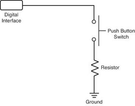
FIGURE 14.5 An Arduino interface that will experience input flapping.
When the switch in Figure 14.5 is depressed, the digital interface is connected to the ground voltage, which sets the input to a LOW value. However, when the switch is released, the digital interface is not connected to anything. When this happens, the digitalRead function returns an inconsistent value, often dependent on any ambient voltage that may be present on the interface. There’s no guarantee that the input will return a HIGH value.
To prevent input flapping, you should always apply some signal to the digital interface at all times. You can do so in two ways:
![]() Connect the interface to +5 volts, called a pullup
Connect the interface to +5 volts, called a pullup
![]() Connect the interface to ground, called a pulldown
Connect the interface to ground, called a pulldown
In the pullup circuit, when the switch is open, the digitalRead function returns a HIGH value, and when the switch is depressed, it returns a LOW value. The pulldown circuit operates in the opposite way; when you depress the switch, the interface receives a HIGH value, but is at a LOWvalue otherwise. Figure 14.6 demonstrates this process.
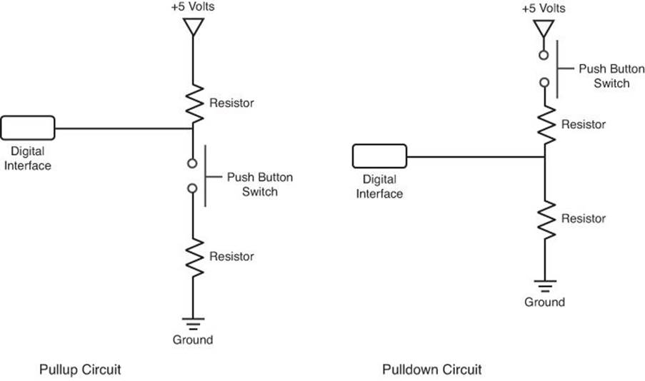
FIGURE 14.6 Using pullup and pulldown circuits on a digital interface.
Setting a pullup or pulldown circuit requires a little extra work on your part. Fortunately, another method enables you to accomplish that.
Using the Internal Pullup
Because of the importance of using a pullup or pulldown circuit, the Arduino developers provide an internal pullup circuit for each digital interface. You can activate the internal pullup circuit by using the INPUT_PULLUP label in the pinMode function:
pinMode(8, INPUT_PULLUP);
The INPUT_PULLUP label activates an internal pullup resistor on the specified digital interface, setting the default value to HIGH for the interface. The external circuit connected to the digital interface must connect the interface to ground to change the input voltage.
By using the internal pullup circuit, you don’t need to create the external pullup circuit, thus reducing the amount of hardware you need for your projects.
Using Interface 13 as an Input
Digital interface 13 is somewhat special on all Arduino units. It has a resistor and LED connected to it at all times, allowing you to easily monitor output from that digital interface directly on the Arduino board. This comes in handy if you’re trying to quickly troubleshoot a digital setting without having to connect external hardware.
The downside to this is that the LED and resistor are always connected to the interface. If you use interface 13 for input, any voltage applied to the interface will interact with the internal resistance applied to the input circuit. This means that the undetermined area between +2 and +3 volts becomes somewhat larger for that digital interface. To be safe, make sure to always apply a full +5 volts for a HIGH signal when using interface 13 for input.
Experimenting with Digital Input
Now that you’ve seen the basics of how to use digital interfaces for input, let’s go through an example to demonstrate how that works. In this example, you add on to the traffic signal example you created earlier in this hour. You need three more components:
![]() A momentary contact switch
A momentary contact switch
![]() A 10K ohm resistor (color code brown, black, orange)
A 10K ohm resistor (color code brown, black, orange)
![]() One jumper wire
One jumper wire
The momentary contact switch is normally in an open state. When you press the button, the switch makes contact and is in a closed state, connecting the two pins of the switch to complete a circuit. When you release the button, the switch goes back to the open state.
The Arduino Starter Kit provides small momentary contact switches that you can plug directly into the breadboard. These work great for our breadboard examples. You can also purchase similar switches from most electronic parts suppliers, such as Adafruit or Newark Electronics.
![]() Try It Yourself: Using a Digital Input
Try It Yourself: Using a Digital Input
In this example, you add a switch to your traffic signal circuit. When the switch is held closed, the traffic signal code increases the amount of time allotted for the green LED state. First, the steps you need to build the circuit:
1. Place the momentary contact switch on the breadboard under the existing LEDs so that the switch straddles the center divide of the breadboard.
2. Connect the 10K ohm resistor so that one lead connects to one pin of the momentary contact switch and the other lead connects to the breadboard rail connected to the Arduino GND interface.
3. Connect the jumper wire from digital interface 8 on the Arduino to the other pin of the momentary contact switch.
That’s all you need to add for the hardware. Now, for the code changes, follow these steps:
1. Open the Arduino IDE.
2. Select File from the menu bar, and then select the sketch1401 code to open.
3. Add the checkSwitch function to the bottom of the existing sketch code:
int checkSwitch() {
int set = digitalRead(8);
Serial.print("checking switch...");
if (set) {
Serial.println("the switch is open");
return 6;
} else {
Serial.println("the switch is closed");
return 10;
}
}
4. Modify the setup function to add a statement to set the interface mode for interface 8 to INPUT_PULLUP:
pinMode(8, INPUT_PULLUP);
5. Modify the loop function code to add a call to the checkSwitch function at the end of the loop, and assign the output to the go variable. Here’s what the final loop function code should look like:
void loop() {
stoplight(stop);
golight(go);
yieldlight(yield);
go = checkSwitch();
}
6. Save the sketch code as sketch1402.
7. Click the Upload icon to verify, compile, and upload the sketch code to your Arduino unit.
8. Open the serial monitor to run the sketch and view the output.
The sketch1402 code uses the INPUT_PULLUP mode for interface 8 so that when the switch is not pressed, the input value will be set to HIGH. When you press the switch, the input will be set to LOW, as the switch connects the interface to the ground using the 10K ohm resistor. (The resistor helps prevent short-circuiting the digital interface if something goes wrong.) The checkSwitch function returns a different value based on whether the switch is pressed.
When you run the sketch, the default value for the go variable of 6 remains for as long as the switch is not pressed when the checkSwitch function runs. When you press and hold the switch while the checkSwitch function runs, the value for the go variable changes to 10.
The trick is to depress the switch while the checkSwitch function is running. To do that, just hold down the switch while the yellow LED is lit, and then release it when the red LED lights. When you do that, the next iteration of the green LED will be longer.
The output in the serial monitor will show the setting of the go variable in each loop iteration, as shown in Figure 14.7.
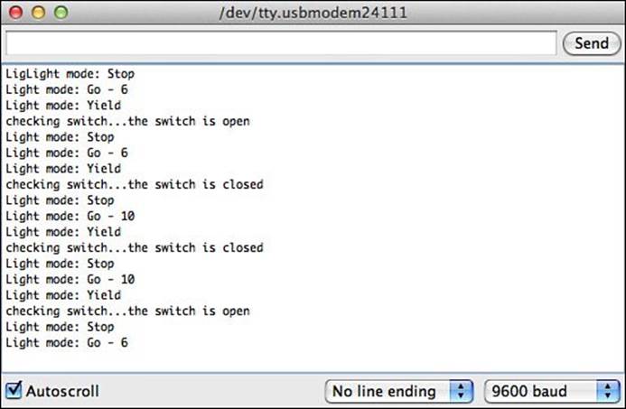
FIGURE 14.7 Output from controlling the traffic light using the switch.
When the switch is open, the green LED stays on for 6 seconds, but when you close the switch during the yellow LED time, the next iteration of the green LED stays on for 10 seconds.
Summary
This hour explored how to use the digital interfaces available on the Arduino. The Arduino provides multiple interfaces for detecting input digital signals, and also for generating output digital signals.
You must use the pinMode function to set the digital interface for input or output mode. For output signals, you use the digitalWrite function to generate a 40mA +5 volt output signal, which can power low-current devices. You can connect a transistor to the digital output to control higher-current devices.
For detecting digital input signals, you use the digitalRead function. You should always set a default value for the interface using either a pullup or pulldown voltage. You can do that either internally using the INPUT_PULLUP label in the pinMode function or externally by using the electronic circuit. This prevents input flapping, which will result in indeterminate values.
The next hour covers how to use the analog interfaces available on the Arduino. They enable you to both detect analog voltages for input and even to generate analog signals that you can use to control analog circuits, such as motors.
Workshop
Quiz
1. Which function do you use to activate the internal pullup resistor on a digital interface?
A. digitalRead
B. digitalWrite
C. pinMode
D. analogRead
2. If no voltage is applied to the digital interface, the digitalRead function will return a HIGH value. True or false?
3. What command should you use to set digital interface 3 to be used for input mode and to activate the internal pullup resistor?
Answers
1. C. The pinMode function allows you to use the INPUT_PULLUP mode to enable the internal pullup resistor on the specified digital interface.
2. False. If no input voltage is applied to the digital interface, the interface may flap between a HIGH and LOW value. You should always set an input interface to a specific voltage, either HIGH or LOW, at all times in your circuits.
3. pinMode(3, INPUT_PULLUP);
Q&A
Q. What happens if a voltage change occurs on the digital input interface while the sketch is doing something else and not running the digitalRead function?
A. The digitalRead function can only return the current value set on the digital interface at the time your sketch runs it. It can’t detect whether a voltage change occurs between the times you run the command.
Q. How can I detect whether a change occurs between when the sketch runs the digitalRead function?
A. You can use interrupts to detect any changes on a digital interface. Those are discussed in Hour 16, “Adding Interrupts.”
All materials on the site are licensed Creative Commons Attribution-Sharealike 3.0 Unported CC BY-SA 3.0 & GNU Free Documentation License (GFDL)
If you are the copyright holder of any material contained on our site and intend to remove it, please contact our site administrator for approval.
© 2016-2026 All site design rights belong to S.Y.A.