Sams Teach Yourself Arduino Programming in 24 Hours (2015)
Part III: Arduino Applications
Hour 15. Interfacing with Analog Devices
What You’ll Learn in This Hour:
![]() How the Arduino handles analog signals
How the Arduino handles analog signals
![]() How to read an analog signal
How to read an analog signal
![]() How to output an analog signal
How to output an analog signal
![]() Different ways to detect analog inputs
Different ways to detect analog inputs
Besides working with digital devices, the Arduino can also interface with analog devices. However, working with analog signals can be a bit tricky because the digital Arduino must convert between the analog signal and digital values. Fortunately, the Arduino developers have made things easier for us by providing a group of simple functions to use. In this hour, you learn how to work with the Arduino analog functions to read analog signals from the analog input interfaces on the Arduino and how to generate analog output signals using the digital interfaces.
Analog Overview
Although microcontrollers are built around digital computers, often you’ll find yourself having to interface with analog devices, such as controlling motors that require an analog input voltage or reading sensors that output an analog signal. Because of that, the Arduino developers decided to add some analog features to the Arduino microcontroller.
Working with analog signals requires some type of converter to change the analog signals into digital values that the microcontroller can work with, or changing digital values produced by the microcontroller into analog voltages that the analog devices can use. The next sections discuss how the Arduino handles analog input and output signals.
Detecting Analog Input Signals
For working with analog input signals, the Arduino includes an analog-to-digital converter (ADC). The ADC converts an analog input signal into a digital value. The digital value is scaled based on the value of the analog signal. Your Arduino sketch can read the digital value produced by the converter and use it to determine the value of the original analog signal.
Each of the Arduino units includes an ADC for sensing analog input voltages and converting them into digital values. Different Arduino models use different types and sizes of ADC converters. Table 15.1 shows the number of analog interfaces each Arduino model supports.
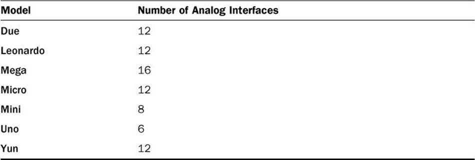
TABLE 15.1 Arduino Analog Interfaces by Model
The ADC converts the analog input voltage present on the interface to a digital value based on a preset algorithm. The range of digital values produced by the algorithm depends on the bits of resolution that the ADC uses.
For most Arduino models, the ADC uses a 10-bit resolution to produce the digital value. Thus, the digital values range from 0 for an input of 0 volts, to 1023, for an input of +5 volts. However, the Leonardo uses a 12-bit resolution ADC, which makes the upper value 4023 for +5 volts. This provides for a more granular result as the voltages change, allowing your sketch to detect smaller voltage changes on the input interface.
Generating Analog Output Signals
For generating analog signals for output, the converter is called a digital-to-analog converter (DAC). A DAC receives a digital value from the microcontroller and converts it to an analog voltage that is used to provide power to an analog device or circuit. The value of the analog voltage is determined by the digital value sent to the DAC; the larger the digital value, the larger the analog output voltage.
However, DAC devices are somewhat complicated and require extra circuitry to implement. Because of this, only one Arduino model, the Leonardo, includes an actual DAC to output true analog signals. If you own one of the other Arduino models, don’t fret; there’s another method for generating analog output signals.
Pulse-width modulation (PWM) simulates an analog output signal using a digital signal. It does that by controlling the amount of time a digital output toggles between the HIGH and LOW values. This is called the signal duty cycle.
The length of the signal duty cycle determines the simulated analog voltage generated by the digital interface. The longer the duty cycle, the higher the analog voltage that it simulates. A duty cycle of 100% means that the digital output is always at the HIGH value, which generates an output voltage of +5 volts. A signal duty cycle of 0% means that the digital output is always at the LOW value, which generates an output voltage of 0 volts.
For values in between, the digital output toggles between the HIGH and LOW values to produce a simulated analog signal. For example, when the duty cycle is 50%, the HIGH value is applied half of the time, which simulates an analog voltage of +2.5 volts. If the duty cycle is 75%, the HIGHvalue is applied three-fourths of the time, which simulates an analog voltage of +3.75 volts. Your sketch can use the duty cycle to simulate any analog voltage level from 0 volts to +5 volts on the Arduino.
Locating the Analog Interfaces
The standard header layout in the Arduino footprint (see Hour 1, “Introduction to the Arduino”) provides six analog input interfaces along the bottom header block of the device, as shown in Figure 15.1.
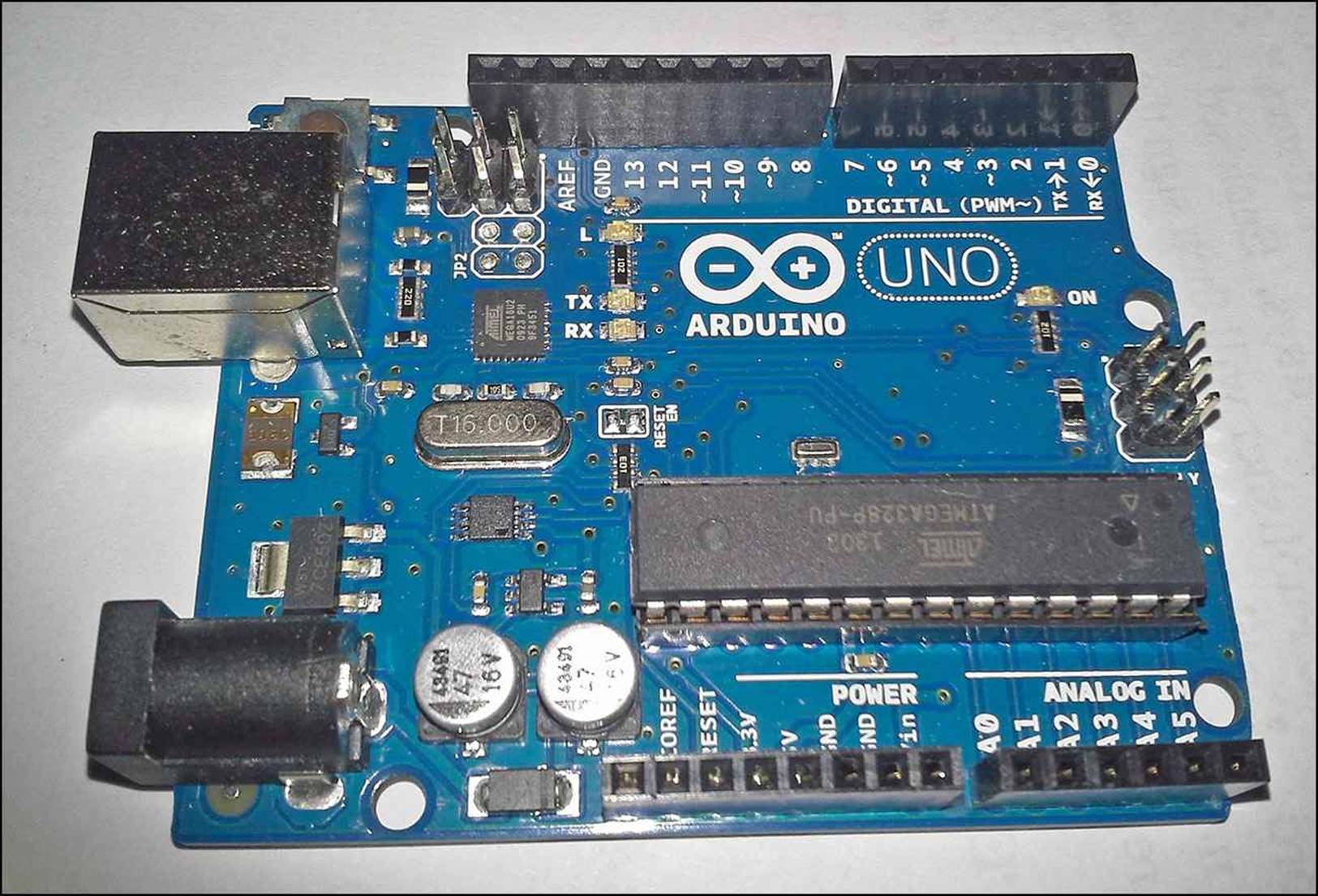
FIGURE 15.1 Analog interfaces on the Arduino Uno.
The analog input interfaces on the Arduino are labeled A0 through A5. For the Uno and Mini devices, those are the only analog input interfaces available. For the Leonardo, Micro, and Yun devices, the additional analog interfaces are found on digital interfaces 4, 6, 8, 9, 10, and 12.
The Arduino only supports PWM output on a subset of the digital interfaces. For the Arduino Uno, digital interfaces 3, 5, 6, 9, 10, and 11 support PWM. You can tell which digital interfaces on your specific Arduino unit support PWM by the labeling on the unit. The PWM digital interfaces are marked on the Arduino using a tilde (~) before the digital interface number (see Figure 15.1).
Working with Analog Input
The main function that you use to work with the Arduino analog input interfaces is the analogRead function. It returns an integer value from the specified ADC interface, which represents the analog voltage applied to the interface:
int input;
input = analogRead(A0);
The analog interfaces use the A prefix to indicate the interface (A0 through A5 on the Uno). For most Arduino models, the analogRead function returns a digital value from 0 to 1023. For the Leonardo, the digital value is from 0 to 4023.
Let’s go through an example to test the analog input on your Arduino unit.
![]() Try It Yourself: Detecting Analog input
Try It Yourself: Detecting Analog input
In this example, you build a simple analog circuit that uses a potentiometer to change the input voltage on the Arduino analog input.
A potentiometer is a variable resistor that you control rotating a control arm. As you rotate the control arm, it changes the resistance between the pins of the potentiometer. The potentiometer has three pins. The two outer pins connect across the entire resistor in the potentiometer, providing a constant resistance value. The inner pin acts as a wiper; it scans across the resistor as you turn the control arm. The resistance value between one of the outer pins and the inner pin changes as you rotate the controller arm. The resistance generated ranges from 0 ohms to the maximum value of the potentiometer resistor. We’ll use this feature to change the voltage present on the analog interface on the Arduino.
For this example, you need the following components:
![]() A potentiometer (any value)
A potentiometer (any value)
![]() A breadboard
A breadboard
![]() Three jumper wires
Three jumper wires
Follow these steps to build the circuit for the example:
1. Plug the potentiometer into the breadboard so that the three pins are positioned across three separate rows.
2. Connect one outer pin of the potentiometer to the +5 pin on the Arduino header using a jumper wire.
3. Connect the other outer pin of the potentiometer to the GND pin on the Arduino header using a jumper wire.
4. Connect the middle pin of the potentiometer to the A0 pin on the Arduino header using a jumper wire.
This configuration allows you to change the resistance between the +5 volt source and the A0 analog interface on the Arduino as you turn the control arm of the potentiometer. Because the resistance changes, the amount of voltage applied to the interface will change. Figure 15.2 shows the circuit diagram for this.
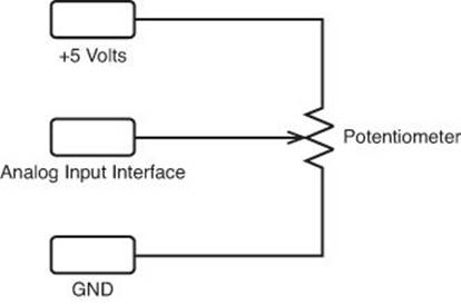
FIGURE 15.2 The analog input test circuit.
Next, you need to create a sketch to read the analog interface and display the retrieved value. To do that, follow these steps:
1. Open the Arduino IDE, and then enter this code into the editor window:
int input;
void setup() {
Serial.begin(9600);
}
void loop() {
input = analogRead(A0);
Serial.print("The current value is ");
Serial.println(input);
delay(3000);
}
2. Save the sketch as sketch1501.
3. Click the Upload icon to verify, compile, and upload the sketch code to the Arduino unit.
4. Open the serial monitor to run the sketch and view the output.
5. As the sketch runs, rotate the potentiometer control arm and look at the values output in the serial monitor.
I placed a delay function at the end of the loop function so that the output doesn’t continually stream to the serial monitor. As you rotate the potentiometer control arm, a delay will occur in the output that you see. You should see different values appear in the serial monitor output, as shown in Figure 15.3.
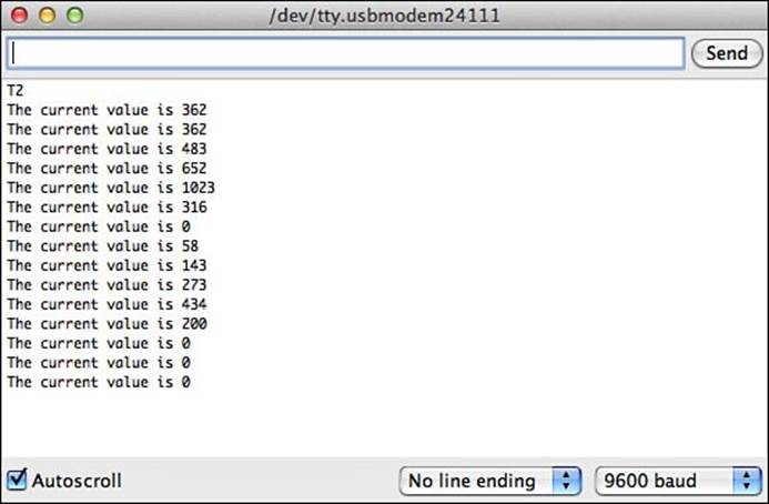
FIGURE 15.3 The Arduino output as you change the input voltage.
When you get to one end of the control arm rotation, the value returned by the analogRead function should be 0, indicating that no voltage is being applied to the analog input. When you get the opposite end of the control arm rotation, the value should be 1023, indicating that all 5 volts are being applied to the analog input.
Modifying the Input Result
By default, the analogRead function returns the detected voltage level as an integer value from 0 to 1023. It’s up to your sketch to determine just what that value means. Fortunately, you can use a couple of functions in your sketches to help manage the values that you have to work with. This section covers those functions and shows how to use them.
Limiting the Input Values
You may run into a situation where you don’t want your sketch to act on very low or very high values in the analog input signal range. For example, you may need a minimum voltage to control a motor, so your sketch needs to ignore any voltages detected on the analog input below a set threshold value.
To do that, you can use the constrain function:
constrain(value, min, max)
The min and max parameters define the minimum and maximum values returned by the constrain function. The value parameter is the value that you want tested by the constrain function. If the value is lower than the min value specified, the constrain function returns the minvalue. Likewise, if the value is larger than the max value specified, the constrain function returns the max value. For all other values between the min and max values, the constrain function returns the actual value.
You can test this out by adding the constrain function to the sketch1501 code that you used for the example:
void loop() {
input = constrain(analogRead(A0), 250, 750);
Serial.print("The current value is ");
Serial.println(input);
delay(3000);
}
Now as you run the program, you should see that the minimum value retrieved will be 250 instead of 0, and the maximum value retrieved will be 750 instead of 1023.
Mapping Input Values
You may have noticed that one downside to using the constrain function is that it makes for a large dead area below the minimum value and above the maximum value. For example, as you turn the potentiometer’s control arm, the output value stays at 250 until the output actually gets above 250. This can prove impractical at times because it makes it more difficult to scale the input device to produce meaningful output values.
One solution to that problem is to use the map function:
map(value, fromMin, fromMax, toMin, toMax);
The map function has five parameters:
![]() value—The value to scale.
value—The value to scale.
![]() fromMin—The minimum value in the original range.
fromMin—The minimum value in the original range.
![]() fromMax—The maximum value in the original range.
fromMax—The maximum value in the original range.
![]() toMin—The minimum value in the mapped range.
toMin—The minimum value in the mapped range.
![]() toMax—The maximum value in the mapped range.
toMax—The maximum value in the mapped range.
In a nutshell, the map function can alter the range of a value from one scale to another. For example, if you want to change the range of the analog input to 0 through 255 rather than 0 through 1023, you use the following:
input = map(analodRead(A0), 0, 1023, 0, 255);
Now as you rotate the potentiometer control arm, the output will be between 0 and 255. You can test this out by adding the map function to the sketch1501 code that you used for the example:
void loop() {
input = map(analogRead(A0), 0, 1023, 0, 255);
Serial.print("The current value is ");
Serial.println(input);
delay(3000);
}
Now when you run the sketch, you’ll notice that the values don’t change as quickly as with the wider range. However, now you don’t have a large dead spot before the minimum value or after the maximum value.
Using Input Mapping
One nice feature of the map function is that you can restrict the final values returned by the input to a predetermined result set. You can then use that result set in a switch statement to run code based on a range of the input values.
This example demonstrates how to do just that.
![]() Try It Yourself: Mapping Input Values
Try It Yourself: Mapping Input Values
You can use the map function to map input values to any result set range that you need in your application. In this example, you map the input to one of three values (1 through 3), and then use that result to light a specific LED.
This example uses the same potentiometer circuit you created for the first example, plus it uses the traffic signal circuit that you used for sketch1401 in Hour 14, “Working with Digital Interfaces.” First, build the hardware for the example:
1. Keep the potentiometer connected to analog interface A0 that you used for the sketch1501 circuit on the breadboard.
2. Add the traffic signal circuit that you used from sketch1401. The final circuit diagram is shown in Figure 15.4. You can use three different-colored LEDs, or you can use three of the same color LED.
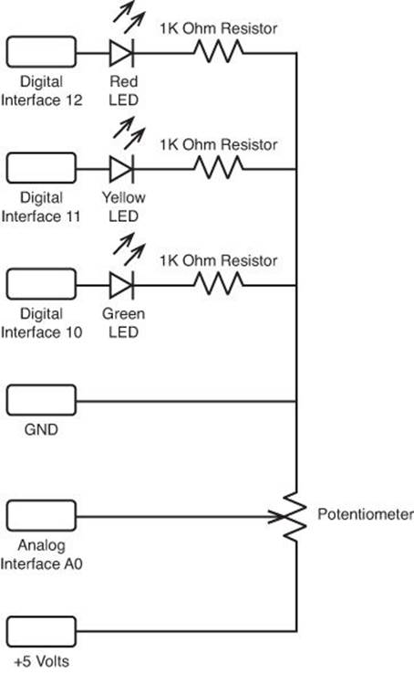
FIGURE 15.4 The complete traffic signal diagram.
The three LED’s are connected to digital interfaces 10, 11, and 12. You control each LED using the digitalWrite function to provide a HIGH signal to light the LED, or a LOW signal to turn off the LED. The next step is to build the sketch to control the LEDs using the potentiometer. Follow these steps for that:
1. Open the Arduino IDE, and then enter this code into the editor window:
int input;
void setup() {
pinMode(10, OUTPUT);
pinMode(11, OUTPUT);
pinMode(12, OUTPUT);
digitalWrite(10, LOW);
digitalWrite(11, LOW);
digitalWrite(12, LOW);
}
void loop() {
input = map(analogRead(A0), 0, 1023, 1, 3);
switch(input) {
case 1:
stoplight();
break;
case 2:
yieldlight();
break;
case 3:
golight();
break;
}
}
void stoplight() {
digitalWrite(10, LOW);
digitalWrite(11, LOW);
digitalWrite(12, HIGH);
}
void yieldlight() {
digitalWrite(10, LOW);
digitalWrite(11, HIGH);
digitalWrite(12, LOW);
}
void golight() {
digitalWrite(10, HIGH);
digitalWrite(11, LOW);
digitalWrite(12, LOW);
}
2. Save the sketch code as sketch1502.
3. Click the Upload icon to verify, compile, and upload the sketch to your Arduino unit.
4. Turn the potentiometer control arm to different positions and watch the LEDs as they light up.
As you turn the potentiometer control arm, the analogRead function returns a different value from 0 to 1023. The map function maps that result to the 1 to 3 range. The switch function executes the appropriate case statement based on the mapped value. Each case statement runs a separate function to light one of the three LEDs.
Changing the Reference Voltage
By default, the Arduino assigns the largest digital value (1023) when a +5 voltage value is present on the analog input. This is called the reference voltage. The digital output values are based on the percentage of the reference voltage the analog input signal is.
The Arduino allows you to change the reference voltage to use a different scale. Instead of 1023 being assigned to +5 volts, you can change it so the analogRead function produces the 1023 value at +1.1 volts. You do that using the analogReference function:
analogReference(source);
The source parameter value specifies what reference to use for the analog-to-digital conversion. You can use either a built-in internal reference source for the Arduino, or you can use your own external reference source. This section shows both methods for changing the reference voltage used on the Arduino.
Using an Internal Reference Voltage
The Arduino can provide a separate internal reference voltage for analog input signals besides the default +5 volts. To do that, you specify the INTERNAL label for the analogReference function:
analogReference(INTERNAL);
For most Arduino models, the internal reference voltage is +1.1 volts. The Arduino Mega model uses a separate internal reference voltage that can generate two separate values: +1.1 or +2.56 volts. Because the Mega can generate two separate input reference voltages, it has two separate labels:
![]() INTERNAL1V1 for the +1.1 volt reference
INTERNAL1V1 for the +1.1 volt reference
![]() INTERNAL2V56 for the +2.56 volt reference
INTERNAL2V56 for the +2.56 volt reference
When you change the reference voltage, the Arduino bases the 0 through 1023 digital value on the new reference voltage. So, when the input voltage is 1.1, it returns a 1023 value.
Using an External Reference Voltage
You can also provide your own reference voltage for the analogRead function. You do that by using the AREF pin on the Arduino header. Just apply the voltage that you want to use as the maximum value to the AREF pin, and set the analogReference function to EXTERNAL:
analogReference(EXTERNAL);
Now when the input analog voltage reaches the reference voltage value, the Arduino returns a 1023 value, and scales the other voltages accordingly.
Watch Out!: Reference Voltage Values
The Arduino can only handle input values of +5 volts or less, so you can’t increase the reference voltage to more than +5 volts. If you need to detect voltages larger than +5 volts, you must use a resistor to decrease the input voltage to within the acceptable input range for the Arduino. Hour 18, “Using Sensors,” dives into this topic in more detail.
Analog Output
The PWM feature on the Arduino enables you to simulate an analog output voltage on specific digital interfaces. The function to use the PWM feature is the analogWrite:
analogWrite(pin, dutycycle);
The pin parameter specifies the digital interface number to use. You don’t need to use the pinMode function to set the digital interface mode; the analogWrite function will do that for you automatically.
The dutycycle parameter specifies the amount of time the digital pulse is set to HIGH. What complicates things is that the duty cycle specified for the analogWrite function isn’t a percentage, but a value from 0 to 255. The 255 value creates a 100% duty cycle signal, generating a +5 analog voltage from the digital interface. The values between 0 and 255 scale the analog output voltage accordingly.
Using the Analog Output
The following example demonstrates how to use the PWM ports on an Arduino to output an analog signal.
![]() Try It Yourself: Generating an Analog Output
Try It Yourself: Generating an Analog Output
In this example, you use a potentiometer to control the brightness of two LEDs connected to PWM interfaces on the Arduino. You use the same circuit that you built for the sketch1502 example. As it turns out, digital interfaces 10 and 11 that we used for two of the traffic signal interfaces also support PWM output. That means you can control the voltage applied to them using the analogWrite function.
You just need to write a sketch that reads the analog value from the potentiometer, and then changes the output voltages on digital interfaces 10 and 11 based on that analog voltage. Follow these steps to do that:
1. Open the Arduino IDE, and then enter this code into the editor window:
int input;
void setup() {
}
void loop() {
input = map(analogRead(A0), 0, 1023, 0, 255);
analogWrite(10, input);
analogWrite(11, (255-input));
}
2. Save the sketch code as sketch1503.
3. Click the Upload icon to verify, compile, and upload the sketch code to your Arduino unit.
4. Rotate the potentiometer control arm to change the voltage value present on the analog input pin.
The sketch1503 code maps the input value received from the A0 analog input to the 0 through 255 range, and then uses that value as the duty cycle for the PWM signal send out on digital interfaces 10 and 11. Notice that the duty cycle for interface 11 will be the opposite as that applied to interface 10. (When the input value is 0, interface 11 will have a duty cycle of 255.) This will cause one LED to get brighter as the other gets dimmer, and vice versa.
As you rotate the potentiometer control arm, you should notice that the LEDs get brighter or dimmer. At one end of the rotation, one LED should go completely out, showing 0 volts on the analog output, and the other should go to maximum brightness, showing +5 volts on the analog output. Then at the opposite end of the rotation, the opposite lights should go out and get bright.
Summary
This hour explored how you can use the Arduino to read and generate analog signals. The Arduino Uno supports six analog input interfaces, labeled A0 through A5. You use the analogRead function to read values from those interfaces. The analogRead function returns an integer value from 0 to 1023, based on the signal level present on the interface. You can change the range of the values using either the constrain or map functions.
All Arduino models support generating analog output signals using pulse-width modulation. You use the analogWrite function to do that. The analogWrite function specifies the digital interface to use for the output, along with the duty cycle, which determines the level of the analog output signal.
This next hour shows you how to use interrupts in your Arduino programs. Interrupts enable you to interrupt your sketch whenever a signal change is detected on an interface. Using interrupts, you don’t have to worry about constantly polling an interface to wait for a signal change.
Workshop
Quiz
1. What function should you use to change the range of the analogRead output?
A. pinMode
B. map
C. switch
D. case
2. The analogWrite function uses a DAC on the Arduino Uno to convert the digital value to an analog value. True or false?
3. What code would you write to remap the output of analog interface A2 to a range of 1 to 10?
Answers
1. B. The map function allows you to map the original range of 0 to 1023 from the analogRead output to another range.
2. False. The analogWrite function uses pulse-width modulation to simulate an analog output signal using the digital interfaces.
3. You could use the following line:
map(analogRead(A2), 0, 1023, 1, 10);
Q&A
Q. Can the Arduino output larger analog voltages?
A. No, the Arduino can only output +5 volts. If you need to generate larger analog voltages, you must create an external circuit that can increase the analog output generated by the Arduino.
Q. How much current does the Arduino generate for the output analog signal?
A. The Arduino generates 40mA of current from the PWM signal.
All materials on the site are licensed Creative Commons Attribution-Sharealike 3.0 Unported CC BY-SA 3.0 & GNU Free Documentation License (GFDL)
If you are the copyright holder of any material contained on our site and intend to remove it, please contact our site administrator for approval.
© 2016-2026 All site design rights belong to S.Y.A.