Sams Teach Yourself Arduino Programming in 24 Hours (2015)
Part III: Arduino Applications
Hour 16. Adding Interrupts
What You’ll Learn in This Hour:
![]() What are interrupts
What are interrupts
![]() How to use external interrupts
How to use external interrupts
![]() How to use pin change interrupts
How to use pin change interrupts
![]() How to use timer interrupts
How to use timer interrupts
Hour 14, “Working with Digital Interfaces,” showed you the basics of how to read data from a digital interface. Sometimes how your sketch reads data on the digital interface can be important. You might sometimes need to detect exactly when a specific action happens on an external circuit, such as when a sensor signal transitions from a LOW to a HIGH value. If your sketch just checks the interface periodically, it may miss the transition when it happens. Fortunately, the Arduino developers have created a way for our sketches to watch for events on digital interfaces, and handle them when they occur. This hour discusses how to use interrupts to watch for events and demonstrates how to use them in your sketches.
What Are Interrupts?
So far in your sketches, you’ve been writing code that checks the digital interface at a specific time in the sketch. For example, in the traffic signal sketch in Hour 14, the code only checks the button position after the yellow LED lights. This method of retrieving data from an interface is called polling.
With polling, the sketch checks, or polls, a specified interface at a specific time to see if a signal has changed values. The more times you poll the interface in your sketch loop, the quicker the sketch can respond to a signal change on the interface.
However, a limit applies to that. Your sketch can’t poll the interface all the time; it might have to do other things in the meantime.
A more practical way of watching for interface signal changes is to let the interface itself tell you when the signal changes. Instead of having the sketch constantly poll the interface looking for a signal change, you can program the sketch to interrupt whatever it’s doing when the signal changes on the interface. This is aptly called an interrupt.
Interrupts trigger actions based on different types of changes in the digital signal value. You can program your sketch to watch for three basic types of signal changes:
![]() Falling signal values from HIGH to LOW
Falling signal values from HIGH to LOW
![]() Rising signal values from LOW to HIGH
Rising signal values from LOW to HIGH
![]() Any type of signal change from one value to the opposite value
Any type of signal change from one value to the opposite value
When the Arduino detects an interrupt, it passes control of the sketch to a special function, called an interrupt service routine (ISR). You can code the ISR to perform whatever actions need to happen when the interrupt triggers.
More than one type of interrupt is available on the Arduino. The next section describes the different types and discusses when to use each type.
Types of Interrupts
The ATmega microprocessor chip used in the Arduino supports three types of interrupts:
![]() External interrupts
External interrupts
![]() Pin change interrupts
Pin change interrupts
![]() Timer interrupts
Timer interrupts
Each type of interrupt works the same way, but is generated by a different trigger in the Arduino. This section discusses the differences between these three types of interrupts.
External Interrupts
External interrupts are triggered by a change in a digital interface signal connected to the Arduino. The ATmega microprocessor chip has built-in hardware support for handling external interrupts. The hardware continually monitors the signal value present on the digital interface and triggers the appropriate external interrupt when it detects a signal change.
By using a hardware interface, external interrupts are very fast. As soon as the digital interface detects the signal change, the microprocessor triggers the external interrupt that your sketch can catch.
The hardware external interrupts are referenced separate from the digital interfaces that they monitor. The external interrupts are named INTx, where x is the interrupt number. The first external interrupt is INT0. Those are the numbers you’ll need to use in your sketches to reference the external interrupt to monitor.
The downside to external interrupts is that not all digital interfaces have the hardware to generate them. Each Arduino model has a limited number of digital interfaces that support generating external interrupts. Table 16.1 shows the digital interface support for external interrupts on the different Arduino models.
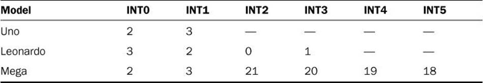
TABLE 16.1 Arduino Support for External Interrupts
For example, on the Arduino Uno model, the INT0 interrupt signal monitors digital interface 2, and the INT1 interrupt signal monitors digital interface 3. Those are the only two digital interfaces on the Uno model that support external interrupts. The Leonardo Arduino model can support four external interrupts, and the Mega Arduino model can support six.
Because external interrupts are generated by the ATmega microprocessor, support for them is already built in to the Arduino programming language. You don’t need to load any external libraries to use external interrupts in your sketches.
Pin Change Interrupts
Pin change interrupts are software driven instead of hardware driven. The benefit of pin change interrupts is that the Arduino generates a pin change interrupt for any type of signal change on any interface. Although this enables you to detect signal changes from any interrupt, there’s a catch.
The catch is that your sketch code must determine just why the pin change interrupt was generated. It has to decode which interface generated the pin change interrupt, and based on what type of signal change.
Fortunately for us, some Arduino developers have created the PinChangeInt library to help out with decoding pin change interrupts that the Arduino generates. It allows you to monitor specific interrupts and to specify the ISR the Arduino runs when the interrupt occurs. This makes handling pin change interrupts almost as easy as working with external interrupts.
Unfortunately, the Arduino IDE environment doesn’t install the PinChangeInt library by default, so you’ll have to do some work to get that installed.
Timer Interrupts
The last type of interrupt that you can use in the Arduino is timer interrupts. Instead of triggering an interrupt based on an event on a digital interface, timer interrupts trigger an interrupt based on a timing event, sort of like an egg timer.
With timer interrupts, your sketch can define an ISR function to trigger at a preset time in the sketch code. When the timer in the Arduino reaches that time, the Arduino automatically triggers the ISR function and runs the function code.
Timer interrupts can come in handy if you need to perform tasks at preset times in the sketch, such as recording a sensor value every 5 minutes. You just set a timer interrupt to trigger every 5 minutes, and then set code in the ISR function to read and record the sensor value.
Using External Interrupts
Coding external interrupts in your sketches is a fairly straightforward process. To use external interrupts, you just need to add two things to your sketch:
![]() Set the external interrupt to watch
Set the external interrupt to watch
![]() The ISR function to run when the interrupt triggers
The ISR function to run when the interrupt triggers
The first step is to define which external interrupt to watch. You do that using the attach Interrupt function:
attachInterrupt(interrupt, isr, mode);
The interrupt parameter defines the external interrupt signal to monitor. For the Arduino Uno model, this value will be either 0 for monitoring interrupt INT0 on digital interface 2, or 1 for monitoring interrupt INT1 digital interface 3.
The isr parameter defines the name of the ISR function the Arduino runs when the external interrupt triggers. The Arduino halts operation in the main sketch code and immediately jumps to the ISR function. When the ISR function finishes, the Arduino jumps back to where it left off in the main sketch code.
The mode parameter defines the signal change that will trigger the interrupt. You can set four types of external interrupt modes:
![]() RISING—Signal changes from LOW to HIGH.
RISING—Signal changes from LOW to HIGH.
![]() FALLING—Signal changes from HIGH to LOW.
FALLING—Signal changes from HIGH to LOW.
![]() CHANGE—Any type of signal value change.
CHANGE—Any type of signal value change.
![]() LOW—Triggers on a LOW signal value.
LOW—Triggers on a LOW signal value.
The LOW interrupt trigger can be somewhat dangerous because it will continually trigger as long as the interface signal is at a LOW value, so be careful with that one. The others are fairly self-explanatory.
Watch Out!: ISR Speed
You want to be aware of a few do’s and don’ts regarding the code that you can use in an ISR function. The idea is to make the ISR code as short and fast as possible, because the Arduino holds up all other processing while running the ISR function. While running the ISR function, the Arduino also ignores any other interrupts that may be generated, so your sketch could miss other interrupts in the process.
Also, don’t use the Serial library methods to output text to the serial monitor inside of an ISR function. The Serial library uses interrupts to send data out the serial ports, which won’t work in the ISR function because the Arduino ignores interrupts inside the ISR function!
When your sketch is finished monitoring external interrupts, you should use the detach Interrupt function to disable them:
detachInterrupt(interrupt);
Just specify the interrupt number that you previously set in the attachInterrupt function to disable it.
Testing External Interrupts
Now that you’ve seen the basics on how to use external interrupts, let’s work on an example that demonstrates using them in an Arduino sketch.
![]() Try It Yourself: Using External Interrupts in a Sketch
Try It Yourself: Using External Interrupts in a Sketch
In this example, you revisit the traffic signal sketch that you created in Hour 14 in the “Experimenting with Digital Input” section. If you remember, sketch1402 used a switch to change the time value assigned to the green LED state. The downside was that you had to press and hold the switch at a specific time in the sketch for it to detect the change.
For this example, you use an external interrupt to control the LED timing. This allows you to press the switch at any time in the traffic light cycle to change the green LED time allocation.
This example requires that you rebuild the traffic signal circuit used for sketch1402 from Hour 14, but moving the switch to the digital interface 2 pin on the Arduino to trigger the external interrupt. The components required for the example are as follows:
![]() Three LEDs (one red, one yellow, and one green)
Three LEDs (one red, one yellow, and one green)
![]() Four 1K ohm resistors (color code brown, black, red)
Four 1K ohm resistors (color code brown, black, red)
![]() A momentary contact switch
A momentary contact switch
![]() A breadboard
A breadboard
![]() Six jumper wires
Six jumper wires
First, follow these instructions for building the traffic signal hardware required for the example:
1. Place the three LEDs on the breadboard so that the short leads are all on the same side and that the two leads straddle the space in the middle of the board so that they’re not connected. Place them so that the red LED is at the top, the yellow LED in the middle, and the green LED is at the bottom of the row.
2. Connect a 1K ohm resistor between the short lead on each LED to a common rail area on the breadboard.
3. Connect a jumper wire from the common rail area on the breadboard to the GND interface on the Arduino.
4. Connect a jumper wire from the green LED long lead to digital interface 10 on the Arduino.
5. Connect a jumper wire from the yellow LED long lead to digital interface 11 on the Arduino.
6. Connect a jumper wire from the red LED long lead to digital interface 12 on the Arduino.
7. Place the momentary contact switch on the breadboard under the LEDs so that the switch straddles the center divide of the breadboard.
8. Connect a jumper wire from digital interface 2 on the Arduino to one of the switch pins.
9. Connect the other switch pin to the GND rail on the breadboard.
10. Connect a jumper wire from the 5V pin on the Arduino to a common rail area on the breadboard.
11. Connect a 1K ohm resistor from the row that has the left side of the switch pin connected to digital interface 2 to the breadboard 5V common rail area.
By The Way: Resistors and LEDs
The size of the resistor to use with the LEDs depends on the amount of current the LEDs you use can handle. The Arduino outputs 40mA of current, so for most larger electronic circuit LEDs, you need only a 1K ohm resistor to limit the current. If you use a smaller-sized LED such as the ones built in to the Arduino, you must use a larger-sized resistor, such as a 10K ohm, to limit the current applied to the LED.
That completes the electronics for the circuit. Figure 16.1 shows the circuit diagram for the completed circuit.
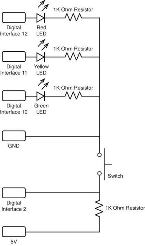
FIGURE 16.1 The external interrupt test circuit.
This circuit re-creates our standard traffic signal light setup using digital interfaces 10, 11, and 12 to control the traffic signal LEDs, plus adds a switch to digital interface 2 to trigger the INT0 interrupt.
The switch uses a 1K ohm resistor as a pullup resistor to tie digital interface 2 to a HIGH signal when the switch isn’t pressed. When you press the switch, it pulls the interface LOW.
The circuit uses the built-in LED on digital interface 13 to monitor when the interrupt is triggered. (Remember, you can’t use the Serial.print function inside an ISR function.) When the L led on the Arduino unit lights, the timer is set to a 10-second interval for the green LED.
Now you’re ready to create the sketch for the example. Follow these steps to do that:
1. Open the Arduino IDE, and then enter this code into the editor window:
int stop = 6;
int yield = 2;
int go = 6;
void setup() {
Serial.begin(9600);
pinMode(13, OUTPUT);
pinMode(10, OUTPUT);
pinMode(11, OUTPUT);
pinMode(12, OUTPUT);
digitalWrite(8, LOW);
digitalWrite(10, LOW);
digitalWrite(11, LOW);
digitalWrite(12, LOW);
attachInterrupt(0, changeTime, FALLING);
}
void loop() {
stoplight(stop);
golight(go);
yieldlight(yield);
}
void stoplight(int time) {
digitalWrite(10, LOW);
digitalWrite(11, LOW);
digitalWrite(12, HIGH);
Serial.println("Light mode: Stop");
delay(time * 1000);
}
void yieldlight(int time) {
digitalWrite(10, LOW);
digitalWrite(11, HIGH);
digitalWrite(12, LOW);
Serial.println("Light mode: Yield");
delay(time * 1000);
}
void golight(int time) {
digitalWrite(10, HIGH);
digitalWrite(11, LOW);
digitalWrite(12, LOW);
Serial.print("Light mode: Go - ");
Serial.println(time);
delay(time * 1000);
}
void changeTime() {
if (go == 6) {
go = 10;
digitalWrite(13, HIGH);
} else {
go = 6;
digitalWrite(13, LOW);
}
}
2. Save the sketch as sketch1601.
3. Click the Upload icon to verify, compile, and upload the sketch to your Arduino unit.
4. Open the serial monitor to run the sketch and view the output.
You should recognize most of the code in this sketch from Hour 14. It creates separate functions to control the stop, yield, and go states of the traffic signal, just like before. However, this version uses the attachInterrupt function to tell the Arduino to monitor the input on digital interface pin 2 (INT0). Digital interface 2 is wired in a pullup circuit, providing a HIGH signal value by default. When you press the switch button, the circuit pulls the digital interface 2 pin to ground, causing the signal to fall to a LOW value, triggering the FALLING interrupt on INT0.
The attachInterrupt function catches the falling interrupt, and runs the changeTime ISR function defined in the sketch. The changeTime function changes the value of the go variable, which controls how long the green LED stays lit. It also changes the fourth LED to indicate when the go variable is 10 (the LED will light) or 6 (the LED will be off). This feature allows you to peek inside the ISR function and easily see when it triggers.
When you run the sketch, you can press the switch button at any time in the traffic light cycle to change the length assigned to the green LED.
Watch Out!: Switch Bounce
One downside to using interrupts is that they are very sensitive. Every time the interface signal changes, it generates a new interrupt. You may have noticed that if you’re not careful pressing the switch button, it may trigger two or more interrupts with one press. This is called switch bounce.
To help minimize switch bounce, place a capacitor across the two switch pins. The capacitor stores electricity when the switch is open, and discharges when the switch is closed. The change won’t actually register on the digital interface until the capacitor fully discharges.
If the switch bounces while the capacitor is discharging, the discharge will override the bounce, forcing the signal to stay HIGH. This helps mask short switch bounces in the circuit, but it does reduce the sensitivity of the switch.
Using Pin Change Interrupts
Thanks to the PinChangeInt library, using pin change interrupts isn’t too different from using external interrupts. You just specify the pin number that you want to monitor, the type of signal change you want to detect, and the ISR function to run when the interrupts occurs.
This section shows you how to install the PinChangeInt library and use it in your sketches.
Installing the PinChangeInt Library
The PinChangeInt library is packaged a little differently than the standard Arduino libraries, making it a little harder to import into your Arduino IDE environment. Here are the steps you need to follow to import the PinChangeInt library into your Arduino IDE environment:
1. Open a browser and navigate to the PinChangeInt web page: http://code.google.com/p/arduino-pinchangeint/.
2. Click the Downloads tab at the top of the main web page.
3. From the Downloads page, click the Download icon for the latest nonbeta version available (at the time of this writing, version 1.72).
4. Click the Save button to download the zip file to your workstation.
5. Open the zip file on your system, and extract the PinChangeInt folder from the zip file to a temporary location.
6. Move the PinChangeInt folder from the temporary location to the libraries folder under your Arduino installation location (normally under the Documents\Arduino folder for your user account in both Windows and OS X).
7. If you have the Arduino IDE open, close it and reopen it so it can recognize the new PinChangeInt library.
Watch Out!: Using the Import Library
Unfortunately, the PinChangeInt zip file contains three separate library folders, so you can’t use the Arduino IDE Import Library feature shown in Hour 13, “Using Libraries.” Instead, you have to extract the PinChangeInt folder from the distribution zip file and manually copy it into the libraries folder for the Arduino IDE.
The PinChangeInt library is now imported into your Arduino IDE environment. When you go to the Import Library submenu, the PinChangeInt library should appear under the Contributed section of the library listing.
Experimenting with Pin Change Interrupts
After importing the PinChangeInt library into your Arduino IDE environment, you can easily use it to track interrupts on any digital interface on the Arduino. First, you must import the library into your sketch by using the Import Library option of the Sketch menu item. This adds a#include directive to your sketch:
#include <PinChangeInt.h>
Next, you need to set the digital interface that you want to use for the interrupt trigger to input mode:
pinMode(7, INPUT);
Finally, you use the special PCintPort object that’s created in the library to access the attachInterrupt method. That line looks like this:
PCintPort::attachInterrupt(7, changeTime, FALLING);
With the PinChangeInt attachInterrupt method, you specify the pin number of the digital interface as the first parameter, the ISR function to call as the second parameter, and the signal change to monitor as the third parameter.
Let’s go through an example of using the PinChangeInt library in your sketch.
![]() Try It Yourself: Using the Pin Change Interrupt
Try It Yourself: Using the Pin Change Interrupt
You can easily convert the external interrupt example used in sketch1601 to use a pin change interrupt. Use the circuit that you built for the sketch1601 example, and follow these steps:
1. Open the Arduino IDE, and then open the sketch1601 sketch.
2. Select Sketch from the menu bar at the top of the Arduino IDE.
3. Select Import Library, and then select the PinChangeInt library.
4. Change the setup function code to look like this:
void setup() {
Serial.begin(9600);
pinMode(7, INPUT);
pinMode(13, OUTPUT);
pinMode(10, OUTPUT);
pinMode(11, OUTPUT);
pinMode(12, OUTPUT);
digitalWrite(13, LOW);
digitalWrite(10, LOW);
digitalWrite(11, LOW);
digitalWrite(12, LOW);
PCintPort::attachInterrupt(7, changeTime, FALLING);
}
5. Save the new sketch as sketch1602.
6. Move the jumper wire from the switch that was connected to digital interface 2 to digital interface 7.
7. Click the Upload icon to verify, compile, and upload the sketch to your Arduino unit.
8. Open the serial monitor to run the sketch and view the output.
The updated code sets a pin change interrupt on digital interface 7 and watches for a falling signal change. When you press the switch, it triggers the pin change interrupt, and changes the time allocated to the green LED in the traffic signal. Now with pin change interrupts, you can place the switch on any digital interrupt and monitor when it changes.
Working with Timer Interrupts
Timer interrupts allow you to set interrupts that trigger at a preset time period while your sketch runs. All Arduino models include at least one timer that you can access with your sketch code, called Timer1. The Arduino Mega model provides three separate timers that you can use.
To access the timer, you need to use special software. Again, the Arduino developer community has come to our rescue and has provided an easy-to-use library for us. The Timer One library provides everything we need to utilize the Timer1 internal timer in your Arduino unit.
This section demonstrates how to get and install the Timer One library, plus shows an example of how to use it in your own Arduino sketches.
Downloading and Installing Timer One
Similar to the PinChangeInt library, you’ll have to go out to the Internet and download the Timer One library to install it in your Arduino IDE environment. Here are the steps to do that:
1. Open a browser and navigate to the Timer One Web page: http://code.google.com/p/arduino-timerone/.
2. Click the Downloads link at the top of the web page.
3. Click the Download icon for the latest release version of the Timer One library (called TimerOne-v9.zip at the time of this writing).
4. Save the file to a location on your workstation.
5. Open the downloaded zip file, and then extract the TimerOne-v9 folder to a folder called TimerOne in a temporary location (you’ll have to rename the folder to remove the dash for it to work).
6. Copy the TimerOne folder to the libraries folder in your Arduino IDE environment.
After importing the Timer One library into your Arduino IDE, you’re ready to use it in your sketches.
Testing Timer Interrupts
Let’s work through an example of using the Timer One library. For this example, you create a sketch that blinks the built-in LED connected to the digital interface 13 pin on the Arduino using the Timer One library. Just follow these steps:
1. Open the Arduino IDE, click the Sketch menu bar item, and then under Import Library, select the Timer One library.
2. Enter this code into the editor window:
#include <TimerOne.h>
int state = 0;
void setup() {
pinMode(13, OUTPUT);
digitalWrite(13, state);
Timer1.initialize(1000000);
Timer1.attachInterrupt(blinkme);
}
void loop() {
}
void blinkme() {
state = !state;
digitalWrite(13, state);
}
3. Save the sketch as sketch1603.
4. Click the Upload icon to verify, compile, and upload the sketch to your Arduino unit.
The sketch1603 code uses methods in the Timer1 class object defined in the Timer One library. This sketch uses two methods from that library:
Timer1.initialize(time);
Timer1.attachInterrupt(isr);
The initialize method defines the amount of time between triggering the timer interrupt. The time value is defined in microseconds, so to trigger the interrupt every second, you’ll need to enter the value 1000000.
The attachInterrupt method defines the ISR function to call when the timer interrupt triggers.
In this example, I created an integer variable called state that toggles between HIGH and LOW values on each timer interrupt. When the state variable is set to a HIGH value, the LED that is connected to digital interface 13 lights up. When the state variable is set to a LOW value, the LED is not lit. The timer interrupt triggers the blinkme function every 1 second, which causes the LED to change states every second. Feel free to change the value set for the timer interval and watch how it changes the blink rate of the LED.
Ignoring Interrupts
Sometimes you might not want your sketch code interrupted by events (such as a time-sensitive part of the sketch code). In those situations, you can disable interrupts so that they don’t trigger the ISR function assigned to them. You do that using the nointerrupts function:
nointerrupts();
As you can see, there aren’t any parameters to the nointerrupts function, so you can’t disable a specific interrupt. When you run the nointerrupts statement, all interrupts on the Arduino are ignored.
You can reenable interrupts when your sketch is ready to accept them again using the interrupts function:
interrupts();
Again, as you can see, the interrupts function doesn’t use any parameters, so it enables all interrupts on the Arduino.
Summary
This hour explored the world of interrupts on the Arduino. Interrupts alter the operation of a sketch when a specified event is detected on the Arduino. You can use three types of interrupts on the Arduino. External interrupts are built in to the ATmega microprocessor chip and trigger an interrupt when the microprocessor detects a signal change on a specific digital interface. Most Arduino models support only two external interrupts.
Pin change interrupts are software generated by the microprocessor, but can be set for any digital interface. Unfortunately the sketch must decode the cause of the pin change interrupt, which can be tricky. The PinChangeInt library provides simple functions for us to use to interface with pin change interrupts.
Timer interrupts allow you to set a timer to trigger an interrupt at predefined intervals in the sketch. All Arduino models support one timer interrupt, and the Due, Mega, and Yun models support multiple interrupts.
The next hour covers how to use serial communication techniques to help your Arduino communicate with the outside world. The Arduino supports three different types of serial communication protocols, as discussed in the next hour.
Workshop
Quiz
1. Which type of interrupt should you use to read a sensor value every 5 minutes in your sketch?
A. External interrupt
B. Pin change interrupt
C. Timer interrupt
D. Polling
2. You can use external interrupts on any digital interface on the Arduino. True or false?
3. If you set both the INT0 and INT1 external interrupts, how can you turn off only the INT1 interrupt and keep the INT0 interrupt active?
Answers
1. C. Timer interrupts allow us to set a predefined interval for the interrupt to trigger an ISR function. You can then place code to read the sensor value inside the ISR function.
2. False. Most Arduino models only support two external interrupts, on digital pins 2 and 3.
3. You can use the detachInterrupt(1) function to stop receiving interrupts for INT1, but continue receiving interrupts for INT0.
Q&A
Q. Can you define different ISR functions for different interrupts, or must all the interrupts use the same ISR function?
A. You can define multiple ISR functions and assign each one to a different interrupt.
Q. Can you change the mode of an interrupt from RISING to FALLING?
A. No, you must detach the interrupt first, and then attach a new interrupt with the new mode.
Q. Can I use both external and pin change interrupts at the same time?
A. Yes, but be careful that you don’t assign both to the same digital interface.
All materials on the site are licensed Creative Commons Attribution-Sharealike 3.0 Unported CC BY-SA 3.0 & GNU Free Documentation License (GFDL)
If you are the copyright holder of any material contained on our site and intend to remove it, please contact our site administrator for approval.
© 2016-2026 All site design rights belong to S.Y.A.