Sams Teach Yourself Arduino Programming in 24 Hours (2015)
Part III: Arduino Applications
Hour 18. Using Sensors
What You’ll Learn in This Hour:
![]() The different types of analog sensors available
The different types of analog sensors available
![]() How to use voltage-based sensors
How to use voltage-based sensors
![]() How to work with resistance-based sensors
How to work with resistance-based sensors
![]() How touch sensors work
How touch sensors work
Working with the analog interfaces on the Arduino can be somewhat complex. There are lots of different analog sensors out there, as well as lots of different ways to measure the analog data they produce. This hour takes a closer look at how to work with the different types of analog sensors that you may run into when working with your Arduino.
Interfacing with Analog Sensors
Analog sensors are more difficult to work with than digital sensors. With digital sensors, you only have to worry about detecting one of two possible values (a 0 or a 1). However, analog sensors can produce an infinite number of possible output values. The trick to working with analog sensors is in knowing what type of output the sensor produces and decoding just what the output means.
To convey information using an analog signal, analog sensors typically change one of three different physical electrical properties:
![]() Voltage
Voltage
![]() Resistance
Resistance
![]() Capacitance
Capacitance
You must know the type of analog sensor that your circuit uses to be able to appropriately handle the analog output that it generates. Also, your sketch will need to know how to convert the analog value to meaningful information, such as the temperature or the brightness level.
With analog signals, your Arduino sketch will often need help from some external electronic circuitry to change the signal the sensor produces into some type of usable form. The combination of the electronic circuit and your sketch is what creates the monitoring environment.
The next sections discuss how to monitor each of the three different types of analog sensors you may have to work with.
Working with Voltage
Many analog sensors produce a varying voltage that represents the property they monitor. There are different types of analog sensors that use voltage as the output used in industry, such as the following:
![]() Temperature sensors
Temperature sensors
![]() Light sensors
Light sensors
![]() Motion sensors
Motion sensors
With each of these sensors, the amount of temperature, light, or motion that the sensor detects is represented by the voltage level present at the sensor output.
The good thing about using voltage-based analog sensors is that because the Arduino analog interfaces detect changes in voltage, you often don’t need to provide too much additional electronic circuitry to work with voltage-based sensors. This section covers the different issues you need to consider when working with analog voltages from sensors.
Voltage Range
The first thing to consider when working with voltage-based analog sensors is the voltage range the sensor produces. An upper and lower limit usually applies to the voltage that the sensor produces under the monitoring conditions. For example, the Arduino Uno uses a 5V reference voltage, so the analog input interfaces are based on the maximum sensor voltage being 5V.
However, not all analog sensors are based on a 5V reference voltage. You might have to manipulate the output voltage from the sensor to be able to work with it in the Arduino.
Watch Out!: The Arduino Due
Be careful when using the Arduino Due, Fio, and Pro; they support only 3.3V voltage levels.
Using a Sensor That Matches the Arduino Voltage
The simplest situation is when the sensor outputs a signal that matches the voltage the Arduino can support (3.3V for the Due, or 5V for the other models). In this case, you can just connect the sensor output directly to the Arduino analog input interface, as shown in Figure 18.1.
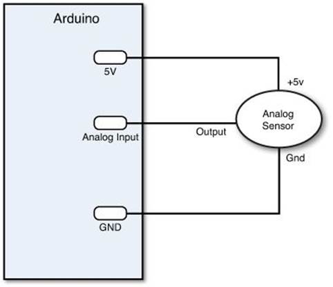
FIGURE 18.1 Connecting a 5V sensor to the Arduino Uno.
Notice from Figure 18.1 that you can also power the sensor directly from the Arduino Uno 5V pin, which provides 5V of power. You will also need to connect the ground for the sensor to the Arduino GND pin to ensure the circuit is complete.
Using Larger Voltages
If the sensor output voltage is larger than what the Arduino supports, you cannot directly connect the sensor output to the analog input interface; otherwise, you may damage your Arduino. Instead, you need to use what’s called a voltage divider circuit to reduce the amount of voltage present on the analog interface.
A voltage divider is two resistors placed in series, with the output taken from the connection between the two resistors, as shown in Figure 18.2.
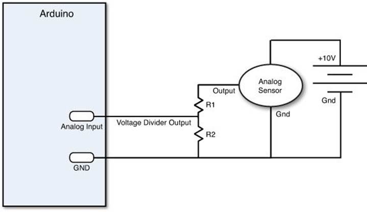
FIGURE 18.2 Using a voltage divider on the analog input interface.
The output of the voltage divider depends on the ratio of the two resistor values. The equation that determines the output voltage is as follows:
output voltage = sensor voltage * (R2 / (R1 + R2))
If both resistors in the voltage divider are the same value, the output voltage will be one half of the sensor voltage. So, if the analog sensor has a maximum output of 10V, you can use two 1K-ohm resistors to ensure that the maximum voltage present at the analog input is less than 5V.
Watch Out!: Common Ground
Whenever you work with a sensor that uses its own power supply, make sure that you connect the ground from the external power supply to the GND pin on the Arduino unit. This ensures the sensor and the Arduino are using the same ground reference. However, don’t connect the power pole of the external power supply to the Arduino 5V pin!
Using Smaller Voltages
The opposite of too much voltage is too little voltage to detect. If the sensor outputs a small voltage, you can connect the sensor directly to the Arduino analog input interface, but you may have trouble reading the changes in the output voltage. The solution to that is to change the voltage reference that the Arduino uses to represent the maximum output value.
To change the voltage reference, you must use the AREF input pin on the Arduino. Just connect the voltage source from the sensor to the AREF pin on the Arduino, as shown in Figure 18.3.
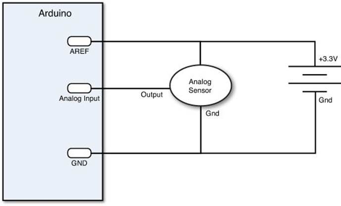
FIGURE 18.3 Changing the reference voltage used for the Arduino analog input.
With the new reference voltage, the Arduino changes the output range to represent the new reference voltage instead of 5V. To get your sketch to use the new reference voltage, you must use the AnalogReference function:
AnalogReference(EXTERNAL);
When you use the EXTERNAL setting, the analogRead function bases its output for a maximum voltage equal to the reference voltage. After you set the analog reference voltage, the analogRead function returns the 1023 value when the voltage on the input interface is the same as the reference voltage.
Sensitivity
Another important issue to consider is the sensor sensitivity. Your Arduino sketch must be able to detect the changes in the voltage sent from the analog sensor, which represent changes in the property that’s being monitored.
The Arduino Uno uses a 10-bit analog-to-digital converter (ADC), which provides 1024 separate output values based on the input voltage level. If your sensor uses 5V as reference, that means the Arduino will produce a value of 0 when the input voltage is 0V, and 1023 when the input voltage is 5V.
By dividing that voltage range, you’ll notice that each step in the output represents about a 0.005V change in the input voltage, or about 5 millivolts (mV). That means the Arduino analog input won’t be able to distinguish voltage changes less than 5mV from the sensor.
However, you may also run into the situation where the Arduino analog input may be too sensitive to changes in the voltage received from the sensor. You may not want your sketch to respond to a 5mV change in the voltage, but rather, only to larger changes.
One solution to that problem is to remap the output range generated by the analogRead function to a smaller range using the map function (see Hour 15, “Interfacing with Analog Devices”). The map function allows you to specify a new range to use for the output:
input = map(analogRead(A0), 0, 1023, 0, 255);
This desensitizes the output from the analogRead function, providing for fewer changes within the range of the sensor. By changing the range to 0 through 255, the input value only changes for changes of 20mV instead of 5mV.
Converting Voltage to Something Useful
The last step in using a voltage-based sensor is to convert the voltage that the Arduino detects to a meaningful value that represents the property that you’re monitoring (such as the temperature of the room, or the amount of light that’s present). Usually this requires having to do a little research on the sensor that you’re using.
Most sensor manufacturers produce a datasheet that documents the range of output of the sensor and the relation to the property that it measures. For example, the TMP36 temperature sensor produces a voltage range from 0.1V for –40 degrees Celsius to 2.0V for 150 degrees Celsius. To display the actual temperature, you’ll need to do a little math in your Arduino sketch. According to the TMP36 datasheet, the relation of the output voltage to the actual temperature uses this equation:
temp in Celsius = (voltage - 500) / 10
Where the voltage value is specified in millivolts.
However, before you use that equation, you must convert the integer value that the analogRead function returns into a millivolt value. A little bit of algebra can help out here.
You know that for a 5000mV (5V) value span the analogRead function will return 1024 possible values. Just use an equation to relate the actual analogRead output value to the known voltage values, and then solve for the voltage variable:
voltage / output = 5000 / 1024
voltage = (5000 / 1024) * output
Using this equation, you can take the output value you retrieve from the analogRead function and determine the voltage present at the analog input. Once you know the voltage, you can use it to find the temperature. Or, if you prefer, you can combine both equations into a single calculation:
tempC = ((5000/1024) * output) - 500) / 10;
Now you can retrieve the temperature directly from the output integer value the analogRead function produces. The next section walks through an example of using this process to determine the temperature using the TMP36 temperature sensor.
Using a Voltage-Based Sensor
This experiment uses the popular TMP36 temperature sensor to detect the temperature and display that temperature in the serial monitor. The TMP36 sensor is common in the Arduino world. You’ll often find it in Arduino kits, including the official Arduino Starter Kit package. It’s also readily available for purchase from many Arduino electronic suppliers such as Adafruit and Newark Electronics.
![]() Try It Yourself: Detecting Temperature
Try It Yourself: Detecting Temperature
In this experiment, you need to connect the TMP36 directly to your Arduino unit. The TMP36 temperature sensor has three leads: power, ground, and the output.
You must power the sensor by connecting the power lead to a voltage source between 2.7 and 5.5V (which makes it ideal for use with both the 5V Arduino Uno and the 3.3V Arduino Due) and connect the ground lead to the Arduino ground. The middle lead produces an output voltage less than 5V, so you can connect that directly to an analog input pin. Figure 18.4 shows the pin outputs on the TMP36 temperature sensor.
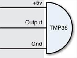
FIGURE 18.4 The TMP36 sensor pins.
Here are the steps to wiring the TMP36 sensor to your Arduino unit:
1. Place the TMP36 sensor on the breadboard so that each lead connects to a separate rail section and that the flat side of the TMP36 case is facing toward the left.
2. Place a jumper wire between the top lead of the TMP36 and the 5V pin on the Arduino.
3. Place a jumper wire between the bottom lead of the TMP36 and the GND pin on the Arduino.
4. Place a jumper wire between the middle lead of the TMP36 and the Analog 0 pin on the Arduino.
That’s all the hardware you need to worry about for this experiment. The next step is to create the sketch code. Just follow these steps to work on that:
1. Open the Arduino IDE and enter this code into the editor window:
int output;
float voltage;
float tempC;
float tempF;
void setup() {
Serial.begin(9600);
}
void loop() {
output = analogRead(A0);
voltage = output * (5000.0 / 1024.0);
tempC = (voltage - 500) / 10;
tempF = (tempC * 9.0 / 5.0) + 32.0;
Serial.print("Sensor Output: ");
Serial.println(output);
Serial.print("Voltage (mv): ");
Serial.println(voltage);
Serial.print("Temp (C): ");
Serial.println(tempC);
Serial.print("Temp (F): ");
Serial.println(tempF);
Serial.println();
delay(5000);
}
2. Save the sketch as sketch1801.
3. Click the Upload icon to verify, compile, and upload the sketch code into your Arduino unit.
4. Open the serial monitor to view the output from the sketch.
The output from the temperature sensor should be somewhat consistent when at room temperature. Try placing your fingers around the sensor and see whether the temperature rises. Then, place an ice cube in a plastic bag, and then place the bag next to the sensor. That should lower the output generated by the sensor.
Working with Resistance Output
Instead of using a voltage output, some analog sensors change their resistance as the characteristic they monitor changes. These types of sensors include the following:
![]() Thermistors: Change resistance due to temperature.
Thermistors: Change resistance due to temperature.
![]() Photoresistors: Change resistance due to light.
Photoresistors: Change resistance due to light.
The problem with resistance sensors is that the Arduino analog interfaces can’t directly detect resistance changes. This will require some extra electronic components on your part.
The easiest way to detect a change in resistance is to convert that change to a voltage change. You do that using our friend the voltage divider, as shown in Figure 18.5.
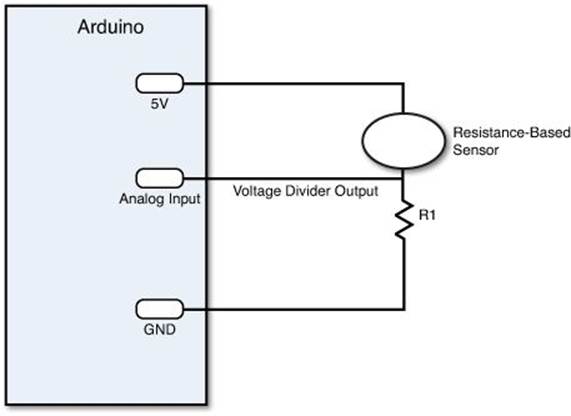
FIGURE 18.5 Using a voltage divider to detect a change in resistance.
By keeping the power source output constant, as the resistance of the sensor changes, the voltage divider circuit changes, and the output voltage changes. The size of resistor you need for the R1 resistor depends on the resistance range generated by the sensor and how sensitive you want the output voltage to change. Generally, a value between 1K and 10K ohms works just fine to create a meaningful output voltage that you can detect in your Arduino analog input interface.
The voltage divider will produce a varying output voltage. As the sensor resistance value increases, the output voltage increases, and as the sensor resistance decreases, the output voltage decreases. At that point, you can use the same sensing tricks that you learned for working with the voltage sensors.
Using a Resistance-Based Sensor
So, the key to using resistance-based sensors is to build a voltage divider circuit to generate the output voltage. The following experiment demonstrates how to do that using a photoresistor to detect light levels.
![]() Try It Yourself: Building a Light Meter
Try It Yourself: Building a Light Meter
In this experiment, you use a common photoresistor (also called a photocell or a light-dependent resistor (LDR)) to detect the amount of light in the room. Photoresistors come in many shapes and sizes. Any type will work for this experiment.
The photoresistor uses two output leads and changes the resistance present on those leads as the light level changes. As the amount of light increases, the resistance of the photoresistor decreases (and vice versa). Many standard Arduino kits come with one or more photoresistors, including the Arduino Start Kit, and they’re also available for purchase from the standard Arduino electronics shops.
Here are the steps for creating the Arduino light meter project. First, you need to build the electronic circuit:
1. Place the photoresistor leads on two separate rails sections on the breadboard.
2. Connect a 10K-ohm resistor (color code brown, black, orange) so that one lead connects to one lead of the photoresistor and the other lead is in another rail on the breadboard.
3. Connect the 5V pin of the Arduino to the free lead on the photoresistor.
4. Connect the GND pin of the Arduino to the free lead on the 10K-ohm resistor.
5. Connect the Analog 0 interface pin on the Arduino to the rail that has both the photoresistor and 10K-ohm resistor leads.
The circuit creates a standard voltage divider, sending the output voltage to the Analog 0 interface pin on the Arduino.
The next step is to create a sketch to read the output values. Follow these steps to do that:
1. Open the Arduino IDE and enter this code into the editor window:
int output;
float voltage;
void setup() {
Serial.begin(9600);
}
void loop() {
output = analogRead(A0);
voltage = output * (5000.0 / 1024.0);
Serial.print("Sensor Output: ");
Serial.println(output);
Serial.print("Voltage (mv): ");
Serial.println(voltage);
Serial.println();
delay(5000);
}
2. Save the sketch as sketch1802.
3. Click the Upload icon to verify, compile, and upload the sketch to your Arduino unit.
4. Open the serial monitor to run the sketch and view the output.
Check the output from the sketch using the normal room lighting, and then try covering the photoresistor with your hand and watch the output. The sensor output value should decrease, indicating a decrease in the voltage present at the analog input.
As the photoresistor receives less light, the resistance value increases, causing less voltage to be output from the voltage divider. As you increase the light on the photoresistor, the resistance value decreases, causing more voltage to be output from the voltage divider.
Using Touch Sensors
Touch sensors use capacitance to detect when an object is being touched. When you touch a metal object, the natural capacitance in your body changes the capacitance present in the object.
The problem with using touch sensors is similar to the problem we ran into with resistance-based sensors; they both don’t directly change output voltage. However, detecting the change in capacitance from a touch sensor is solved using an interesting electrical property.
Capacitors store voltage. The amount of time it takes for a capacitor to fully charge or discharge depends on the amount of resistance present in the circuit, as well as the capacitance of the capacitor. By setting the resistor and capacitor sizes, you can control just how quickly the capacitor charges and discharges. This is called an RC circuit.
You can build a simple RC circuit using the capacitance detected by a touch sensor and a resistor of a known value. Because the resistance value is known, you can determine the capacitance value based on the time it takes for the capacitor to charge. You can tell when a capacitor is fully charged when current starts following past the capacitor in the circuit (until the capacitor is fully charged, no current will flow past it).
So basically, detecting the capacitance change has to do with timing. Just apply a known voltage value to one end of the RC circuit and detect how long it takes for the same voltage to be present at the other end of the circuit. The more capacitance, the longer it takes to detect the output voltage.
To do that, you use two digital input pins on the Arduino. (That’s right, you use digital pins and not analog pins for this.) You set one pin as output to a HIGH value, and then track the amount of time it takes for the other digital input pin to have a HIGH value. The longer it takes, the more capacitance is in the circuit, and most likely, someone is touching the sensor.
Working with Touch Sensors
Fortunately for us, some smart developers have already created an Arduino library to easily detect the timing change between the two digital output pins for us. The CapacitiveSensor library includes all the functions we need to build a capacitive touch sensor project.
This experiment uses the CapacitiveSensor library to detect when a wire is touched.
![]() Try It Yourself: Building a Touch Sensor
Try It Yourself: Building a Touch Sensor
You can build a simple touch sensor using just a resistor, some wire, and your Arduino unit. First, follow these steps to build the circuit:
1. On a breadboard, plug a 1M (mega)-ohm resistor (color code brown, black, green) between two separate rails.
2. Use a jumper wire to connect one lead of the resistor to digital pin 7. This is the Send pin for our circuit.
3. Use a jumper wire to connect the other lead of the resistor to digital pin 5. This is the Receive pin for our circuit.
4. Connect a wire to the rail that contains the digital pin 5 connection, and let the other end of the wire be free.
That completes the touch sensor circuit. The free end of the wire is our sensor. Some experiments also use aluminum foil connected to the end of the wire. Feel free to try that as well. Figure 18.6 shows the diagram for the completed circuit.
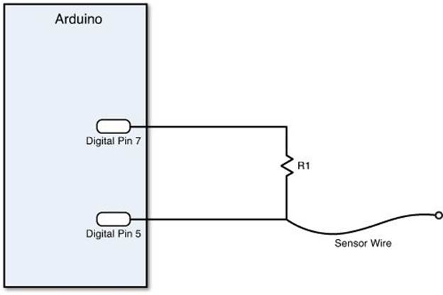
FIGURE 18.6 The touch sensor circuit.
Now you’re ready to build the sketch code. Here are the steps to do that:
1. Download the CapacitiveSensor library from the link on the Arduino Playground website (http://playground.arduino.cc//Main/CapacitiveSensor).
2. Extract the CapacitiveSensor folder from the downloaded zip file and place it in your Arduino libraries folder, usually located in your Documents folder for both Windows and Apple OS X systems.
3. Open the Arduino IDE, and from the menu bar, select Sketch, Import Library, CapacitiveSensor.
4. In the IDE editor window, enter this code:
#include <CapacitiveSensor.h>
CapacitiveSensor Sensor = CapacitiveSensor(7,5);
void setup() {
Serial.begin(9600);
}
void loop() {
long sensorValue = Sensor.capacitiveSensor(30);
Serial.println(sensorValue);
delay(2000);
}
5. Save the sketch as sketch1803.
6. Click the Upload icon to verify, compile, and upload the sketch to your Arduino unit.
7. Open the serial monitor to run the sketch and view the output.
Watch the sensor values that appear in the output when the sensor wire is untouched. Touch the end of the sensor wire and note the change in the sensor value. Next, hold the end of the sensor wire in your fingers and note the change in the sensor value.
Tip: Sensor Sensitivity
You may have to change the sensitivity of the sensor by changing the resistance value of the R1 resistor in the circuit for it to detect the touch. Higher resistance values make the sensor more sensitive to capacitance changes on the wire.
Summary
This hour discussed how to work with different types of analog sensors in your Arduino projects. Voltage-based sensors change the output voltage based on the property they monitor. You may have to limit the voltage present on the Arduino analog input pin using a voltage divider, or change the sensitivity of the input pin using an external reference voltage and the analogReference function. Resistance-based sensors change their resistance as the monitored property changes. To use these types of sensors, you’ll need to create a voltage divider to convert the resistance change to a voltage change. This chapter also covered how to use touch sensors in your Arduino circuits. Touch sensors are based on capacitance changes. To detect the capacitance change, you can build a simple RC circuit and use the CapacitiveSensor library to detect the time change required to trigger a digital input pin.
In the next hour, we’ll turn our attention to another popular Arduino circuit topic: motors. You can use different types of motors in your Arduino projects, and you need to know how to work with each type.
Workshop
Quiz
1. What kind of circuit should you use to decrease the voltage from the sensor?
A. A voltage divider
B. An RC circuit
C. Change the Arduino reference voltage
2. You can connect the output of a resistor-based sensor directly to the Arduino analog interface to detect the sensor output change. True or false?
3. What type of circuit do touch sensors require to detect touch?
Answers
1. A. The voltage divider circuit allows you to decrease a voltage to a value within the range required for the Arduino.
2. False. For a resistance-based sensor, you must use a voltage divider to change the output voltage relative to the change of the sensor resistance.
3. An RC circuit provides a way to detect a change in the capacitance of a touch sensor by measuring the amount of time it takes for the capacitor to charge.
Q&A
Q. Can you use a voltage divider to decrease voltages generated by high-power devices?
A. Yes, but you may lose some sensitivity. By significantly decreasing the voltage, you won’t be able to detect small voltage changes from the original voltage.
Q. Can the Arduino analog interface use sensors that produce AC voltages?
A. Not directly. The Arduino analog interfaces use DC voltages, so you first have to convert the AC output voltage to a DC voltage.
All materials on the site are licensed Creative Commons Attribution-Sharealike 3.0 Unported CC BY-SA 3.0 & GNU Free Documentation License (GFDL)
If you are the copyright holder of any material contained on our site and intend to remove it, please contact our site administrator for approval.
© 2016-2026 All site design rights belong to S.Y.A.