Sams Teach Yourself Arduino Programming in 24 Hours (2015)
Part III: Arduino Applications
Hour 19. Working with Motors
What You’ll Learn in This Hour:
![]() The different types of motors you can use
The different types of motors you can use
![]() How to control motor speed
How to control motor speed
![]() How to control motor direction
How to control motor direction
![]() How to work with servo motors
How to work with servo motors
With the growing popularity of mechanical automation, at some point you may end up working with motors in your projects. The Arduino is excellent for controlling motors, from simple mechanical decorations to complex industrial robots. This hour takes a closer look at how to work with the different types of motors that you may run into when working with your Arduino projects.
Types of Motors
Plenty of different types of motors are available to work with in your Arduino experiments. The type of motor you select usually depends on just what you need to move and how you need to move it. The three most common that you’ll run into, though, are as follows:
![]() DC motors
DC motors
![]() Stepper motors
Stepper motors
![]() Servo motors
Servo motors
The following sections discuss the difference between these motors in detail.
DC Motors
DC motors consist of a solid shaft with wire wrapped around it, surrounded by two magnets. DC motors are so named because they run on direct current (DC) voltage, which provides current to the wires wound around the shaft, which creates a magnetic field, making the shaft rotate within the fixed magnets around the shaft.
Brushes are used to connect the wires wound around the shaft to the external circuit. The brushes allow the shaft to rotate and still remain connected to the electrical circuit. Because of this, you’ll often see the term DC brushed motors used.
With DC motors, the more voltage you apply to the motor, the faster it spins, up to the maximum voltage that the motor supports. The nice thing about DC motors is that to get the motor to turn in the opposite direction, you just apply voltage in the opposite polarity to the wires.
Stepper Motors
A stepper motor is a special application of a DC motor. Instead of rotating the shaft at a constant speed, the stepper motor uses the electric current to rotate the shaft to a specific location in the rotation and stop. This can control the direction an item connected to the shaft points, such as moving a mechanical arm to a specific position.
Stepper motors use sophisticated controllers to apply voltage to the motor in steps to incrementally move the motor shaft through the rotation (thus the name stepper motor). The controller determines how many steps are required to position the shaft in the desired location. The locations are indicated by the number of degrees from a common point in the rotation.
Because the stepper motor requires a controller, you usually need to use additional software to communicate signals to the motor controller, telling it just where in the rotation cycle to place the motor shaft.
Servo Motors
The problem with stepper motors is that they can get out of sync with the controller. If something impedes the shaft’s rotation, the controller doesn’t realize the shaft isn’t in the correct place. This can be bad for devices that require precise positioning, such as controllers for airplane wings.
Servo motors are a specialized application of stepper motors. They solve the positioning problem by adding a feedback system to the controller, so that the controller knows exactly where the motor shaft is pointing at all times. By using the feedback circuit, the controller can make on-the-fly adjustments to precisely position the shaft, even if the shaft is impeded along the way.
Servo motors are popular for use in devices that require fine control, such as robots and model airplanes or cars. Just as with stepper motors, servo motors require additional software to communicate signals to the motor controller. The Arduino library includes some libraries for working with servo motors. This allows you to use your Arduino for many types of high-precision motor applications.
Using DC Motors
When you use your Arduino to control a DC motor, you need to become familiar with three motor control aspects:
![]() Turning the motor on and off
Turning the motor on and off
![]() Controlling the motor speed
Controlling the motor speed
![]() Controlling the motor direction
Controlling the motor direction
This section goes through each of these three features of motors to demonstrate how you can use your Arduino to fully control any DC motor in your project.
Powering the Motor
Unfortunately, most motors require more voltage and current than what the Arduino can supply. That means you must connect the motor to an external power source to power the motor but somehow control that circuit using the Arduino interface. To do that, you need to use some type of relay that can separate the control signal from the switch.
You can use a variety of relays to control a motor circuit, both physical and electronic. For DC motors, the most popular solution is a transistor.
The transistor is a type of miniaturized relay. The transistor has three leads:
![]() The source, which is where you apply voltage to power the device
The source, which is where you apply voltage to power the device
![]() The drain, which emits the voltage applied to the source
The drain, which emits the voltage applied to the source
![]() The gate, which controls when the source and drain are connected
The gate, which controls when the source and drain are connected
The gate lead behaves differently depending on the type of transistor. With an NPN-type transistor, when you apply power to the gate lead, voltage flows from the source lead to the drain lead of the transistor. When power is removed from the gate, the connection between the source and drain leads is broken and current stops flowing. With a PNP-type transistor, the opposite happens; current flows when there isn’t a signal on the gate.
The trick to transistors is that you can use a very low voltage to control the gate but still use a larger voltage on the source. Thus, you can use a small voltage to control a larger voltage.
Figure 19.1 demonstrates using a transistor to control a motor circuit with your Arduino.
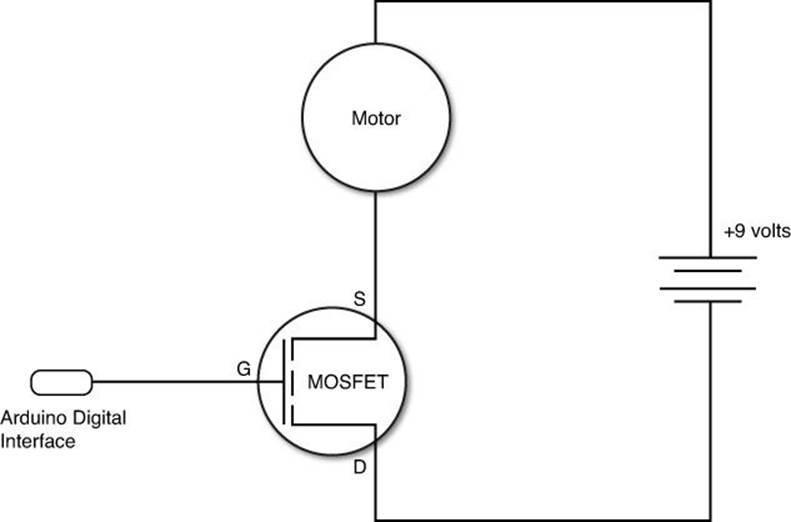
FIGURE 19.1 Using a transistor to control a motor circuit from your Arduino.
The key to selecting the right transistor to use is to ensure that the voltage and current rating can support the motor circuit. For most motor circuits that require extra current, the metal-oxide-semiconductor field-effect transistor (MOSFET) is the popular transistor to use. The MOSFET device is designed to handle higher voltages and currents, but still can be controlled by a small gate voltage. This is perfect for our Arduino projects.
To control the transistor from your Arduino sketch, all you need to do is connect a digital interface to the gate on the transistor. When you set the digital interface to HIGH, the transistor will allow current to flow through the circuit to the motor. When you set the digital interface to LOW, the transistor will block current in the motor circuit.
By The Way: Isolating the Arduino Pins
For very high-current motor circuits, it’s recommended to place a resistor between the Arduino digital interface pin and the transistor gate lead. That way, if the transistor should short out, the Arduino is protected from the high current. For small DC motors, this isn’t necessary.
Controlling Motor Speed
When the transistor is turned on by applying a voltage to the gate lead, the full power from the motor power source is applied to the motor, making it spin at a constant speed, based on the power source voltage.
If you remember from Hour 15, “Interfacing with Analog Devices,” the Arduino supports a special type of digital output called a pulse-width modulation (PWM) signal. The PWM turns the digital output on and off at a predefined interval, called the duty cycle. You can use the PWM duty cycle to control the speed of your motor.
By applying a PWM to the gate of the transistor device, you can control how fast the transistor gate opens and closes, which in turn controls how fast voltage is applied to and removed from the motor. The on and off duty cycle happens so fast that the motor appears to be running at a slower constant speed. By simply changing the duty cycle of the PWM signal, you can change the speed of the motor.
In your Arduino sketches, you create a PWM output on a digital interface pin by using the analogWrite function:
analogWrite(pin, dutycycle);
A dutycycle value of 0 will stop the motor, and a dutycycle value of 255 will operate the motor at full speed. Any value in between will operate the motor at a slower speed.
Controlling Motor Direction
Using PWM solves the speed problem when working with motors, but it doesn’t solve the direction problem. The motor turns in only one direction, depending on the polarity of the voltage applied to the motor leads. It would be somewhat cumbersome to physically change the wires going to a motor to get it to change directions.
There is, however, a fancy way to solve this problem, called an H-bridge. The H-bridge is a series of transistors interconnected so that the polarity of the voltage flow changes based on two control signals sent to the circuit. So, by using an H-bridge, you can control the motor direction by setting the digital state of the two control signals to determine which direction the motor operates, as shown in Table 19.1.
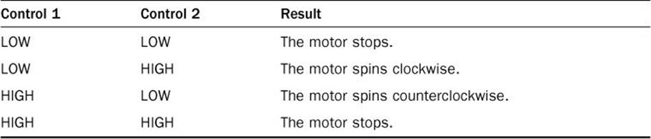
TABLE 19.1 H-Bridge Control Values
The H-bridge circuit is extremely popular in motor use, and because of that, there are plenty of pre-built H-bridge circuits you can buy. Most H-bridges come in integrated circuit (IC) format, so they’re easy to work with in your circuits. The Arduino Starter Kit includes an L293D H-bridge IC, which is ideal for most low-powered DC motors.
You control the H-bridge from your sketches by using three digital pins on the Arduino: one to turn the motor on and off, and two to control the motor direction. Your sketch just needs to keep track of which H-bridge control pin is connected to which digital interface pin.
Experimenting with Motors
Now that you’ve seen the basics of using DC motors with the Arduino, let’s build some circuits to test them. This section walks through two exercises for working with DC motors.
Turning a Motor On and Off
For this experiment, you use a switch connected to the Arduino to control when a motor runs or stops. The hardware part of the circuit is a little involved, so let’s go through that first. For the exercise, you need these parts:
![]() A low-current DC motor, found in most electronic supply stores
A low-current DC motor, found in most electronic supply stores
![]() A 9-volt battery clip with leads (along with a 9V battery)
A 9-volt battery clip with leads (along with a 9V battery)
![]() An NPN transistor, either a standard transistor (such as type TIP120) or a MOSFET transistor (such as type IRF510) will work for this project
An NPN transistor, either a standard transistor (such as type TIP120) or a MOSFET transistor (such as type IRF510) will work for this project
![]() A general-purpose power diode
A general-purpose power diode
![]() A momentary contact switch
A momentary contact switch
![]() A 1K-ohm resistor
A 1K-ohm resistor
![]() A 1-microfarad capacitor
A 1-microfarad capacitor
![]() A breadboard
A breadboard
Figure 19.2 shows the circuit that you’ll create for this exercise.
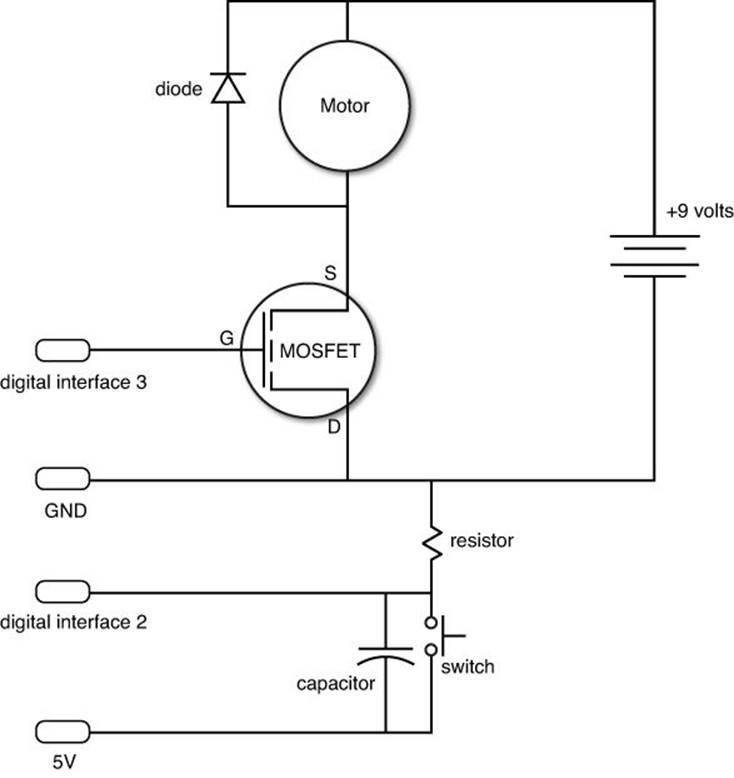
FIGURE 19.2 The DC motor circuit used for this exercise.
Here are the steps to follow to build the circuit:
1. Connect a jumper wire from the 5V pin on the Arduino to a rail on the breadboard.
2. Connect a jumper wire from the GND pin on the Arduino to another rail on the breadboard.
3. Connect the positive lead of the 9V battery clip to a third rail on the breadboard.
4. Connect the ground lead of the 9V battery clip to the same rail as the GND pin from the Arduino.
5. Place the momentary contact switch in the breadboard so that it straddles the middle of the breadboard and so that the contacts are connected to separate rails.
6. Connect the 1K-ohm resistor from one switch lead to the GND rail.
7. Connect the other switch lead to the 5V rail using a jumper wire.
8. Connect a jumper wire from the switch lead that’s connected to the resistor to the Arduino digital interface 2 pin.
9. Connect the capacitor across both leads of the switch.
10. Place the transistor in the breadboard so that each lead connects to a separate rail and so that the flat side (or the side away from the heat sink on a MOSFET transistor) is on the left.
11. Connect a jumper wire from the top MOSFET transistor lead to the digital interface 3 pin on the Arduino. This is the gate lead. For standard transistors, the gate lead is the middle lead.
12. Connect the bottom transistor lead to the GND rail. This is the source lead, and is the same for both MOSFET and standard transistors.
13. Connect one lead from the motor to the middle lead of the MOSFET transistor. This is the drain lead. For standard transistors, this is the top lead.
14. Connect the other lead from the motor to the 9V rail on the breadboard (the positive pole of the battery clip).
15. Place the diode so that the cathode lead (the end marked with the line) is on the 9V rail on the breadboard and the anode lead connects to the middle pin of the MOSFET transistor, or the top lead of a standard transistor.
The motor runs from the nine-volt battery. The diode is used to prevent back voltage generated by the motor from entering the circuit and burning out the transistor or the battery. The capacitor is added to help prevent switch bounce.
After you’ve built the circuit, you’re ready to start coding the Arduino sketch. Follow these steps:
1. Open the Arduino IDE, and enter this code into the editor window:
int switchPin = 2;
int motorPin = 3;
int led = 13;
int switchState = 0;
void setup() {
pinMode(motorPin, OUTPUT);
pinMode(led, OUTPUT);
digitalWrite(motorPin, LOW);
digitalWrite(led, LOW);
attachInterrupt(0, changeMotor, RISING);
}
void loop() {
}
void changeMotor() {
if (switchState == HIGH) {
digitalWrite(motorPin, LOW);
digitalWrite(led, LOW);
switchState = LOW;
} else {
digitalWrite(motorPin, HIGH);
digitalWrite(led, HIGH);
switchState = HIGH;
}
}
2. Save the sketch as sketch1901.
3. Click the Upload icon to verify, compile, and upload the sketch to your Arduino unit.
The sketch uses an external interrupt (see Hour 16, “Adding Interrupts”) triggered by the switch to determine when power is applied to the transistor gate or not. I also used the pin 13 LED built in to the Arduino to indicate when the circuit should be on or off. That way you can troubleshoot things if the motor doesn’t run.
Controlling Motor Speed
This exercise uses the exact same circuit as the previous exercise, but controls the transistor gate using a PWM generated on digital pin 3 of the Arduino. This enables you to control the speed of the motor by changing the duty cycle of the PWM output signal.
![]() Try It Yourself: Using PWM to Control a Motor
Try It Yourself: Using PWM to Control a Motor
To control the motor speed this exercise uses the same external interrupt triggered by the switch to enable one of four speed settings for the motor. Each time you press the switch, the speed will change to a higher value, and then the motor will stop on the fourth switch press.
Here are the steps to create the sketch:
1. Open the Arduino IDE, and enter this code into the editor window:
int switchPin = 2;
int motorPin = 3;
int switchState = 0;
void setup() {
analogWrite(motorPin, 0);
pinMode(13, OUTPUT);
digitalWrite(13, LOW);
attachInterrupt(0, changeMotor, RISING);
}
void loop() {
}
void changeMotor() {
switch(switchState) {
case 0:
analogWrite(motorPin, 75);
digitalWrite(13, HIGH);
break;
case 1:
analogWrite(motorPin, 150);
digitalWrite(13, LOW);
break;
case 2:
analogWrite(motorPin, 255);
digitalWrite(13, HIGH);
break;
case 3:
analogWrite(motorPin, 0);
digitalWrite(13, LOW);
}
switchState++;
if (switchState == 4)
switchState = 0;
}
2. Save the sketch as sketch1902.
3. Click the Upload icon to verify, compile, and upload the sketch to your Arduino unit.
4. Press the switch once; the motor should start at a slow speed, and the pin 13 LED on the Arduino board should light.
5. Press the switch a second time; the motor should go a bit faster, and the pin 13 LED should go out.
6. Press the switch a third time; the motor should go at full speed, and the pin 13 LED should light.
7. Press the switch a fourth time; the motor should stop, and the pin 13 LED should go out.
Notice in the changeMotor() interrupt function that for each switch, press the duty cycle used in the analogWrite() function changes. This is what causes the motor to spin at a different speed. At duty cycle 0, the motor stops.
Using Servo Motors
Controlling servo motors is a bit trickier than working with DC motors. The servo motor controller requires specialized signals to position the motor shaft. Fortunately for us, the Arduino developers have created a prebuilt library that makes working with servo motors a breeze. This section discusses the Servo library, and then demonstrates how to use it in your Arduino sketches.
The Servo Library
The Servo library is installed by default in the Arduino IDE package. To use the functions in the Servo library, you must first create a Servo object variable in your sketch:
Servo myServer;
After you create the Servo object, you use the Servo library functions to connect the object to a pin on the Arduino and send signals to the servo motor. Table 19.2 lists the functions available inside the library.
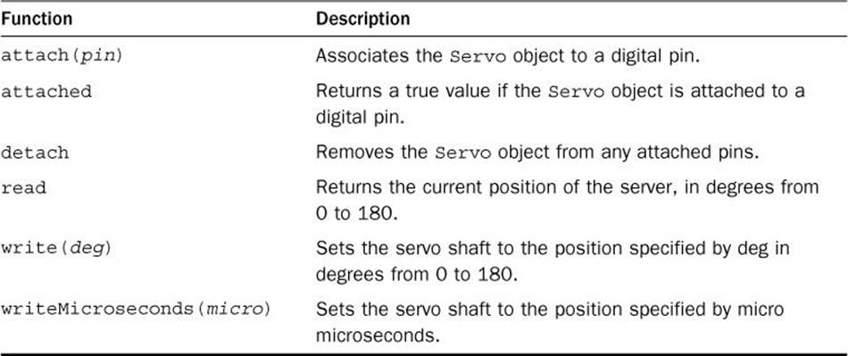
TABLE 19.2 The Servo Library Functions
Because servo motors operate as stepper motors, you can control the position of the motor shaft by either specifying a degree in the rotation (from 0 to 180 degrees) or as the number of microseconds the motor should step the shaft. For most applications, just specifying the degree value is sufficient; for fine-tuning to an exact location, however, you can use the microseconds value.
Typically, to work with the servo in your sketch, you just use three statements:
Servo myServo;
myServo.attach(5);
myServo.write(90);
The first statement creates the Servo object, the second statement attaches the object to digital interface pin 5, and then the third statement tells the servo to rotate the motor shaft to the 90-degree position.
Experimenting with Servos
This experiment allows you to control the position of a servo motor using a potentiometer. As you change the potentiometer position, the shaft of the servo motor turns to a new position.
![]() Try It Yourself: Positioning a Servo Motor
Try It Yourself: Positioning a Servo Motor
The Servo library in the Arduino IDE provides functions to control the position of a servo motor by specifying a degree value. The servo motor can position the motor shaft along a 180-degree arc.
Fortunately, the circuit for this exercise isn’t as complex as the previous one. All you need for this circuit are the following:
![]() A low-power servo motor
A low-power servo motor
![]() A 10K-ohm potentiometer
A 10K-ohm potentiometer
![]() An 100-microfarad electrolytic capacitor
An 100-microfarad electrolytic capacitor
![]() A breadboard
A breadboard
Most hobbyist servo motors are low powered, so you should be able to find one that operates within the 5V power of the Arduino at any electronic parts distributor. Also, because the servo motor runs on 5 volts, you don’t have to worry about using an external power source.
This exercise also uses a potentiometer to control the servo motor position. You’ll link the analog input from the potentiometer to the server output so rotating the potentiometer shaft rotates the servo motor. The electrolytic capacitor is used to help prevent any voltage spikes that may occur when the servo motor starts from damaging the potentiometer or the Arduino.
Here are the steps for building the circuit required for the exercise:
1. Connect the 5V pin on the Arduino to a rail on the breadboard using a jumper wire.
2. Connect the GND pin on the Arduino to a rail on the breadboard using a jumper wire.
3. Connect three jumper wires to the servo motor connector.
4. Connect the jumper wire from the black servo motor lead to the GND rail on the breadboard.
5. Connect the jumper wire from the red servo motor lead to the 5V rail on the breadboard.
6. Connect the jumper wire from the white servo motor lead to the digital interface 5 pin on the Arduino. This is the servo control interface.
7. Place the capacitor so that the positive lead is connected to the 5V rail and so that the other lead is connected to the GND rail.
8. Place the potentiometer on the breadboard so that the three leads are connected to separate rails.
9. Connect one outer lead from the potentiometer to the 5V rail on the breadboard.
10. Connect the other outer lead from the potentiometer to the GND rail on the breadboard.
11. Connect the middle lead from the potentiometer to analog interface 0 on the Arduino.
That completes the circuit. Figure 19.3 shows a diagram of the completed circuit.
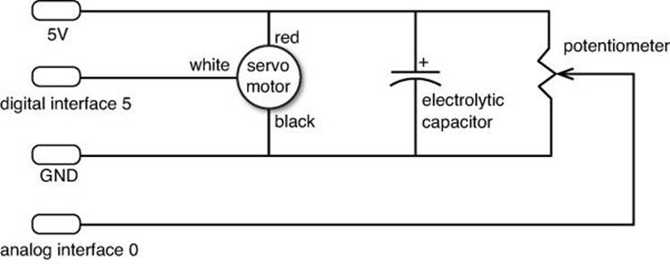
FIGURE 19.3 The servo motor circuit.
Now for coding the sketch. This exercise uses the Servo library that’s installed in the Arduino IDE by default, so follow these steps to use it:
1. Open the Arduino IDE, select Sketch from the menu bar, and then select Import Library, Servo.
2. Enter this code in the editor window:
#include <Servo.h>
Servo myServo;
int position;
void setup() {
myServo.attach(5);
}
void loop() {
position = analogRead(0);
position = map(position, 0, 1023, 179, 0);
myServo.write(position);
delay(10);
}
3. Save the sketch as sketch1903.
4. Click the Upload icon to verify, compile, and upload the sketch to your Arduino unit.
5. When the sketch starts to run, slowly turn the potentiometer shaft. The servo motor should move as you turn the shaft.
The sketch uses the map function to map the 1024-value range generated by the analogRead function into a 180-value range used to position the servo motor. Notice that I had to reverse the mapping to get my Arduino to move the servo shaft in the same direction that I moved the potentiometer shaft. Depending on how you connect your potentiometer, you may have to reverse that mapping in your setup.
By The Way: The Motor Shield
If you do a lot of work with motors, you may be interested in exploring the Arduino Motor Shield. The Motor Shield provides a standard interface for connecting up to two DC brushed motors and one servo motor. It also provides feedback on the current and voltage used by the motors in the circuit.
Summary
This hour explored the world of motors. Many applications require motors to move mechanical parts, from building robots to automating signs. You can use your Arduino to control both simple DC motors as well as more complicated stepping and servo motors. You can control the speed of a DC motor by using the PWM feature available on some of the digital interface ports. To control the direction of a motor, you need to use an external H-bridge and control it with two digital interface ports. For using servo motors, you need to use the Servo library, installed by default in the Arduino IDE. You can control the exact location of the servo motor shaft using simply commands within the Servo library.
In the next hour, you’ll learn another popular use of the Arduino: controlling LCD displays. Often, you need a quick interface to see the status or change the settings in a sketch, and connecting your Arduino to a computer using the serial monitor may not be an option. By adding a simple LCD to your Arduino, you can easily display short messages.
Workshop
Quiz
1. What type of motor should you use to precisely position a model airplane wing without error?
A. Servo motor
B. Stepper motor
C. DC motor
D. AC motor
2. Can you reverse the direction of a DC motor without having to physically reconnect it to the circuit? Yes or no.
3. What type of signal do you need to use to control the speed of a motor?
Answers
1. A. The servo motor includes circuitry to precisely control the location of the motor shaft.
2. Yes, you can use an H-bridge circuit to control the motor direction using two control signals.
3. By applying a pulse-width modulator (PWM) signal to the transistor gate, you can control the speed of the motor.
Q&A
Q. Can you control more than one servo motor from the same Arduino unit?
A. Yes, you can define multiple Servo objects in your sketch and attach each one to a separate digital interface pin.
Q. Does the Arduino contain a library for working with stepper motors?
A. Yes, you can use the Stepper library. It’s included in the Arduino IDE package by default.
All materials on the site are licensed Creative Commons Attribution-Sharealike 3.0 Unported CC BY-SA 3.0 & GNU Free Documentation License (GFDL)
If you are the copyright holder of any material contained on our site and intend to remove it, please contact our site administrator for approval.
© 2016-2026 All site design rights belong to S.Y.A.