Sams Teach Yourself Arduino Programming in 24 Hours (2015)
Part III: Arduino Applications
Hour 20. Using an LCD
What You’ll Learn in This Hour:
![]() The different types of LCD devices
The different types of LCD devices
![]() How to use an LCD with your Arduino
How to use an LCD with your Arduino
![]() How to use the LCD shield
How to use the LCD shield
So far in our experiments, we’ve used the serial monitor output on the Arduino to communicate information from our sketches. That’s an easy way of communicating, but it does limit the use of the Arduino because you must have a computer connected to display the information. You can, however, display data from your Arduino in other ways without using a computer. One of the most popular methods is to use LCD devices. This hour demonstrates how to use LCD devices in your Arduino projects to output data from your sketches.
What Is an LCD?
Liquid crystal display (LCD) devices have been used by electronic devices for years to display simple alphanumeric information. The principle behind the LCD is to energize a series of crystals contained within a sealed enclosure to appear either opaque or transparent against a lighted background. The crystals are arranged in a pattern so that you can produce letters, numbers, and symbols based on which crystals are opaque and which ones are transparent.
Many different types of LCD devices are on the market. This section discusses some of the features that you need to be aware of as you look for LCD devices to use in your Arduino projects.
Display Types
You can use two basic types of LCD devices in your Arduino projects:
![]() Alphanumeric LCD devices
Alphanumeric LCD devices
![]() Graphical LCD devices
Graphical LCD devices
An alphanumeric LCD device uses a small grid of lights to display letters, numbers, and simple symbols. The most common grid layout is a 5 × 8 grid of dots. The LCD displays each character by turning on or off each crystal in the grid to represent the character, as shown in Figure 20.1.
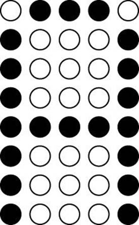
FIGURE 20.1 The 5 × 8 LCD grid layout displaying the letter A.
Alphanumeric LCD devices commonly include several character grids arranged in a line so that you can display words and sentences. The most common alphanumeric LCD devices used in the Arduino world is the 16 × 2 LCD device, which can display two lines of 16 characters.
Graphical LCD devices use a single larger grid of individual lights to display information. Instead of a separate grid for each character, graphical LCD devices provide a single array of crystal dots that you must control individually.
The most common graphical grid layout that you’ll find for Arduino projects is the 128 × 64 LCD. The benefit of that layout is that you can display characters at any resolution you prefer; you’re not limited to the 5 × 8 resolution used in alphanumeric LCD devices. Also, you can use the 128 × 64 layout as a canvas, creating complex drawings as well as numbers and letters.
Color Types
Besides the display type of the LCD device, you can also use different color patterns to display the characters. The LCD device uses two light sources. One light source is the color of the LCD crystals, and the other color is the background light that the crystals block. This produces two different ways to color the LCD:
![]() A negative LCD displays characters in color on a dark background.
A negative LCD displays characters in color on a dark background.
![]() A positive LCD displays dark characters on a color background.
A positive LCD displays dark characters on a color background.
With the negative display type, you often have a choice of which color the characters appear in. However, you only have one color choice per LCD device.
With a positive LCD, small LEDs are used to light the background, so there are often more color choices. Another advantage of using a positive LCD is the RGB type of background; it provides three background LEDs: red, green, and blue. You can adjust the intensity of each background light to produce just about any background color.
Interfacing with LCD Devices
As you might guess, there are lots of individual dots to turn on and off in an LCD device to produce output. Just trying to display a simple 16-letter sentence requires having to control 5 × 8 × 16 = 640 separate dots.
Fortunately for us, we don’t have to worry about trying to turn individual dots on or off to display characters. Most LCD devices used in Arduino projects include a separate controller chip that interfaces with the LCD. That helps reduce the number of wires we need to use to control the LCD, and makes it easier to send signals to display characters. This section discusses how to use these types of LCD devices with your Arduino.
LCD Device Wiring
The most popular LCD devices that you’ll find for Arduino projects use the HD44780 controller chip to manage the LCD. That chip uses a series of 16 interface pins, shown in Table 20.1.
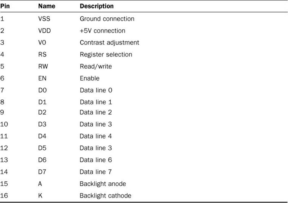
TABLE 20.1 The HD44780 Interface Pins
The 16 interface pins are usually located in the upper-left side of the LCD device. Figure 20.2 shows an example of an LCD device that uses an HD44780 controller chip.
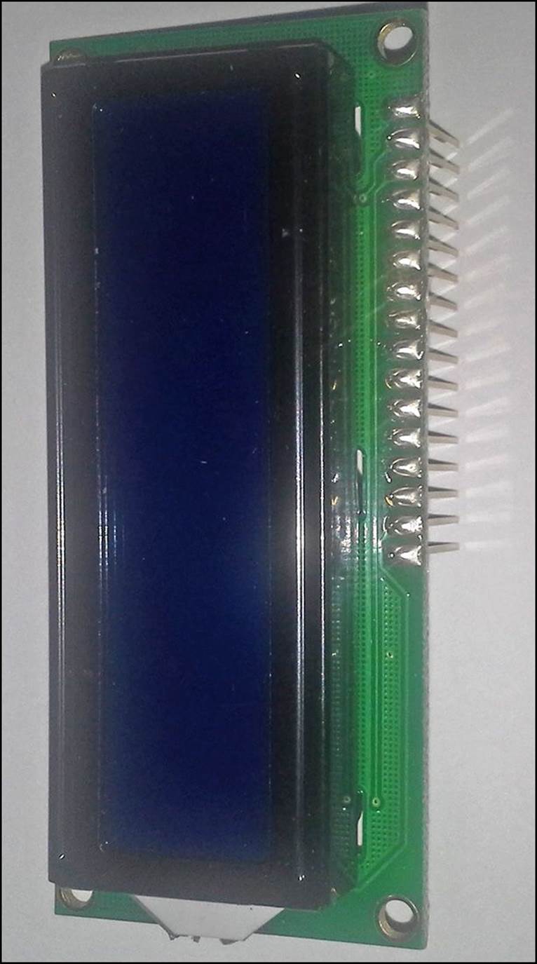
FIGURE 20.2 A monochrome LCD device using the HD44780 chip.
The LCD uses long header pins that easily plug into a breadboard, or that can be soldered into a printed circuit board. All you need to do is connect the LCD pins to your Arduino digital interface pins.
However, you don’t need to dedicate 16 pins on your Arduino to communicate with the HD44780 chip. The really neat thing about the HD44780 LCD controller chip is that it can operate in two modes: 8-bit mode or 4-bit mode.
In 4-bit mode, you need to use only four data lines to send the character data, which saves on the number of wires you need to interface from your Arduino to the chip. All you need is six wires—data lines 4 through 7, the EN line, and the RS line.
By The Way: Multicolor Backlighting
The LCD kits that support multicolor backlights have 18 interface pins rather than 16. Pins 16, 17, and 18 control the red, green, and blue LEDs for the backlight color. You can control the LCD background color by sending pulse-width modulation (PWM) signals to each of those three pins.
Connecting the LCD to Your Arduino
One of the more complicated parts of using an LCD device is getting it wired to your Arduino. The first part of the process is deciding just what Arduino digital interfaces you have available to use to control the LCD. Remember, you need at least six digital interfaces, which decreases the number of interfaces you have available for working with sensors.
You must keep track of which digital interfaces you use for which LCD signal for your sketches. The easiest way to do that is to create a table that maps the digital interface ports you select to the LCD pins. Table 20.2 shows the map used for the examples in this hour.
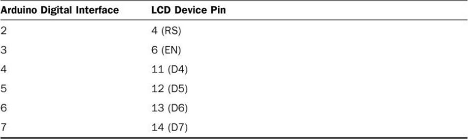
TABLE 20.2 Mapping Arduino Interfaces to the LCD
Besides these pins, you also need to connect six more pins on the LCD device:
![]() Pin 1 connects to ground (GND).
Pin 1 connects to ground (GND).
![]() Pin 2 connects to +5 volts.
Pin 2 connects to +5 volts.
![]() Pin 3 connects to +5 volts, but through a potentiometer.
Pin 3 connects to +5 volts, but through a potentiometer.
![]() Pin 5 connects to ground (GND).
Pin 5 connects to ground (GND).
![]() Pin 15 connects to +5 volts through a resistor.
Pin 15 connects to +5 volts through a resistor.
![]() Pin 16 connects to ground.
Pin 16 connects to ground.
Pins 1 and 2 provide power to the LCD device, and pins 15 and 16 power the LED backlight. Depending on the LCD device, you may or may not have to use a resistor to connect pin 15 to the +5 volts. Most LED backlights don’t require the resistor, but some do. If in doubt, go ahead and use a small resistor, such as 220 ohms to help limit the current going to the LED backlight.
If you’re using an RGB backlight LCD, you must connect pins 16, 17, and 18 to create the color background you want. You can connect these to PWM pins on the Arduino to vary the voltage applied to each; those signals control what color appears in the background.
Pin 3 controls the contrast of the LCD characters. You can place a potentiometer between pin 3 and the +5V so that you can adjust how bright the display appears. The size of the potentiometer doesn’t matter, but the larger the value the less sensitive the contrast control will be.
Figure 20.3 shows the completed schematic for wiring the LCD to your Arduino.
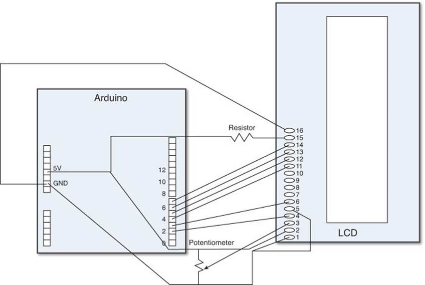
FIGURE 20.3 The Arduino LCD wire schematic.
After you’ve mapped out what pins you need to connect, place the LCD connectors in a breadboard, and use jumper wires to connect them to the proper place. It helps to connect the Arduino +5 and GND pins to rails on the breadboard to make it easier to connect the various LCD pins that require power or ground.
Once you have the LCD device wired to your Arduino, you’re ready to start programming your sketches.
The LiquidCrystal Library
By now, you should expect that the resourceful developers that are part of the Arduino community would have created a custom library for working with LCD devices—and you’d be correct! The LiquidCrystal library, which is installed by default in the Arduino IDE package, makes it a snap to interface with LCD devices from your sketches.
The LiquidCrystal Functions
The LiquidCrystal library defines a series of functions that you use to output data to the LCD. Table 20.3 describes these functions.
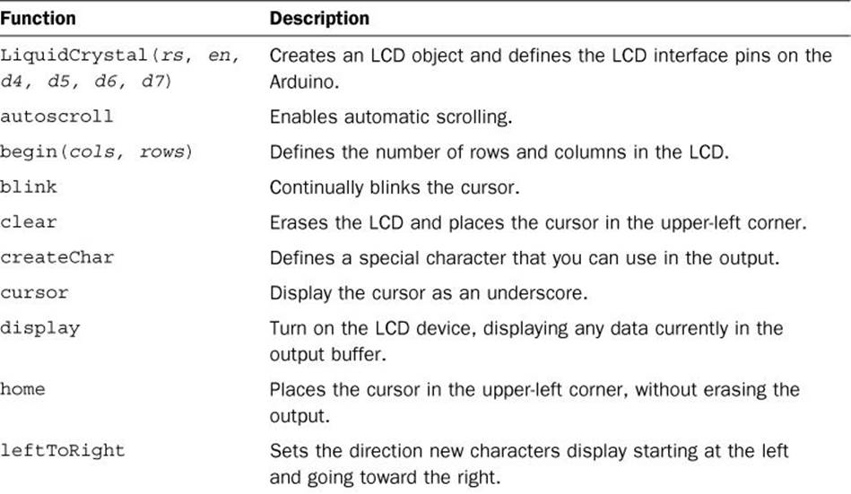
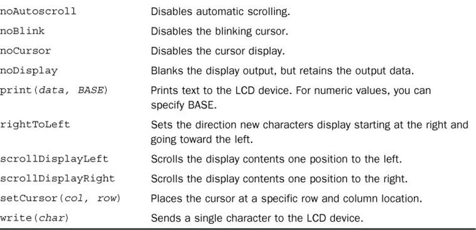
TABLE 20.3 The LiquidCrystal Library Functions
The LiquidCrystal function is a little odd in that it acts like an object-oriented object rather than a function. You define an object of the LiquidCrystal type, and then you can use the other library functions on that object. The next section walks through how to do that.
Using the Library
To use the LiquidCrystal library in your Arduino shield, you first must define a LiquidCrystal object:
LiquidCrystal lcd(2, 3, 4, 5, 6, 7);
The variable lcd becomes an object using the LiquidCrystal type. The parameters of the function define the Arduino digital interface pins that you connected to the LCD interface pins (RS, EN, D4, D5, D6, and D7). If you choose to use all eight data lines, the first four data lines can be specified first in the data line order (RS, EN, D0, D1, D2, D3, D4, D5, D6, D7).
After you create the LiquidCrystal object, you can use the library functions on that object:
lcd.begin(16, 2);
lcd.home();
lcd.print("This is a test");
lcd.setCursor(0, 2);
lcd.print("This is the end of the test");
The begin function defines the columns and rows available on the device. This sketch example uses a 16 × 2 LCD device to display two lines of 16 characters. The sketch uses the setCursor function to move the cursor to the second line in the LCD device before displaying the second line of text.
Watch Out!: Overflow
Notice in the second output line that I try to display more than 16 characters in the print function. On a 16 × 2 display, the output line is truncated after 16 characters. Some larger displays (such as 20 × 2) wrap the text to the next line in the device. Be careful that you know just how your specific LCD device operates before using it!
Using an LCD Device
Now that you’ve seen the basics of how to use an LCD device with your Arduino, let’s go through an example.
![]() Try It Yourself: Displaying Data
Try It Yourself: Displaying Data
This example uses an LCD device along with the LiquidCrystal library to display the temperature detected from a TMP36 sensor (see Hour 18, “Using Sensors”).
First, connect the LCD device to your Arduino as described earlier in the “Connecting the LCD to the Arduino” section. Then, follow these steps to connect the temperature sensor:
1. Plug the TMP36 sensor into the breadboard so that the three leads are connected to three separate rails. Make sure the flat side of the sensor is facing toward your left.
2. Connect the top pin of the TMP36 sensor to the +5V rail on your breadboard.
3. Connect the bottom pin of the TMP36 sensor to the ground rail on your breadboard.
4. Connect the middle pin of the TMP36 sensor to the Analog 0 interface on the Arduino.
Now that you have your circuit ready, you can create the sketch. Here are the steps to do that:
1. Open the Arduino IDE, and then click Sketch, Import Library, and then select the LiquidCrystal library.
2. In the editor window, enter this code:
#include <LiquidCrystal.h>
int output;
float voltage;
float tempC;
float tempF;
LiquidCrystal lcd(2, 3, 4, 5, 6, 7);
void setup() {
lcd.begin(16, 2);
lcd.home();
lcd.print("The temp is:");
}
void loop() {
output = analogRead(A0);
voltage = output * (5000.0 / 1024.0);
tempC = (voltage - 500) / 10;
tempF = (tempC * 9.0 / 5.0) + 32.0;
lcd.setCursor(5, 2);
lcd.print(int(tempF));
delay(5000);
}
3. Save the sketch as sketch2001.
4. Click the Upload icon to verify, compile, and upload the sketch to your Arduino unit.
As soon as the sketch completes the upload process, your Arduino should display the temperature in the LCD device. If you have an alternative power source for your Arduino, disconnect the USB cable from the Arduino and plug in the alternative power source. Your Arduino should power on and then display the temperature. Try holding the TMP36 sensor to make the temperature rise, or try placing an ice cube in a plastic bag next to the sensor to make the temperature fall. The LCD display should display the updated temperature after the 5-second delay. The delay is necessary; otherwise, the LCD output would be continually changing.
By The Way: Using the Contrast
Don’t get too discouraged if you plug everything in and nothing appears on the LCD. Play around with the contrast potentiometer connected to pin 3 on the LCD device. You may have to turn it all the way to the end of the rotation before anything appears in the display.
The LCD Shield
Yet another help is the LCD shield for the Arduino. Created by the popular Adafruit electronics company, it combines a 16 × 2 LCD device with a series of buttons that plugs into the standard Arduino Uno shield format. Figure 20.4 shows the LCD shield.
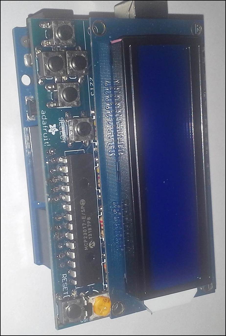
FIGURE 20.4 The Arduino LCD shield.
The LCD shield includes six buttons. Four buttons along the left side of the shield are arranged to provide an up, down, left, and right interface for simple menu control. A fifth button is set to the side of those buttons to act as a selection button, and the sixth button is on the right side of the shield and interfaces with the Reset pin on the Arduino (because you can’t reach the Arduino reset button with the shield installed). Also on the shield is a potentiometer for adjusting the brightness of the LCD.
The nice thing about the LCD shield is that instead of using six connections, it only uses three pins to interface with the Arduino. It does that by utilizing the I2C interface (see Hour 17, “Communicating with Devices”).
The Arduino sends data using the I2C protocol to the chip on the LCD shield, which decodes the signals and converts them to drive the HD44780 controller chip.
This section walks through installing the LCD shield library and using it in a sketch to display data on the LCD shield.
Downloading and Installing the Library
The LCD shield comes complete with its own library. The LCD shield library replicates all of the features of the standard LiquidCrystal library, plus adds a couple of customized functions specific to the shield.
To download and install the LCD shield library into your Arduino IDE environment, follow these steps:
1. Read the instructions for downloading and installing the LCD shield library on the Adafruit website:
https://learn.adafruit.com/rgb-lcd-shield/using-the-rgb-lcd-shield
2. Click the link to download the Adafruit RGB LCD shield library. This will download the folder Adafruit-RGB-LCD-Shield-Library-master.
3. Copy the Adafruit-RGB-LCD-Shield-Library-master folder to your Arduino libraries folder, usually located under the Documents folder for your Windows or OS X user account.
4. Rename the folder to LCDShieldLibrary.
Now when you look in the Import Library feature in the Arduino IDE, you should see the LCDShieldLibrary listed in the Contributed section. If so, you’re ready to start using it.
The LCD Shield Library Functions
The LCD shield library uses the same format as the LiquidCrystal library, including all the same function names. That makes migrating your application from a standard LCD device to the LCD shield a breeze.
The only difference is in the initial object that you create. Instead of a LiquidCrystal object, you use the following:
Adafruit_RGBLCDShield lcd = Adafruit_RGBLCDShield();
After you define the object, you can use the same features as the standard LiquidCrystal library:
lcd.begin(16,2);
lcd.setCursor(0,1);
lcd.print("This is a test");
The LCD shield library adds two new functions of its own:
![]() setBacklightColor: Sets the background color of RGB LCD devices using standard color names.
setBacklightColor: Sets the background color of RGB LCD devices using standard color names.
![]() readButtons: Retrieves the status of all the buttons on the LCD shield.
readButtons: Retrieves the status of all the buttons on the LCD shield.
The setBacklightColor function makes it easy to use RGB backlit LCD devices. You don’t have to worry about setting pin voltages on the LCD device; all you do is specify what color you want to use for the background in the setBacklightColor function. Currently, it recognizes the colors red, yellow, green, teal, blue, violet, and white.
The readButtons function allows you to detect button presses on the LCD shield. You can tell which button was selected by using a logical AND operation on the output of the readButton function, with the labels BUTTON_UP, BUTTON_DOWN, BUTTON_RIGHT, BUTTON_LEFT, and BUTTON_SELECT:
button = lcd.readButtons();
if (button & BUTTON_UP) {
lcd.print("The UP button");
else if (button & BUTTON_DOWN) {
lcd.print("The DOWN button");
}
By The Way: Switch Bounce
The readButtons function in the LCD shield library uses code to eliminate switch bounce, so there’s no need for you to add that yourself in your code.
Connecting the LCD Shield
The easiest way to use the LCD shield is to plug it directly into your Arduino. The pin layout of the LCD shield is designed to fit exactly into the standard Arduino Uno pin layout.
However, if you do that, you won’t have access to any of the interface pins on the Arduino. You have two options to solve that problem:
![]() One option is to use a separate prototype board plugged between the Arduino and the LCD shield. Hour 24, “Prototyping Projects,” shows how to do that. From the prototype shield, you can pull out the pins necessary to connect the sensor, such as the analog interface pin, and the +5V and GND pins for powering the sensor.
One option is to use a separate prototype board plugged between the Arduino and the LCD shield. Hour 24, “Prototyping Projects,” shows how to do that. From the prototype shield, you can pull out the pins necessary to connect the sensor, such as the analog interface pin, and the +5V and GND pins for powering the sensor.
![]() The other method is to remotely connect the LCD shield board to the Arduino. Because the LCD shield uses the two I2C pins to communicate with the Arduino, you only need to connect four wires (the two I2C pins, the ground pin, and the +5V pin) between the LCD shield and the Arduino. Figure 20.5 demonstrates this.
The other method is to remotely connect the LCD shield board to the Arduino. Because the LCD shield uses the two I2C pins to communicate with the Arduino, you only need to connect four wires (the two I2C pins, the ground pin, and the +5V pin) between the LCD shield and the Arduino. Figure 20.5 demonstrates this.
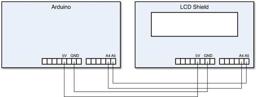
FIGURE 20.5 Connecting the LCD shield remotely to the Arduino Uno.
The I2C pins are located in different places on the different Arduino models. The Uno uses analog interface 4 and 5, the Mega uses digital interface pins 20 and 21, and the Leonardo uses digital interface pins 2 and 3. The nice thing about using an Arduino Uno is that all the pins you need are in the bottom interface of the LCD shield. That way you don’t have to plug the entire shield into your breadboard.
Watch Out!: The Ground Pin
Be careful when connecting the GND pin on the LCD shield device. The GND pin next to the 5V pin is not connected; you must use the GND pin that’s next to the Vin pin.
After you connect the LCD shield, you’re ready to start coding. The next section walks through an updated temperature sensor example.
Using the LCD Shield
Let’s update the temperature sensor example that we worked on earlier using the LCD shield. Make sure that you have your LCD shield connected as shown in the “Connecting the LCD Shield” section, and then work through this example.
![]() Try It Yourself: Displaying Data Using the LCD Shield
Try It Yourself: Displaying Data Using the LCD Shield
In this example, not only do you use the LCD shield to display the temperature, but you also use two of the buttons on the shield to toggle between displaying the temperature in Celsius and Fahrenheit.
You’ll use the same TMP36 sensor, connected to analog interface 0, as you did before.
To create the sketch for the example, follow these steps:
1. Open the Arduino IDE, and select the Sketch menu option to import the LCDShieldLibrary library.
2. In the editor window, add a line before the two #include lines:
#include <Wire.h>
The LCD shield library uses some special data types that require the Wire.h library, but unfortunately at the time of this writing, the library doesn’t automatically include that library file, so you need to manually type it into the code.
3. In the editor window, add this code:
#include <Wire.h>
#include <Adafruit_MCP23017.h>
#include <Adafruit_RGBLCDShield.h>
int output;
char temp[] = "C";
float voltage;
float tempC;
float tempF;
Adafruit_RGBLCDShield lcd = Adafruit_RGBLCDShield();
void setup() {
lcd.begin(16, 2);
lcd.home();
lcd.print("The temp is:");
}
void loop() {
output = analogRead(A0);
voltage = output * (5000.0 / 1024.0);
tempC = (voltage - 500) / 10;
tempF = (tempC * 9.0 / 5.0) + 32.0;
lcd.setCursor(5, 1);
uint8_t button = lcd.readButtons();
if (button & BUTTON_UP) {
strcpy(temp, "C");
} else if (button & BUTTON_DOWN) {
strcpy(temp, "F");
}
if (strcmp(temp, "C")) {
lcd.print(int(tempC));
lcd.print(" C");
} else {
lcd.print(int(tempF));
lcd.print(" F");
}
}
4. Save the file as sketch2002.
5. Click the Upload icon to verify, compile, and upload the sketch to your Arduino unit.
When the sketch starts, it should show the temperature in Fahrenheit. Press the Down button on the LCD shield, and the output should change to show the temperature in Celsius. Press the Up button to change the temperature display to Fahrenheit.
Summary
This hour showed you how to use LCD devices in your Arduino projects. You can use a plain LCD device by connecting six wires from the Arduino to the LCD. The EN and RS lines must be connected to digital interfaces on the Arduino, along with four data lines D4, D5, D6, and D7. The LiquidCrystal library, which is installed by default in the Arduino IDE, provides an easy way to send data to the LCD device to display.
The hour also showed you how to use the popular LCD shield created by Adafruit. The LCD shield can either plug directly into the Arduino Uno interfaces or you can remotely connect it using a breadboard and jumper wires. You only need to connect four wires: the two I2C pins, the +5 pin, and the GND pin.
The next hour explores another popular shield used in Arduino projects: the Ethernet shield. The Ethernet shield provides an easy way to connect your Arduino to a network to both send and receive data with other network devices.
Workshop
Quiz
1. Which Arduino library do you use to interface with an LCD device?
A. The Wire library
B. The EEPROM library
C. The LiquidCrystal library
D. The SPI library
2. The LCD shield uses six wires to interface with the Arduino. True or false?
3. What LiquidCrystal library function do you use to move the cursor to the second line in the LCD device to display more data?
Answers
1. C. The Arduino IDE includes the LiquidCrystal library by default, which allows you to easily interface with standard LCD devices.
2. False. The LCD shield requires only two I2C connections (the +5V connection and a GND connection), totaling four wires.
3. The setCursor function allows us to specify the row and column location of the cursor. The output from the print or write functions will appear at the location of the cursor in the LCD device.
Q&A
Q. Can I use more than one LCD device on an Arduino at the same time?
A. Yes, it’s been done! Because you only need six connections to the LCD device, you can connect two separate LCD devices directly to your Arduino and create two separate LiquidCrystal objects, each one pointing to the appropriate digital interface lines.
Another option that some developers have used, though, is to share the four data lines and the RS line with multiple LCD devices. Each device then connects to a separate digital interface for the EN signal. The LCD device only reads the data lines when the EN signal is HIGH, so you can control which device receives the output data by controlling which EN signal is set HIGH.
All materials on the site are licensed Creative Commons Attribution-Sharealike 3.0 Unported CC BY-SA 3.0 & GNU Free Documentation License (GFDL)
If you are the copyright holder of any material contained on our site and intend to remove it, please contact our site administrator for approval.
© 2016-2026 All site design rights belong to S.Y.A.