Sams Teach Yourself Arduino Programming in 24 Hours (2015)
Part III: Arduino Applications
Hour 22. Advanced Network Programming
What You’ll Learn in This Hour:
![]() How to create a web server on your Arduino
How to create a web server on your Arduino
![]() Retrieving sensor data with a web browser
Retrieving sensor data with a web browser
![]() Controlling an Arduino from a web browser
Controlling an Arduino from a web browser
In the previous hour, you saw how to use the Ethernet Shield to communicate on an Ethernet network from your Arduino device. That opens a whole new world of ways for you to communicate with your Arduino projects. This hour expands on that by showing how to provide sensor data to remote clients by using the Arduino as a web server and also how to control your Arduino from a remote client.
The Web Protocol
Thanks to the World Wide Web, the Hypertext Transfer Protocol (HTTP) has become the most popular method of transferring data on networks. Web browser client software comes standard on just about every workstation, tablet, and smartphone device. You can leverage that popularity with your Arduino programs by incorporating web technology to interface with your sketches.
Before you can do that, though, you need to know a little bit about how HTTP works. This first section walks through the basics of an HTTP session, and shows how to transfer data using HTTP servers and clients.
HTTP Sessions
HTTP uses a client/server model for transferring data. One device acts as the server, listening for requests from clients. Each client establishes a connection to the server and makes a request for data, usually a data file formatted using the Hypertext Markup Language (HTML). If the request is successful, the server sends the requested data back to the client and closes the connection. Figure 22.1 demonstrates this process.
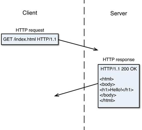
FIGURE 22.1 A typical HTTP session.
HTTP specifies how the client and server communicate with each other. The current standard for HTTP is version 1.1, and is defined by the World Wide Web Consortium (W3C). It specifies the exact format for each request and response message. The client makes a specially-formatted HTTP request to ask for the data, and the server responds with an HTTP response, along with the requested data.
The HTTP Request
The HTTP specifications define the client’s request to the server. Because HTTP is a text-oriented protocol, the client HTTP request consists of all text, separated into three parts:
![]() A request line
A request line
![]() Request header lines (optional)
Request header lines (optional)
![]() An empty line terminated by a carriage return-line feed combination
An empty line terminated by a carriage return-line feed combination
The combination of the request line and header lines tell the server just what data the client wants to retrieve, along with some information about the client. Let’s take a closer look at those parts.
The Request Line
The request line identifies the object the client is requesting from the server. It consists of three parts:
![]() A method token
A method token
![]() A Universal Resource Indicator (URI) identifying the requested data
A Universal Resource Indicator (URI) identifying the requested data
![]() The protocol version
The protocol version
The method token defines the method action performed on the specified URI. Table 22.1 lists the valid method tokens currently supported in HTTP 1.1.
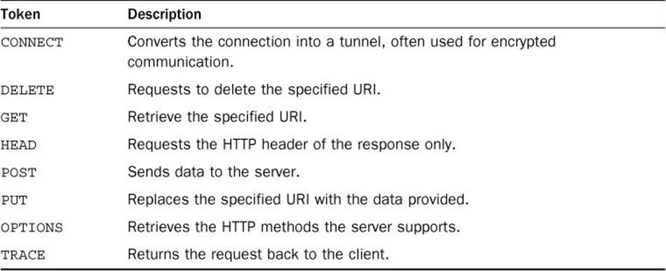
TABLE 22.1 HTTP Method Tokens
The GET and POST methods allow the client to send data to the server within the request. The GET method embeds the data with the URI itself, while the POST method sends the data as separate messages within the HTTP session.
The URI defines the path and filename of the data file you want to retrieve. The path is relative to the root folder of the web server.
The protocol version defines the HTTP version that the client is using.
A complete HTTP request looks something like this:
GET /index.html HTTP/1.1
This is the text the client sends to the web server to request the file index.html from the root folder of the web server.
Request Headers
After the request line, the client can optionally send one or more request headers. The request headers allow the client to send additional information about the request, about the connection, or even about the client itself (such as identifying the browser being used). The request header uses the following format:
header: value;
Each request header appears on a separate line and is terminated with a semicolon. The end of the request header list is indicated by an empty line with a carriage return and linefeed combination.
If your web client chooses to include request headers, a complete HTTP request would look something like this:
GET /index.html HTTP/1.1
User-Agent: Microsoft IE/10.0
Connection: Close
This request asks to retrieve the index.html file from the web server. It identifies the client web browser as the Internet Explorer package and tells the server to close the HTTP session connection after returning the response.
The HTTP Response
When the web server receives a request from a web client, it must formulate a response to return. The response consists of three parts:
![]() The status line
The status line
![]() One or more response header lines (optional)
One or more response header lines (optional)
![]() An empty line terminated by a carriage return-line feed combination
An empty line terminated by a carriage return-line feed combination
If the request is successful, the requested data follows immediately after the HTTP response. Just like the HTTP request, the HTTP response is a plain-text message. Let’s take a look at the different parts of the response.
The Status Line
The status line returns the status of the request to tell the client how the server handled it. The status consists of three parts:
version status-code description
The version returns the HTTP version the server is using (usually HTTP/1.1). The status code and description indicate the status of the request. The status code is a three-digit code that indicates the status of the client’s request. This allows the client to quickly identify success or failure of the request. If the request failed, the response code indicates a detailed reason why the request failed. There are five categories of HTTP status codes:
![]() 1xx: Informational messages
1xx: Informational messages
![]() 2xx: Success messages
2xx: Success messages
![]() 3xx: Redirection messages
3xx: Redirection messages
![]() 4xx: Client-side errors
4xx: Client-side errors
![]() 5xx: Server-side errors
5xx: Server-side errors
Table 22.2 shows the full list of response status codes available in HTTP 1.1.
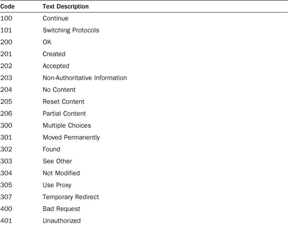
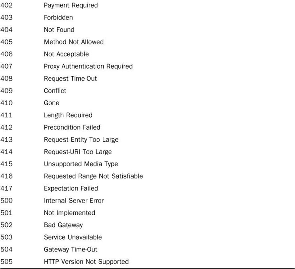
TABLE 22.2 HTTP Response Status Codes
The status-code numbers are always the same, but the text description may change depending on the server. Some servers provide more detail for failed requests.
The Response Header Lines
The response header lines allow the server to send additional information to the client besides the standard response code. The HTTP 1.1 version provides for lots of different response headers that you can use. Similar to request headers, response headers use the following format:
header: value;
Each response header is on a separate line and terminated with a semicolon. The end of the response header list is indicated by an empty line with a carriage return and linefeed combination.
A standard HTTP response would look something like this:
HTTP/1.1 200 OK
Host: myhost.com
Connection: Close
If any data is returned as part of the response, it should follow the closing carriage return and linefeed line of the header.
Now that you’ve seen how HTTP works, let’s take a look at using it in an Arduino sketch to communicate with client workstations.
Reading Sensor Data from a Web Server
Currently, there isn’t a standard Arduino library available for running a web server from your Arduino. Instead, you need to do a little coding to emulate the web server to remote clients. However, that’s not as hard as you might think, thanks to the simplicity of HTTP and the HTML web page markup language.
This section walks through building a web server that returns the output from a temperature sensor using the Arduino Ethernet library to serve your sensor data on the network.
Building the Circuit
For the circuit, you need to connect a temperature sensor to your Arduino to provide the temperature information. In Hour 18, “Using Sensors,” we worked with the TMP36 analog temperature sensor. The sensor provides an analog output signal that indicates the temperature. You just need to connect that output to an analog interface on the Arduino to process the data. Because the Ethernet Shield provides all the interface pins from the Arduino, you can plug your circuit directly into the Ethernet Shield interface header pins just as you would the regular Arduino interface header pins.
![]() Try It Yourself: Analog Temperature Sensor
Try It Yourself: Analog Temperature Sensor
To set up the analog temperature sensor for the web server project, follow these steps:
1. Place the TMP36 temperature sensor on the breadboard so that each of the three pins is in a separate rail row. Face the sensor so the flat edge is facing toward the left.
2. Plug the Ethernet Shield into the Arduino.
3. Connect the top pin of the TMP36 sensor to the +5 pin on the Ethernet Shield.
4. Connect the bottom pin of the TMP36 sensor to the GND pin on the Ethernet Shield.
5. Connect the middle pin of the TMP36 sensor to the analog interface 0 pin on the Ethernet Shield.
6. Plug a standard Ethernet network cable into the RJ-45 jack on the Ethernet Shield.
7. Plug the other end of the Ethernet network cable into your network switch or hub.
That’s all the hardware you need for this exercise. Next comes writing the sketch.
Writing the Sketch
To build the server, you need to use the Ethernet library, which is installed by default in the Arduino IDE package. However, when you select the Ethernet library from the IDE interface, it adds more #include directives than you need for the sketch code, which will needlessly increase the size of your sketch when loaded on to the Arduino. Instead, we’ll just manually add the #include directives to the code. Just follow these steps:
1. Open the Arduino IDE, and enter this code into the editor window:
#include <SPI.h>
#include <Ethernet.h>
byte mac[] = {0x90, 0xa2, 0xda, 0x0e, 0x98, 0x34};
EthernetServer server(80);
void setup() {
Serial.begin(9600);
Ethernet.begin(mac);
delay(1000);
Serial.print("The server is on IP address: ");
Serial.println(Ethernet.localIP());
}
void loop() {
EthernetClient client = server.available();
if (client.connected()) {
int temp = getTemp();
client.println("HTTP/1.1 200 OK");
client.println("Content-Type: text/html");
client.println("Connection: close");
client.println();
client.println("<!DOCTYPE HTML>");
client.println("<html>");
client.println("<head>");
client.println("<title>Current Temperature</title>");
client.println("</head>");
client.println("<body>");
client.println("<h1>The Current Temperature</h1>");
client.print("<h2>The current temperature is ");
client.print(temp);
client.println("° F</h2>");
if ((temp >= 68) && (temp <= 72))
client.println("<p>It's a normal room temperature</p>");
if (temp < 68)
client.println("<p>It's a little cold in here!</p>");
if (temp > 72)
client.println("<p>It's a little warm in here!</p>");
client.println("</body>");
client.println("</html>");
delay(10);
client.stop();
}
}
int getTemp() {
int output;
float voltage, tempC, tempF;
output = analogRead(A0);
voltage = output * (5000.0 / 1024.0);
tempC = (voltage - 500) / 10;
tempF = (tempC * 9.0 / 5.0) + 32.0;
return int(tempF);
}
2. Save the sketch as sketch2201.
3. Click the Upload icon to verify, compile, and upload the sketch to your Arduino unit. (Make sure that you have the USB cable connected to your Arduino.)
4. Open the serial monitor tool from the Arduino IDE toolbar.
5. Press the Reset button on the Ethernet Shield. This resets the Arduino, restarting the sketch from the beginning. When the sketch starts, you should see the IP address assigned to your Arduino from your network appear in the serial monitor window.
Now your Arduino should be waiting for clients to connect to retrieve the temperature from the sensor. Just open a browser in a workstation on your network and enter the IP address of your Arduino (as shown in the serial monitor output). That should look something like this:
http://10.0.1.79/
You should get back a simple web page, showing the current temperature returned by the TMP36 sensor, as shown in Figure 22.2.
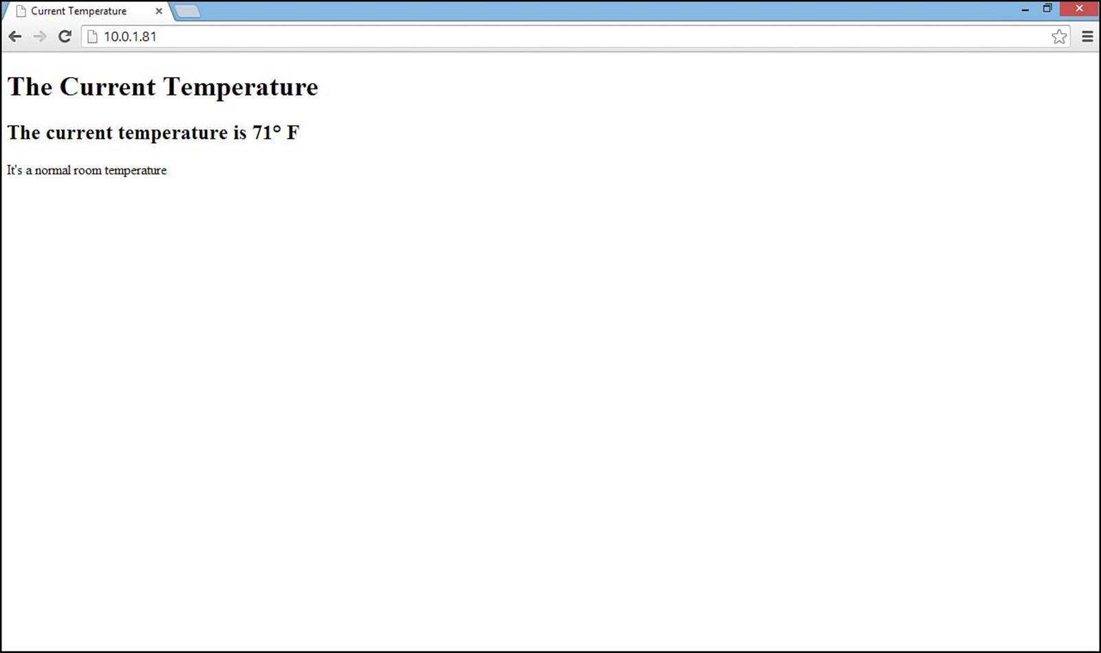
FIGURE 22.2 The web page generated by the sketch.
The simplicity of this example is in the web server code. We don’t care what request the client sends to the web server, so the sketch doesn’t bother trying to read the received data. We just assume that if a remote client is making a request to the web server, it wants to receive the current temperature back!
The first part of the data sent back to the client is the standard HTTP response. After that, the sketch sends an HTML-formatted document that contains the data from the temperature sensor.
Controlling an Arduino from the Web
The next step to using your Arduino on the network is the ability to control the Arduino outputs from a web client. For this exercise, you need to read the actual data sent by the web client, and then use that data to determine which output should be active or inactive.
For this exercise, you control a standard three-light traffic signal from a remote web client. When the web client connects to the Arduino, it will return a web page with three links: one for each light. The client can click a link to turn on the appropriate light.
Building the Circuit
First, you need to build the circuit. This section walks through what you need to set up the traffic signal for the sketch.
For this experiment, you need a few electronic components:
![]() Three LEDs (preferably red, yellow, and green, but they can be the same color if that’s all you have available)
Three LEDs (preferably red, yellow, and green, but they can be the same color if that’s all you have available)
![]() Three 1K-ohm resistors (color code brown, black, red)
Three 1K-ohm resistors (color code brown, black, red)
![]() A breadboard
A breadboard
![]() Four jumper wires
Four jumper wires
Once you gather these components, you can start the experiment.
![]() Try It Yourself: Digital Traffic Signal
Try It Yourself: Digital Traffic Signal
For this experiment, you create a traffic signal that your Arduino will control using three separate digital interfaces. First, follow these steps to build the electronic circuit:
1. Place the three LEDs on the breadboard so that the short leads are all on the same side and so that the two leads straddle the space in the middle of the board so that they’re not connected. Place them so that the red LED is at the top, the yellow LED in the middle, and the green LED is at the bottom of the row.
2. Connect a 1K-ohm resistor between the short lead on each LED to a common rail area on the breadboard.
3. Connect a jumper wire from the common rail area on the breadboard to the GND interface on the Arduino.
4. Connect a jumper wire from the green LED long lead to digital interface 5 on the Arduino.
5. Connect a jumper wire from the yellow LED long lead to digital interface 6 on the Arduino.
6. Connect a jumper wire from the red LED long lead to digital interface 7 on the Arduino.
That completes the hardware circuit. The circuit diagram for what you just created is shown in Figure 22.3.
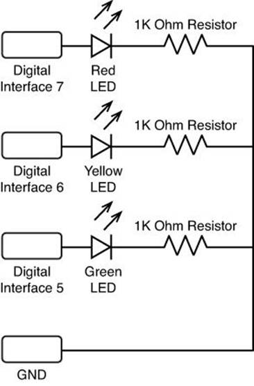
FIGURE 22.3 The circuit diagram for the traffic signal experiment.
Now you’re ready to start coding the sketch that controls the traffic signal circuit from the Web.
Writing the Sketch
For the sketch, you need to create a web server that can read the request sent from a web client, parse the data sent, and activate or deactivate the appropriate LED.
![]() Try It Yourself: Creating the Web Server
Try It Yourself: Creating the Web Server
For the web server sketch, you use the Ethernet library to listen for client connections and then read the data sent by the client. Unfortunately, you can only read the data 1 byte at a time. Because of that, the sketch will need to look for a specific character sequence to trigger which LED should light. The web server will expect the client to send the URI as follows:
http://<ipaddress>/?x
Where <ipaddress> is the IP address assigned to the Arduino, and x is the number of the LED you want to light:
![]() 1 for the red LED
1 for the red LED
![]() 2 for the yellow LED
2 for the yellow LED
![]() 3 for the green LED
3 for the green LED
The question mark before the number gives us a way to parse through the client data and know when to expect the control number to appear.
Here are the steps to create the sketch:
1. Open the Arduino IDE, and enter this code into the editor window:
#include <SPI.h>
#include <Ethernet.h>
byte mac[] = {0x90, 0xa2, 0xda, 0x0e, 0x98, 0x34 };
EthernetServer server(80);
int redLED = 7;
int yellowLED = 6;
int greenLED = 5;
char c;
void setup() {
Serial.begin(9600);
pinMode(redLED, OUTPUT);
pinMode(yellowLED, OUTPUT);
pinMode(greenLED, OUTPUT);
digitalWrite(redLED, LOW);
digitalWrite(yellowLED, LOW);
digitalWrite(greenLED, LOW);
Ethernet.begin(mac);
delay(1000);
Serial.print("The server is on IP address: ");
Serial.println(Ethernet.localIP());
}
void loop() {
EthernetClient client = server.available();
if (client.connected()) {
while (client.available()) {
c = client.read();
if (c == '?') {
c = client.read();
switch(c) {
case '1':
Serial.println("Activate Red LED");
digitalWrite(redLED, HIGH);
digitalWrite(yellowLED, LOW);
digitalWrite(greenLED, LOW);
break;
case '2':
Serial.println("Activate Yellow LED");
digitalWrite(redLED, LOW);
digitalWrite(yellowLED, HIGH);
digitalWrite(greenLED, LOW);
break;
case '3':
Serial.println("Activate Green LED");
digitalWrite(redLED, LOW);
digitalWrite(yellowLED, LOW);
digitalWrite(greenLED, HIGH);
break;
}
client.println("HTTP/1.1 200 OK");
client.println("Content-Type: text/html");
client.println("Connection: close");
client.println();
client.println("<!DOCTYPE html>");
client.println("<html>");
client.println("<head>");
client.println("<title>Arduino Controller</title>");
client.println("</head>");
client.println("<body>");
client.println("<h2>Arduino Controller</h2>");
client.print("<a href=\"");
client.println("/?1\">Activate Red LED</a><br />");
client.print("<a href=\"");
client.println("/?2\">Activate Yellow LED</a><br />");
client.print("<a href=\"");
client.println("/?3\">Activate Green LED</a><br />");
client.println("</body>");
client.println("</html>");
delay(10);
client.stop();
}
}
}
}
2. Save the sketch as sketch2202.
3. Click the Upload icon to verify, compile, and upload the sketch to your Arduino.
4. Make sure that the Arduino is plugged into the network, and then open the serial monitor tool in the Arduino IDE.
5. Press the Reset button on the Ethernet Shield to reset the server.
6. Look at the serial monitor output to see the IP address assigned to the Arduino.
7. Open a browser in a workstation on the network and connect to the URL:
http://<ipaddress>/?0
where <ipaddress> is the numeric IP address shown in the serial monitor output. The 0 will not activate any of the LEDs, but will return the web page that the sketch generates. This should display the web page shown in Figure 22.4.
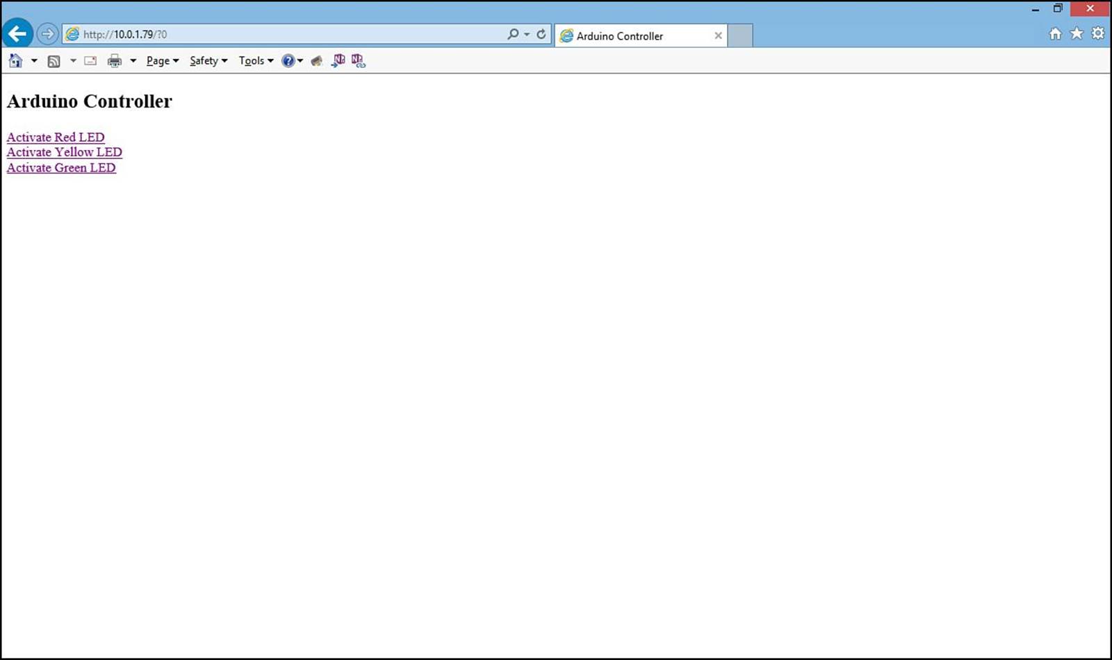
FIGURE 22.4 The main Arduino Controller web page.
8. Click one of the links to activate an LED.
When you click a link on the web page, the associated LED should light up on the Arduino. Clicking each link in the web page sends a new request to the web server. For example, clicking the Activate Red LED link sends the following request:
http://10.0.1.79/?1
The sketch reads the 1 value, which triggers the switch statement to run the digitalWrite functions to activate the red LED and deactivate the yellow and green LEDs.
Instead of using LEDs, you can connect anything to the digital interface pins, such as motors and relays. That enables you to control just about anything from a web client!
Summary
The Ethernet Shield for the Arduino allows you to use your Arduino as a web server on the network. HTTP provides a simple protocol that you can easily work with in your sketches to both send sensor data to remote clients, as well as read requests from remote clients to change the state of interfaces on your Arduino. Remote web clients send HTTP request messages to the Arduino, and the Arduino sends HTTP response messages. To retrieve sensor data, just embed the sensor data in the HTTP response, using the HTML language to format the web page output. To control Arduino interfaces, the client must embed a command inside the HTTP request, and the Arduino sketch much be able to decode the command in the request.
The next hour covers another important feature in Arduino sketches: storing data. The EEPROM included in the Arduino makes for a handy way to store data, but it’s limited in size. To store larger amounts of data, you can use a shield that incorporates an SD card interface. The next hour walks through just how to read and write data using the SD card interface.
Workshop
Quiz
1. What HTTP response code indicates that the request was successfully processed?
A. 300
B. 200
C. 500
2. You must send an HTTP header before you can send HTML data. True or false?
3. Which EthernetClient method should you use to check whether the remote client has connected to the server?
Answers
1. B. The HTTP server must return a 200 response code to indicate the HTTP request was received and processed correctly.
2. True. The HTTP response requires that you send an HTTP response header before you can send the HTML data to create the web page for the client.
3. After assigning the server.available method output to an EthernetClient object, you can use the connected method to determine whether the client is connected to the server, and the available method to determine whether there is data sent by the client.
Q&A
Q. How many digital inputs can you control on the Arduino Uno from a web server sketch?
A. Because the Ethernet Shield requires digital interface pins 10, 11, 12, and 13 to communicate to the Arduino, you can only use pins 0 through 9 for your sketches.
Q. Can multiple remote clients connect to the Arduino web server at the same time?
A. Yes. The server.available method will continue to listen for incoming connections and will accept connections from multiple remote clients at the same time. This requires you to be careful when controlling the Arduino from a remote client. Remember that more than one client can connect and send commands at the same time.
All materials on the site are licensed Creative Commons Attribution-Sharealike 3.0 Unported CC BY-SA 3.0 & GNU Free Documentation License (GFDL)
If you are the copyright holder of any material contained on our site and intend to remove it, please contact our site administrator for approval.
© 2016-2026 All site design rights belong to S.Y.A.