Sams Teach Yourself Arduino Programming in 24 Hours (2015)
Part I: The Arduino Programming Environment
Hour 2. Creating an Arduino Programming Environment
What You’ll Learn in This Hour:
![]() How microcontrollers work
How microcontrollers work
![]() How microcontroller programs work
How microcontroller programs work
![]() What the Arduino Programming Language is
What the Arduino Programming Language is
![]() How to download and install the Arduino IDE
How to download and install the Arduino IDE
Just having an Arduino hardware platform isn’t enough to get your projects working. Besides the hardware, you’ll also need to write a program to tell the Arduino hardware what to do. This hour walks through the basics of how microcontrollers work, how they read and run programs, and how to set up an environment to create programs for your Arduino.
Exploring Microcontroller Internals
Before you can start programming the Arduino, it helps to know a little bit about what’s going on inside of it. At the core of all Arduino units is an ATmega AVR series microcontroller. The programs that you write to control the Arduino must run on the ATmega microcontroller. This section examines the layout of the ATmega microcontroller, showing you the different components and how they interact to run your programs.
Peeking Inside the ATmega Microcontroller
To refresh your memory from the first hour, three basic components reside inside of a microcontroller:
![]() The CPU
The CPU
![]() Memory
Memory
![]() The input/output (I/O) interface
The input/output (I/O) interface
Each of these components plays a different role in how the microcontroller interfaces with your project and in how you program the microcontroller. Figure 2.1 shows the layout of these components in a microcontroller.
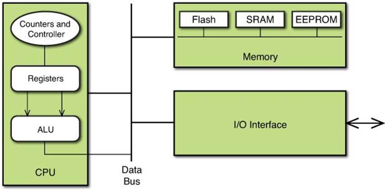
FIGURE 2.1 The ATmega microcontroller block layout.
Now let’s take some time to look inside each of these individual components and see how they work together to run your programs.
The CPU
The CPU inside the microcontroller isn’t all that different from the CPU you would find in your workstation computer, just a little smaller. It consists of several common parts found in most computer systems:
![]() An Arithmetic Logic Unit (ALU), which performs the mathematical and logical operations
An Arithmetic Logic Unit (ALU), which performs the mathematical and logical operations
![]() Data registers, which store data for processing in the ALU
Data registers, which store data for processing in the ALU
![]() A status register, which contains the status information of the most recently executed arithmetic instruction
A status register, which contains the status information of the most recently executed arithmetic instruction
![]() A program counter, which keeps track of the memory location of the next instruction to run
A program counter, which keeps track of the memory location of the next instruction to run
![]() A stack pointer, which keeps track of the location of temporary data stored in memory
A stack pointer, which keeps track of the location of temporary data stored in memory
![]() A controller, which handles loading program code and memory data into the registers, ALU, and pointers
A controller, which handles loading program code and memory data into the registers, ALU, and pointers
All the CPU components interact within the CPU based on a clocking signal provided to the microcontroller. At each clock pulse, the CPU performs one operation. The speed of the clock pulse determines how fast the CPU processes instructions.
For example, the Arduino Uno utilizes a 16MHz clock, which provides 16 million clock pulses per second. Most of the ATmega microcontroller CPU instructions require only one or two clock pulses to complete, making the Arduino capable of sampling inputs at a very high rate.
Memory
The Atmel ATmega microcontroller family uses what’s called the Harvard architecture for computers. This model separates the computer memory into two components: one memory section to store the program code, and another memory section to store the program data.
The ATmega microcontroller family uses a separate form of memory for each type:
![]() Flash memory to store program code
Flash memory to store program code
![]() Static random-access memory (SRAM) to store program data
Static random-access memory (SRAM) to store program data
The flash memory retains data after you remove power from the microcontroller. That way your program code stays in memory when you power off the Arduino. When you turn the Arduino back on, it starts running your program immediately without you having to reload it each time.
SRAM memory does not retain data when the power is off, so any data your program stores in SRAM will be lost at power down. To compensate for that, the ATmega microcontroller also incorporates a separate electronically erasable programmable read-only memory (EEPROM) memory section besides the SRAM for storing data.
The EEPROM memory can retain data after loss of power, until you manually clear it out. It’s not as fast as the SRAM memory, so you should use it only when you need to save data for later use.
Input/Output interface
The I/O interface allows the microcontroller to interact with the outside world. This is what allows the ATmega controller to read analog and digital input signals and send digital output signals back to external devices.
The ATmega controller contains a built-in analog-to-digital converter (ADC), which converts analog input signals into a digital value that you can read from your programs. It also contains circuitry to control the digital interface pins so that you can use the same pins for either digital input or digital output.
Tip: Analog Output
You might have noticed that the ATmega microcontroller doesn’t have any analog output interfaces. The reason for that is you can simulate an analog output by using digital outputs and a technique called pulse-width modulation (PWM). PWM sends a digital signal of a varying duration and frequency, thus emulating an analog output signal. The ATmega328 microcontroller used in the Arduino Uno supports six PWM outputs.
All the microcontroller components work together to process input signals and generate output signals. The CPU is what controls all the action. The next section takes a closer look at just how the CPU functions in the microcontroller.
Programming the Microcontroller
You control what happens in the CPU using software program code. The CPU reads the program code instructions, and then performs the specified actions one step at a time. Each type of CPU has its own specific instructions that it understands, called its instruction set.
The instruction set is what tells the CPU what data to retrieve and how to process that data. This is where your programming comes in. Operations such as reading data, performing a mathematical operation, or outputting data are defined in the instruction set.
Because the CPU can only read and write binary data, the instruction set consists of groups of binary data, usually consisting of 1- or 2-byte commands. These commands are called machine code (also commonly called operation codes, or opcodes for short). Each instruction has a specific binary code to indicate the instruction, along with what data the instruction requires.
The ATmega AVR instruction set uses 16-bit (2-byte) instructions to control the CPU actions. For example, the instruction to add the data values stored in registers R1 and R2, and then place the result in register R1, looks like this:
0000 1100 0001 0010
When the CPU processes this instruction, it knows to fetch the data values from the registers, use the ALU to add them, and then place the result back in register R1.
Knowing just what machine codes do what functions, and require what data, can be an almost impossible task for programmers. Fortunately, there’s some help with that, as discussed in the next section.
Moving Beyond Machine Code
Machine code is used directly by the microcontroller to process data, but it’s not the easiest programming language for humans to read and understand. To solve that problem, developers have created some other ways to create program code. This section looks at those methods and explains how they can help with your Arduino programming.
Coding with Assembly Language
Assembly language is closely related to machine code; it assigns a text mnemonic code to represent each individual machine code instruction. The text mnemonic is usually a short string that symbolizes the function performed (such as ADD to add two values). That makes writing basic microcontroller programs a lot easier.
For example, if you remember from the preceding section, the machine code to add the values stored in register R1 to the value stored in register R2 and place the result in register R1 looks like this:
0000 1100 0001 0010
However, the assembly language code for that function looks like this:
add r1, r2
Now that makes a lot more sense for humans, and is a lot easier to remember for coding. Each of the machine code instructions for the ATmega AVR family of microcontrollers has an associated assembly language mnemonic. These are listed in the AVR Instruction Set Manual, available for download from the Atmel website.
Tip: The AVR Instruction Set
If you’re curious, you can download the complete AVR instruction set from the Atmel website at http://www.atmel.com/images/doc0856.pdf.
The ATmega AVR series of microcontrollers (which is what the Arduino uses) has 282 separate instructions that they recognize, so there are 282 separate assembly language mnemonics. The instructions can be broken down into six categories:
![]() Load data from a memory location into a register.
Load data from a memory location into a register.
![]() Perform mathematical operations on register values.
Perform mathematical operations on register values.
![]() Compare two register values.
Compare two register values.
![]() Copy a register value to memory.
Copy a register value to memory.
![]() Branch to another program code location.
Branch to another program code location.
![]() Interact with a digital I/O interface.
Interact with a digital I/O interface.
There are separate instructions for each register, each mathematical operation, and each method for copying data to and from memory. It’s not hard to see why there are 282 separate instructions.
While the Atmel AVR assembly language is an improvement over coding machine language, creating fancy programs for the Arduino using assembly language is still somewhat difficult and usually left to the more advanced programmers. Fortunately for us, there’s an even easier way to program the Arduino unit, as covered in the next section.
Making Life Easier with C
Even when using the Atmel AVR assembly language, it can still be quite the challenge trying to remember just which of the 282 separate instructions you need to use for any given operation. Fortunately for us, yet another level of programming makes life much easier for programmers.
Higher-level programming languages help separate out having to know the inner workings of the microcontroller from the programming code. Higher-level programming languages hide most of the internal parts of the CPU operation from the programmer, so that the programmer can concentrate on just coding.
For example, with higher-level programming languages, you can just assign variable names for data, and the compiler converts those variable names into the proper memory locations or registers for use with the CPU. With a higher-level programming language, to add two numbers and place the result back into the same location, you just write something like this:
value1 = value1 + value2;
Now that’s even better than the machine code version.
The key to using higher-level programming languages is that there must be a compiler that can convert the user-friendly program code into the machine language code that runs in the microcontroller. That’s done with a combination of a compiler and a code library.
The compiler reads the higher-level programming language code and converts it into the machine language code. Because it must generate machine language code, the compile is specific to the underlying CPU that the program will run. Different CPUs require different compilers.
Besides being able to convert the higher-level programming language code into machine code, most compilers also have a set of common functions that make it easier for the programmer to write code specific for the CPU. This is called a code library. Again, different CPUs have different libraries to access their features.
Many different higher-level programming languages are available these days, but the Atmel developers chose the popular C programming language as the language to use for creating code for the AVR microcontroller family. They released a compiler for converting C code into the AVR microcontroller machine language code, in addition to a library of functions for interacting with the specific digital and analog ports on the microcontroller.
When the Arduino project developers chose the ATmega microcontroller for the project, they also wanted to make coding projects easy for nonprogrammers. To do that, they built on to the existing Atmel C language compiler and library and created yet another library of code specific to using the AVR microcontroller in the Arduino environment. The next section explores both the Atmel and Arduino C language libraries.
Creating Arduino Programs
Currently, two main C language libraries are available for the Arduino environment:
![]() The Atmel C library
The Atmel C library
![]() The Arduino project library
The Arduino project library
The Atmel C library is created for using ATmega microcontrollers in general, and the Arduino project library is created specifically for nonprogrammers to use for the Arduino unit. This section takes a brief look at the two separate Arduino programming environments to familiarize you with features each provides for the Arduino programmer.
Exploring the Atmel C Library
The Atmel C environment consists of two basic packages:
![]() A command-line compiler environment
A command-line compiler environment
![]() A graphical front end to the compiler environment
A graphical front end to the compiler environment
The AVR Libc project (http://www.nongnu.org/avr-libc/) has worked on creating a complete C language command-line compiler and library for the ATmega AVR family of microcontrollers. It consists of three core packages:
![]() The avr-gcc compiler for creating the microcontroller machine code from C language code
The avr-gcc compiler for creating the microcontroller machine code from C language code
![]() The avr-libc package for providing C language libraries for the AVR microcontroller
The avr-libc package for providing C language libraries for the AVR microcontroller
![]() The avr-binutils package for providing extra utilities for working with the C language programs
The avr-binutils package for providing extra utilities for working with the C language programs
The avr-gcc package uses the open source GNU C compiler (called gcc), and customizes it to output the AVR machine code instruction set code used in the ATmega microcontrollers. This is what allows you to write C programs that are converted into the machine code that runs on the microcontroller.
Tip: The avr-gcc Package
If you’re curious, you can find a Windows version of the avr-gcc command-line compiler in the WinAVR package at http://winavr.sourceforge.net/.
However, these days just about every application uses a graphical interface, including compilers. The Atmel developers have released a full integrated development environment (IDE) package that provides a graphical windows environment for editing and compiling C programs for the AVR microcontroller.
The Atmel Studio package combines a graphical text editor for entering code with all the word processing features you’re familiar with (such as cutting and pasting text) with the avr-gcc compiler. It also incorporates a full C language debugger, making it easier to debug your program code. In addition, it outputs all the error messages generated by the microcontroller into the graphical window.
Although the Atmel C library makes programming the ATmega series of microcontrollers easier, it’s still considered to be a tool for advanced programmers. Instead, most Arduino beginners (and even many advanced users) use the Arduino programming tools created by the Arduino project. The next section walks through these.
Tip: Exploring the Atmel Studio Package
If you’re interested in exploring the Atmel Studio software, you can find more information, including a link to download the Atmel Studio software, at http://www.atmel.com/tools/ATMELSTUDIO.aspx.
Using the Arduino Programming Tools
One downside to the Atmel C library is that it uses generic code for interfacing with the ATmega microcontroller. The benefit of the Arduino hardware is that it makes accessing the specific features of the ATmega microcontroller easier, but that’s lost if you just use the Atmel C library code.
Fortunately, the Arduino development team has helped solve that problem for us by creating the Arduino Programming Language.
Examining the Arduino Programming Language
The Arduino developers have created a C library that contains additional functions to help make interacting with the Arduino features much easier than coding with the Atmel C library.
For example, to send a signal to a digital output line, you simply use the function digitalWrite(). To read a signal from an analog input line, you use the function analogRead(). That makes writing code for the Arduino much easier.
The Arduino developers released this customized C library along with the Atmel avr-gcc C language compiler in a single package, called the Arduino IDE. The Arduino IDE is a graphical interface, similar to the Atmel Studio package but not quite as complex. Figure 2.2 shows the basic Arduino IDE window.
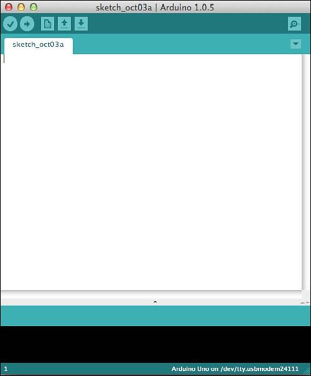
FIGURE 2.2 The Arduino IDE software package.
The IDE includes a full editor for creating your Arduino programs, a compiler to build the finished program, and a method to upload your completed program into the Arduino unit. Creating programs to run on the Arduino is a breeze with the Arduino IDE.
The Arduino Shield Libraries
Besides the core Arduino C libraries, the Arduino developers have created libraries for all the common Arduino shield devices. This allows you to easily incorporate the features of a shield into your programs without having to write complicated code.
Specialty libraries are available for all the popular Arduino shields, such as the following:
![]() Ethernet
Ethernet
![]() LCD display
LCD display
![]() Motor controller
Motor controller
![]() SD card
SD card
The Arduino IDE contains all the popular shield libraries by default, so you don’t have to go hunting on the Internet looking for files to download. With the Arduino IDE and the shield libraries, you can create programs for just about any Arduino project that you’ll work on.
Installing the Arduino IDE
Unfortunately, the Arduino units don’t come with the Arduino IDE software. Before you can get started with the Arduino IDE, you have to download it from the Arduino website and install it on to your workstation. This section walks through that process for each of the platforms supported by the Arduino IDE.
Downloading the Arduino IDE
The Arduino project maintains a web page specifically to support the Arduino IDE package (http://arduino.cc/en/main/software). When you go to that site, you’ll find links to the latest version of the Arduino IDE for three platforms:
![]() Windows
Windows
![]() OS X
OS X
![]() Linux
Linux
Besides packages built for these three platforms, the Arduino project also provides the source code for the complete Arduino IDE package. So, if you’re adventurous (and experienced in compiling programs), you can download the source code and compile it on whatever platform you need.
Caution: Beta Software
The Arduino download web page often contains a link to a development version of the Arduino IDE software. This is considered beta software and therefore may contain bugs and features that don’t work yet. For beginners, it’s usually a good idea to avoid testing beta software until you’ve become more familiar with how the Arduino and the Arduino IDE work.
Just click the Download link for the package you need for your development platform. After you download the Arduino IDE package, you’re ready to install it, as covered in the following sections for the three different environments.
Installing for Windows
You might have noticed that there are two download versions for the Windows platform:
![]() A standard Windows install file
A standard Windows install file
![]() A zip file
A zip file
The install file version contains both the Arduino IDE software and the driver files necessary for Windows to recognize the Arduino when you connect it via a USB cable. The installer runs a wizard, which automatically installs the software and drivers. It is the easiest way to install the Arduino IDE environment, and is recommended.
The zip file just contains the Arduino IDE files along with the Windows driver files. You’ll need to install the driver files manually using the Windows Device Manager tool.
This section walks through the installation process for both methods.
Using the Windows Installer File
When you run the Windows installer file, a wizard utility starts up, guiding you through the software installation, as shown in Figure 2.3.
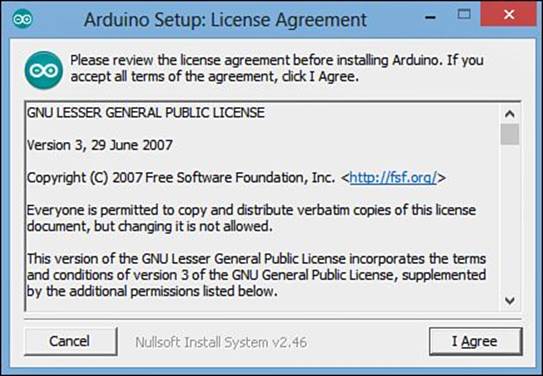
FIGURE 2.3 The Windows Arduino IDE installation wizard.
The wizard guides you through the steps for installing the Arduino IDE software. You can accept the default folder location to install the Arduino software or change it if you prefer to store the program files in another location.
After the software installs, the wizard installs the Arduino software drivers necessary for Windows to interface with your Arduino.
Just follow the prompts in the wizard to complete the software and driver installation.
Using the Windows Zip File
If you choose to download the Windows zip file version of the software, you’ll find the installation a bit more complicated. The zip file contains all the same files as the Windows installer version, but it doesn’t automatically install them.
To run the Arduino IDE, just extract the zip file contents into a folder and look for the arduino.exe program file. You can create a shortcut to this file on your desktop for easy access.
However, before you can use the Arduino IDE, you must manually install the Windows drivers for the Arduino unit. The following steps walk through how to do that.
![]() Try It Yourself: Installing the Arduino Drivers Manually
Try It Yourself: Installing the Arduino Drivers Manually
1. After unzipping the Windows zip file to a folder, plug your Arduino unit into the USB port on your workstation.
2. The Windows USB utility will appear, but will complain that it is unable to find the driver for the Arduino unit.
3. Open the Device Manager interface in your Windows workstation, as shown in Figure 2.4.
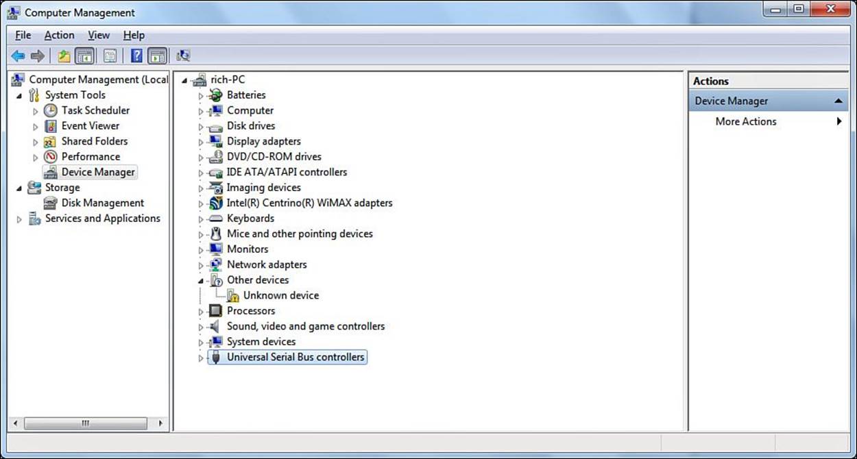
FIGURE 2.4 The Windows Device Manager showing an unknown device.
4. Double-click the Unknown device entry.
5. Click the Update Driver button in the Unknown Device Properties dialog box.
6. Select the Browse My Computer for Driver Software option.
7. Navigate to the folder where you unzipped the Arduino Windows zip file in the \drivers folder.
8. Click the Install button for the Arduino USB driver dialog box.
9. The Device Manager should now show the Arduino unit listed as a COM port on your workstation, as shown in Figure 2.5.
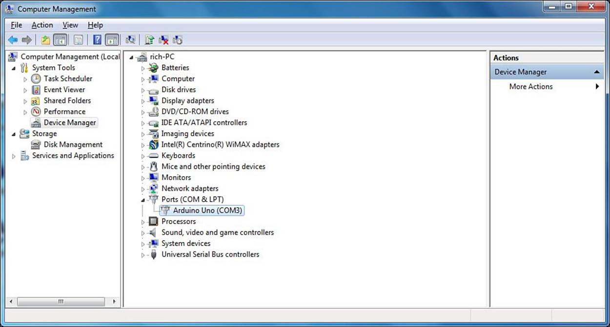
FIGURE 2.5 The installed Arduino USB driver COM port.
It’s a good idea to note the COM port assigned to the Arduino unit (shown as COM3 in the Figure 2.5 example). You’ll need that information later on when you configure the Arduino IDE software.
Installing for OS X
The OS X installation software provides only a zip file to download. Follow these steps to get the Arduino IDE package installed in your OS X environment.
![]() Try It Yourself: Installing the Arduino IDE for OS X
Try It Yourself: Installing the Arduino IDE for OS X
1. Download the most recent release of the OS X package for the Arduino IDE (currently the file arduino-1.0.5-macosx.zip).
2. Double-click the installation file to extract the Arduino IDE application file.
3. Move the Arduino application file to the Applications folder on your Mac.
After you install the Arduino IDE software, you can connect your Arduino using a USB cable. The OS X system will automatically recognize the Arduino as a new network interface, as shown in Figure 2.6.
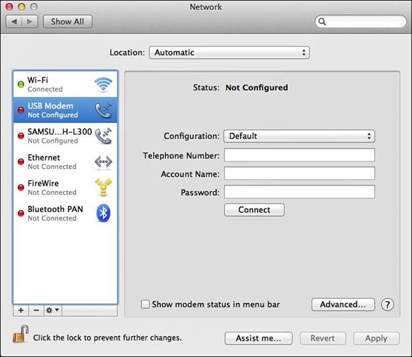
FIGURE 2.6 An OS X system detecting an Arduino device.
Caution: Arduino Status
After you install the Arduino device in OS X, the device will appear in a Not Configured status. Don’t worry, the Arduino will work just fine.
Installing for Linux
The Linux installation provides for two separate zip files:
![]() A 32-bit version
A 32-bit version
![]() A 64-bit version
A 64-bit version
You’ll need to select the version appropriate for your specific Linux distribution. Both versions are distributed as a .tar.gz file format, commonly called a tarball in Linux circles.
To extract the tarball into a folder, you use the tar command, and add the -z option to uncompress the tarball as it extracts the files:
rich@myhost ~> tar –zxf arduino.tar.gz
The resulting file is the Arduino IDE executable program file. Just create a shortcut on your desktop to the file.
Tip: Arduino and Ubuntu
The Ubuntu Linux distribution includes the Arduino IDE software in the standard software repository. You can install the Arduino IDE software using the standard Ubuntu Package Manager program. There are two packages to install: arduino and arduino-core. When you install these packages, Ubuntu automatically places a link to the Arduino IDE software in the Unity desktop menu.
Summary
In this hour, you learned how you can write code to program the Arduino. The core of the Arduino is the ATmega microcontroller, so the code you write must be able to run on that system. The ATmega microcontroller uses machine language code to handle data and interface with the input and output ports. However, you can use the Atmel C programming language library to make coding easier. Also, the Arduino development team has expanded on the Atmel C language and provided their own programming environment and libraries. This makes creating code for the Arduino much easier. You can download the Arduino IDE package from the Arduino website for the Windows, OS X, and Linux platforms.
In the next hour, we take a closer look at the Arduino IDE window. You’ll learn how to create, edit, compile, debug, and upload your Arduino programs, all from one place!
Workshop
Quiz
1. Which part of the microcontroller performs the addition of two numbers?
A. The ALU
B. The registers
C. The memory
D. The I/O interface
2. SRAM memory stores your program data, even after you turn off the Arduino unit. True or false?
3. Why doesn’t the Arduino have any analog output ports?
Answers
1. A. The Arithmetic Logic Unit (ALU) performs all mathematical operations on data in the microcontroller.
2. False. The SRAM memory loses its contents when the Arduino power is off. You must store any data you want to keep either in the EEPROM memory or in a removable storage device, such as an SD card.
3. The Arduino uses pulse-width modulation (PWM) to simulate an analog output signal using a digital output port. That allows you to use the digital output ports to generate either a digital or analog output.
Q&A
Q. Can I write assembly language programs and upload them to the Arduino?
A. Yes, you can write assembly language programs using the Arduino IDE and compile them using the avr-gcc compiler. However, you must be careful when doing that, because you have to keep track of the registers and memory locations in your program!
Q. Is the Atmel Studio IDE free?
A. Yes, the Atmel Studio IDE is free software, but it’s not open source software.
All materials on the site are licensed Creative Commons Attribution-Sharealike 3.0 Unported CC BY-SA 3.0 & GNU Free Documentation License (GFDL)
If you are the copyright holder of any material contained on our site and intend to remove it, please contact our site administrator for approval.
© 2016-2026 All site design rights belong to S.Y.A.