Sams Teach Yourself Arduino Programming in 24 Hours (2015)
Part I: The Arduino Programming Environment
Hour 4. Creating an Arduino Program
What You’ll Learn in This Hour:
![]() Building an Arduino sketch
Building an Arduino sketch
![]() Compiling and running a sketch
Compiling and running a sketch
![]() Interfacing your Arduino to electronic circuits
Interfacing your Arduino to electronic circuits
Now that you’ve seen what the Arduino is and how to program it using the Arduino IDE, it’s time to write your first program and watch it work. In this hour, you learn how to use the Arduino IDE software package to create, compile, and upload an Arduino program. You then learn how to interface your Arduino with external electronic circuits to complete your Arduino projects.
Building an Arduino Sketch
Once you have your Arduino development environment set up, you’re ready to start working on projects. This section covers the basics that you need to know to start writing your sketches and getting them to run on your Arduino.
Examining the Arduino Program Components
When you use the Arduino IDE package, your sketches must follow a specific coding format. This coding format differs a bit from what you see in a standard C language program.
In a standard C language program, there’s always a function named main that defines the code that starts the program. When the CPU starts to run the program, it begins with the code in the main function.
In contrast, Arduino sketches don’t have a main function in the code. The Arduino bootloader program that’s preloaded onto the Arduino functions as the sketch’s main function. The Arduino starts the bootloader, and the bootloader program starts to run the code in your sketch.
The bootloader program specifically looks for two separate functions in the sketch:
![]() setup
setup
![]() loop
loop
The Arduino bootloader calls the setup function as the first thing when the Arduino unit powers up. The code you place in the setup function in your sketch only runs one time; then the bootloader moves on to the loop function code.
The setup function definition uses the standard C language format for defining functions:
void setup() {
code lines
}
Just place the code you need to run at startup time inside the setup function code block.
After the bootloader calls the setup function, it calls the loop function repeatedly, until you power down the Arduino unit. The loop function uses the same format as the setup function:
void loop() {
code lines
}
The meat of your application code will be in the loop function section. This is where you place code to read sensors and send output signals to the outputs based on events detected by the sensors. The setup function is a great place to initialize input and output pins so that they’re ready when the loop runs, then the loop function is where you use them.
Including Libraries
Depending on how advanced your Arduino program is, you may or may not need to use other functions found in external library files. If you do need to use external libraries, you first need to define them at the start of your Arduino program, using the #include directive:
#include <library>
The #include directives will be the first lines in your sketch, before any other code.
If you’re using a standard Arduino shield, most likely the shield library code is already included in the Arduino IDE package. Just choose Sketch > Import Library from the menu bar, and then select the shield that you’re using. The Arduino IDE automatically adds the #include directives required to write code for the requested shield. For example, if you select the Ethernet shield, the following lines are imported into the sketch:
#include <Dhcp.h>
#include <Dns.h>
#include <Ethernet.h>
#include <EthernetClient.h>
#include <EthernetServer.h>
#include <EthernetUdp.h>
#include <util.h>
That saves a lot of time from having to go hunting around to find the libraries required for a specific shield.
Creating Your First Sketch
Now that you’ve seen the basics for creating an Arduino program, let’s dive in and create a simple sketch to get a feel for how things work.
Working with the Editor
When you open the Arduino IDE, the editor window starts a new sketch. The name of the new sketch appears in the tab at the top of the editor window area, in the following format:
sketch_mmmddx
where mmm is a three-letter abbreviation of the month, dd is the two-digit numerical date, and x is a letter to make the sketch name unique for the day (for example, sketch_jan01a).
As you type your sketch code into the editor window, the editor will color-code different parts of the sketch code, such as making function names brown and text strings blue. This makes it easier to pick out syntax errors, and comes in handy when you’re trying to debug your sketch.
Now you’re ready to start coding. Listing 4.1 shows the code for the sketch0401 file that we’ll use to test things out. Enter this code into the Arduino IDE editor window.
LISTING 4.1 The sketch0401 Code
int counter = 0;
int pin = 13;
void setup() {
Serial.begin(9600);
pinMode(pin, OUTPUT);
digitalWrite(pin, LOW);
}
void loop() {
counter = counter + 1;
digitalWrite(pin, HIGH);
Serial.print("Blink #"); Serial.println(counter);
delay(1000);
digitalWrite(pin, LOW);
delay(1000);
}
You’ll learn what all these different lines of code mean as you go through the rest of the hours, so don’t worry too much about the code for now. The main point now is to have a sketch to practice compiling and running.
The basic idea for this code is to make the Arduino blink the L LED connected to digital port 13 on the Arduino once per second, and also output a message to the Arduino serial port, counting each blink.
After you enter the code into the editor window, choose File > Save As from the menu bar to save the sketch as sketch0401. Now you’re ready to verify and compile the sketch.
Compiling the Sketch
The next step in the process is to compile the sketch code into the machine language code that the Arduino runs.
Click the verify icon on the toolbar (the checkmark icon), or choose Sketch > Verify/Compile from the menu bar. Figure 4.1 shows the results that you should get if things worked correctly.
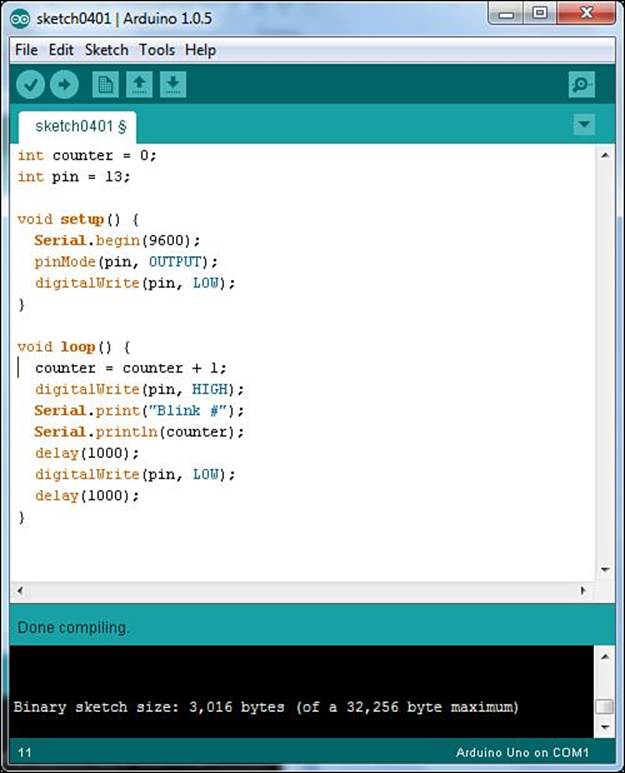
FIGURE 4.1 Compiling the sketch0401 code.
As shown in Figure 4.1, you should see a message in the message area that the compile has completed, and the console window should show the final size of the compiled machine language code that will be uploaded to the Arduino.
If you have any typos in the sketch code that cause the compile process to fail, you’ll see an error message in the message area, as shown in Figure 4.2.
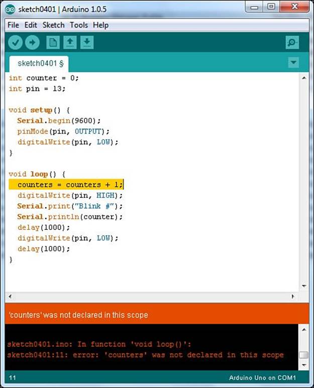
FIGURE 4.2 A compiler error displayed in the Arduino IDE.
The Arduino IDE also highlights the line of code that generated the error, making it easier for you to pick out the problem. Also, a more detailed error message appears in the console window area to help even more.
After you get the sketch to compile without any errors, the next step is to upload it to your Arduino.
Uploading Your Sketch
The key to successfully uploading sketches to your Arduino unit is in defining how the Arduino is connected to your workstation. Hour 3, “Using the Arduino IDE,” walked through how to use the Tools > Serial Port menu bar option to set which serial port your Arduino is connected to. After you set that, you should be able to easily upload your compiled sketches.
Just click either the upload icon on the toolbar (the right arrow icon), or select File > Upload from the menu bar. Before the upload starts, the Arduino IDE recompiles the sketch code. This comes in handy when you’re just making quick changes; you can compile and upload the new code with just one click.
When the upload starts, you should see the TX and RX LEDs on the Arduino blink, indicating that the data transfer is in progress. When the upload completes, you should see a message in both the Arduino IDE message area and console window indicating that the upload was completed. If anything does go wrong, you’ll see an error message appear in both the message area and the console window, as shown in Figure 4.3.
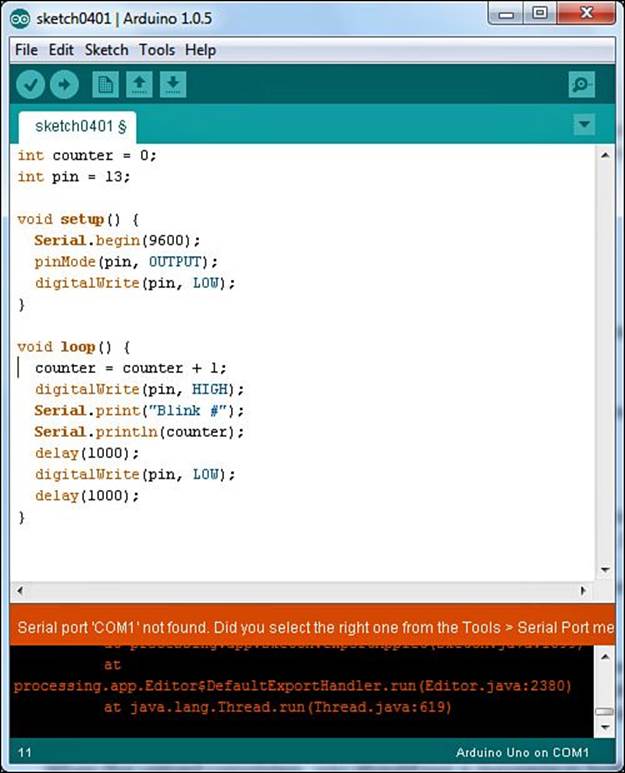
FIGURE 4.3 Upload problem message in the Arduino IDE.
If all goes well, you’re ready to start running your sketch on the Arduino. The next section shows you how.
Running Your Program
Now that the sketch code is uploaded onto your Arduino, you’re ready to start running it. However, you might have noticed that once the upload process finished in the Arduino IDE, the L and the TX LEDs on your Arduino unit already started to blink. That’s your sketch running. When the upload process completes, the bootloader automatically reboots the Arduino and runs your program code.
The L LED is blinking because of the digitalWrite() function setting the digital pin 13 first to 0 (no voltage) and then after a second, setting it to 1 (producing a 5V signal). The TX LED is blinking because the Serial.print() function is sending data out the serial port.
You can view the output from the serial port on your Arduino using the serial monitor built in to the Arduino IDE. Just choose Tools > Serial Monitor from the menu bar, or click the serial monitor icon (the magnifying glass icon) on the toolbar. The serial monitor window appears and displays the output received from the Arduino, as shown in Figure 4.4.
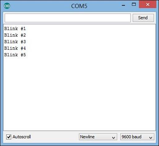
FIGURE 4.4 Viewing the Arduino serial port output from the serial monitor.
You might have noticed that after you started the serial monitor, the blink count output restarted back at 1. When you start serial monitor, it sends a signal to the Arduino to reset it, which in turn runs the bootloader to reload the sketch and start over from the beginning.
You can also manually restart a running sketch using the Reset button on the Arduino. On the Arduino Uno R3, you’ll find the Reset button in the upper-left corner of the circuit board. Just push the button and release it to reset the Arduino.
You don’t have to connect the Arduino to the USB port on your workstation for it to run. You can run the Arduino from an external power source, as well, such as a battery pack or AC/DC converter. Just plug the power source into the power socket on the Arduino unit. The Arduino Uno R3 automatically detects power applied to either the USB port or the power port and starts the bootloader program to start your sketch.
Interfacing with Electronic Circuits
While getting your sketch uploaded to the Arduino and running is a significant accomplishment, most likely you’ll want to do more in your Arduino projects than just watch the L LED blink. That’s where you’ll need to incorporate some type of external electronic circuits into your projects. This section covers the basics of what you need to know to add external electronic circuits to your Arduino sketches.
Using the Header Sockets
The main use of the Arduino is to control external electronic circuits using the input and output signals. To do that, you need to interface your electronic circuits with the Arduino analog and digital signals. This is where the header sockets come into play.
If you remember from Hour 1, “Introduction to the Arduino,” the header sockets are the two rows of sockets at the top and bottom of the Arduino Uno circuit board. (Some more advanced Arduino units, such as the Arduino Mega, also include a third header socket on the right side of the board to support additional ports.) You’ll plug your electronic circuits into the sockets to gain access to the Arduino input and output signals, as well as the power from the Arduino.
The basic Arduino Uno unit that we’re using for our experiments uses the standard Arduino two-row header socket format. Figure 4.5 shows the layout of the upper and lower header sockets.
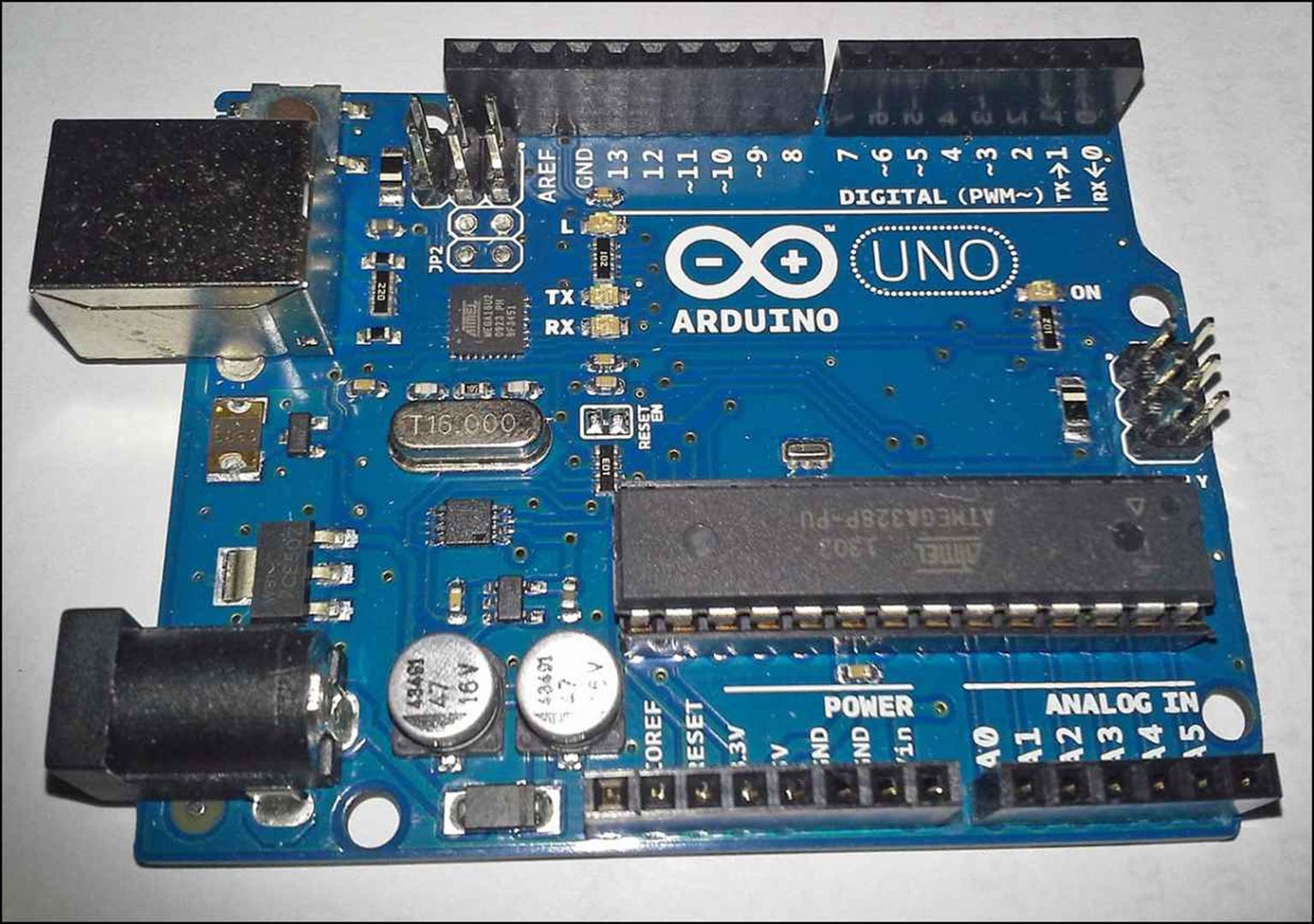
FIGURE 4.5 The Arduino Uno upper and lower header sockets.
The lower header socket has 13 ports on it, as described in Table 4.1.
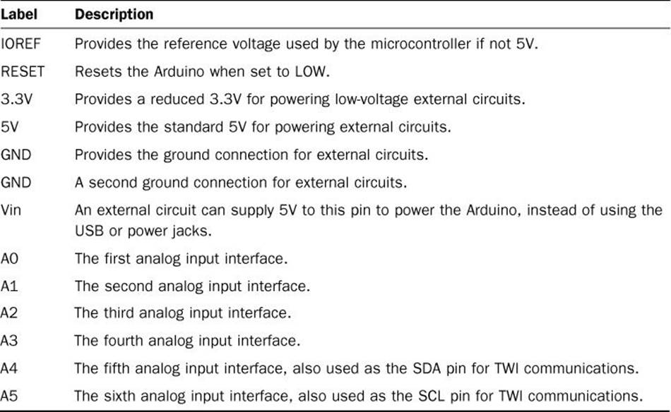
TABLE 4.1 The Arduino Uno Lower Header Socket Ports
The upper header socket has 16 ports on it, as described in Table 4.2
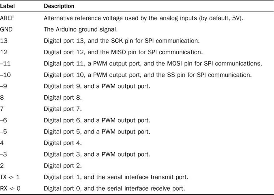
TABLE 4.2 The Arduino Uno Upper Header Socket Ports
For our test sketch, we need to access the digital port 13 socket, in addition to a GND socket, to complete the electrical connection to power our electronic devices.
To access the sockets, you can plug wires directly into the socket ports. To make it easier, you can use jumper wires, which you can easily remove when you finish experimenting.
Building with Breadboards
When you build an electronic circuit, the layout is usually based on a schematic diagram that shows how the components should be connected. The schematic shows a visual representation of which components are connected to which, using standard symbols to represent the different components, such as resistors, capacitors, transistors, switches, relays, sensors, and motors.
Your job is to build the electronic circuit to mimic the layout and connections shown in the schematic diagram. In a permanent electronic circuit, you use a printed circuit board (called PCB) to connect the components according to the schematic.
In a PCB, connections between the electronic components are etched into the PCB using a metallic conductor. To place the electronic components onto the PCB, you must solder the leads of the components onto the PCB.
The downside to using a PCB for your electronic project is that because it’s intended to be permanent, you can’t easily make changes. Although that’s fine for final circuits, when you’re developing a new system and experimenting with different circuit layouts, it’s somewhat impractical to build a new PCB layout for each test.
This is where breadboards come in handy. A breadboard provides an electronic playground for you to connect and reconnect electronic components as you need. Figure 4.6 shows a basic breadboard layout.
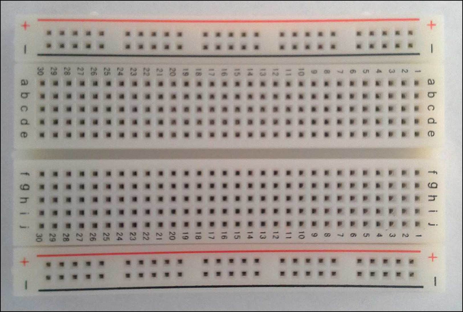
FIGURE 4.6 A basic breadboard.
Breadboards come in many different sizes and layouts, but most breadboards have these features:
![]() A long series of sockets interconnected along the ends of the breadboard. These are called buses (or sometimes rails), and are often used for the power and ground voltages. The sockets in the bus are all interconnected to provide easy access to power in the circuit.
A long series of sockets interconnected along the ends of the breadboard. These are called buses (or sometimes rails), and are often used for the power and ground voltages. The sockets in the bus are all interconnected to provide easy access to power in the circuit.
![]() A short series of sockets (often around five) interconnected, and positioned across a gap in the center of the breadboard. Each group of sockets is interconnected to provide an electrical connection to the components plugged into the same socket group. The gap allows you to plug integrated circuit chips into the breadboard and have access to the chip leads.
A short series of sockets (often around five) interconnected, and positioned across a gap in the center of the breadboard. Each group of sockets is interconnected to provide an electrical connection to the components plugged into the same socket group. The gap allows you to plug integrated circuit chips into the breadboard and have access to the chip leads.
The breadboard allows you to connect and reconnect your circuits as many times as you need to experiment with your projects. Once you get your circuit working the way you want, you can transfer the breadboard layout onto a PCB for a more permanent solution.
Adding a Circuit to Your Project
Now that you’ve seen how to add external electronic circuits to your Arduino project, let’s create a simple circuit to add to our Arduino sketch. Instead of using the L LED on your Arduino, let’s use an external LED.
For this project, you need the following parts:
![]() A standard breadboard (any size)
A standard breadboard (any size)
![]() A standard LED (any color)
A standard LED (any color)
![]() A 1000ohm resistor (color code brown, black, red)
A 1000ohm resistor (color code brown, black, red)
![]() Jumper wires to connect the breadboard circuit to the Arduino
Jumper wires to connect the breadboard circuit to the Arduino
The circuit uses a 1000ohm resistor to limit the voltage that flows through the LED to help protect the LED. The LED doesn’t need the full 5V provided by the Arduino output, so by placing a resistor in series with the LED, the resistor helps absorb some of the voltage, leaving less for the LED. If you don’t have a 1000ohm resistor handy, you can use any other resistor value to help lessen the voltage applied to the LED.
Figure 4.7 shows connecting the resistor and LED to the GND and digital pin 13 ports on your Arduino Uno unit.
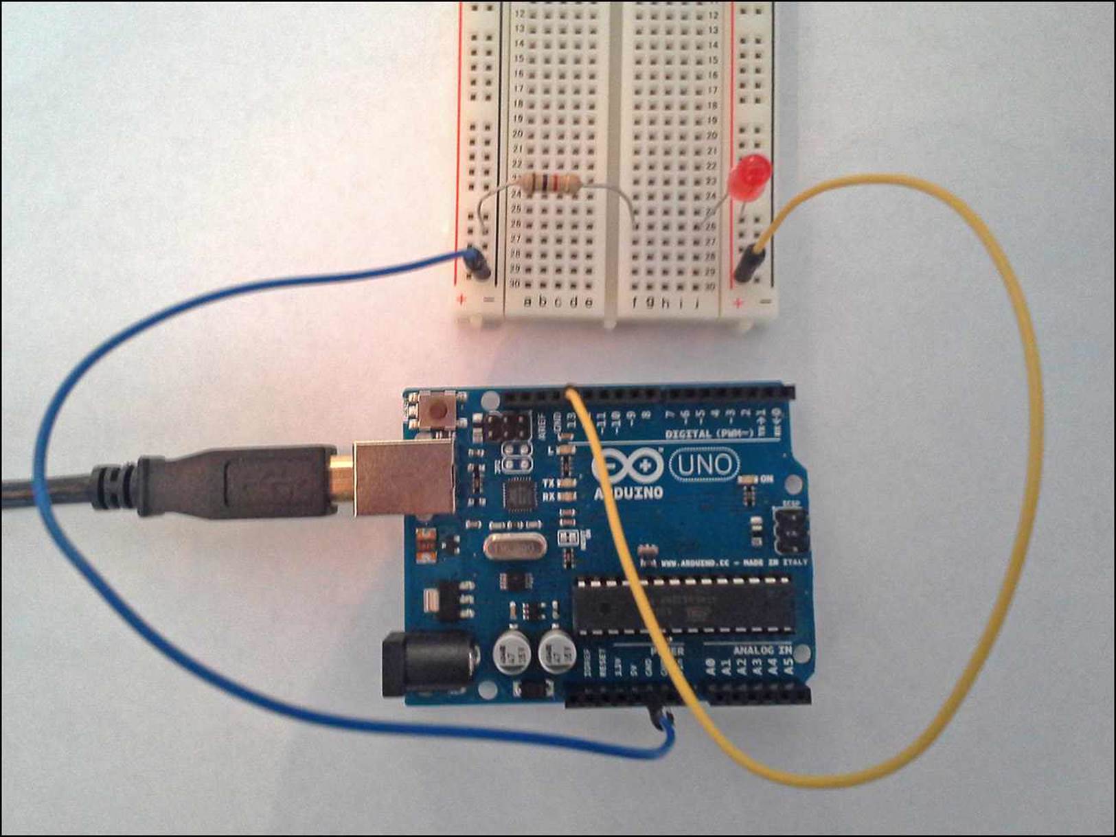
FIGURE 4.7 Circuit diagram for the sample project.
Just follow these steps to create your electronic circuit for the project.
![]() Try It Yourself: Creating the Electronic Circuit
Try It Yourself: Creating the Electronic Circuit
1. Connect a jumper wire from one of the GND socket ports on the Arduino to a socket row on the breadboard.
2. Connect a jumper wire from the digital pin 13 socket port on the Arduino to another socket row on the breadboard (not the same as the one you used for the GND signal).
3. Plug the LED into the breadboard so that the longer lead of the LED is connected to the same socket row as the digital pin 13 wire and so that the other lead is plugged into a separate socket row on the breadboard.
Caution: Polarity in Electronic Circuits
While plugging the LED in the wrong way won’t harm the LED, there are other electronic components that can cause damage if plugged in the wrong way (such as transistors). Be careful when working with electronic components that have polarity requirements!
4. Plug the resistor so that one lead connects to the same socket row as the short lead of the LED and so that the other lead connects to the socket row that carries the Arduino GND signal.
Now you should be ready to test things out. Power up the Arduino, either by connecting it to the USB port of your workstation or by connecting it to an external power source. Because the Arduino maintains the sketch in flash memory, you don’t need to reload your sketch; it should start running automatically.
Caution: Providing Power to the Arduino
Be careful when plugging and unplugging your Arduino if you’re using a USB hub with other devices. Stray voltages can result that may damage the other USB devices on the hub. It’s always a good idea to power down your USB hub when plugging and unplugging the Arduino.
If things are working, you should see the LED on the breadboard blink once per second. If not, double-check your wiring to ensure that you have everything plugged together correctly on the breadboard and that the wires are plugged into the proper socket ports on the Arduino.
Tip: Using the Serial Monitor
If you connected the Arduino to the USB port on your workstation, you can still use the serial monitor in the Arduino IDE to view the output from the sketch. However, if you use an external power source to power the Arduino, you won’t be able to view that output unless you connect an external serial device to the Arduino serial ports, which are digital ports 0 and 1 in the header sockets.
Summary
This hour walked you through your first Arduino project. First, we entered the sketch code into the Arduino IDE editor window, then we compiled the sketch, and finally, we uploaded the compiled sketch to the Arduino. You also saw how to use the serial monitor feature in the Arduino IDE to monitor output from your sketch. After that, you learned how to set up an external electronic circuit and interface it with your Arduino.
In the next hour, we take a closer look at the actual Arduino sketch code that we’ll be using in our projects. You’ll learn how the Arduino programming language stores and manipulates data within our sketches.
Workshop
Quiz
1. Which function must your Arduino sketch define to run the main part of your program code?
A. setup
B. loop
C. main
D. start
2. The Arduino IDE editor uses the same text color code to indicate functions as it does regular text in the code. True or false?
3. How do you interface external electronic circuits to your Arduino?
Answers
1. B. The loop function contains the sketch code that continually runs while the Arduino unit is powered on. This is where you need to place your main sketch code.
2. False. The Arduino IDE uses brown to indicate functions used in the sketch code, and uses blue to indicate text strings contained in the sketch code.
3. The Arduino header sockets are designed to easily interface external electronic circuits with the analog and digital input and output pins on the microcontroller.
Q&A
Q. Is there a limit to the size of the sketches I can upload to my Arduino?
A. Yes, the size of the sketch is limited by the amount of flash memory present on your Arduino. The Arduino Uno R3 has 32KB of flash memory. When you compile your sketch, the Arduino IDE console window will display the size of the compiled sketch code and how much space is remaining in the flash memory.
Q. Can I damage my Arduino by plugging in the wrong wires to the wrong header socket ports?
A. Yes, it’s possible, but the Arduino does contain some basic protections. The Arduino is designed with some basic voltage protection on each of the input and output ports. If you supply too large of voltages to the ports, however, you can risk burning out the microcontroller chip. Use caution when connecting wires to the Arduino header sockets, and always double-check your work before turning on the power.
Q. Is there an easy way to identify resistor values when working with electronic circuits?
A. Yes, all resistor manufacturers use a standard resistor color code. The resistor value and tolerance are indicated by color bands around the resistor. To find the value of a resistor, refer to a resistor color-code chart, as shown in the Wikipedia article on electronic color codes (http://en.wikipedia.org/wiki/Electronic_color_code).
All materials on the site are licensed Creative Commons Attribution-Sharealike 3.0 Unported CC BY-SA 3.0 & GNU Free Documentation License (GFDL)
If you are the copyright holder of any material contained on our site and intend to remove it, please contact our site administrator for approval.
© 2016-2026 All site design rights belong to S.Y.A.