Beginning Arduino Programming (Technology in Action) (2011)
Chapter 2. Sketching in Code
In the last chapter, we managed to get our first sketch up and running with the famous Blink sketch, otherwise known as the “Hello world” example. This is often a good place to start because it has a longstanding tradition as the first program to write when learning a new language. In the case of programming hardware, we generally use the LED to blink hello. While that is a good beginning, we want to quickly get to some of the more interesting aspects of Arduino C, beginning with the focus of this chapter: the fundamental mechanics and control structures of sketching Arduino code. Our first project, RGB Blink, will explore the basic structure, syntax, and functions necessary for controlling the output of a three-color LED, taking our blinking LED to the next level.
We'll start with a primer on what sketching means and how we can put the philosophy of sketching in code to use. As we will do throughout this book, we will then jump right into our project example and once you have this project wired up and the sketch uploaded to your Arduino board, we'll back up and further explain how the sketch works and discuss most of the elements used in the project. In this way, when we look at each of the individual concepts in the chapter, you'll already know how they were put to use. In this chapter, we'll have a look at the basic anatomy of our project sketch and discuss how and why Arduino C does what it does. Don't worry if it doesn't make a tremendous amount of sense in the beginning, just work through it and it should get clearer as you go along.
What's needed for this chapter:
• Arduino Uno
• 5mm RGB LED with common cathode
• 1x 330 ohm and 2x 220 ohm У watt resistors or similar
• Hookup wires
• Solderless breadboard
What is Sketching in Code?
The idea of sketching in code is a way of thinking about writing code as a simple intuitive process, just like drawing in a sketchbook. In this way, an Arduino program is called a sketch and is saved in a folder called a sketchbook. Sketching means we can get our hands dirty and quickly try out a new idea. It is a skill available to all of us, not just artists and designers, and neither is it limited to pens, paper, pencils, or napkins.
So often, an idea in one of my classes begins with the simple words, “Wouldn't it be cool if ...?” Quickly sketching out these ideas serves as a way to conceptualize this moment of inspiration. Writing code can be just like this; it is after all a creative process used to solve specific problems. Sketching implies a sense of directness in the application of materials, like a pencil to a piece of paper. The Arduino development environment takes this same approach to making code as simple and direct as is possible.
It is also why we will begin with simple sketches that quickly get you making something right away rather than bogging down in page after page of complex theory or algorithms.
When sketching in code, it's okay to write bad code. You won't hurt anything. As long as you get in there and start somewhere, as doing anything is always better than doing nothing. Making mistakes and learning what does work and what doesn't, is an important part of learning anything new. In our sketchbook, we will start with simple source code, the basic instructions that tell the Arduino what it should do, along with basic hardware, starting small and working our way through to more involved examples.
You should freely experiment with every example, changing values, and piecing things together in unexpected ways to see what happens. Don't be discouraged if it doesn't work the first time; stick with it and it will get clearer with time. Testing and iterations are important parts of successfully writing code. So, change existing code or write some new code to establish a basic framework and then verify that your changes compile correctly. Work in incremental steps one addition at a time as you add to this basic framework for your code so that when you finally have something substantial, you can load it on to the interface board to see what happens. If something didn't quite work as expected, all you need to do is undo that last incremental step. In this way it's a good idea when you make changes, to only change one thing at a time before verifying that it still works before moving on to the next change.
Project 1: RGB Blink
To really get started, we are going to use a nifty little component called a red-green-blue light emitting diode, or more simply an RGB LED. The RGB LED works off a similar principle as televisions and computer monitors. By using the same three colors of light that we are receptive to in our vision— specifically red, green, and blue—we can reproduce a vast array of colors through an additive colormixing process. This form of color mixing should sound familiar from secondary school science, and is shown in the RGB color wheel in Figure 2-1. While it's a little harder to make out in a black-and-white book like this one, if you use your imagination you'll see that by combining two primary colors we end up with a secondary color. For example, add the color red to blue and we get magenta or if we add red and green we will get yellow. If we add all three primary colors together we will end up with white light.
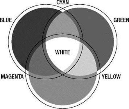
RED
Figure 2-1. RGB color wheel
The particular LED we will be using is actually three separate LEDs—in the three primary colors of red, green, and blue—in one component package. Additionally, this LED is a common cathode type, meaning that the three LEDs share a common cathode pin, or connection to ground. This pin is the longest of the four pins coming out of the LED. We will connect each of the other three pins to the Arduino board through current limiting resistors, using hookup wires and a solderless breadboard.
To get an approximately equal or balanced output from each LED, we will use a 330 ohm resistor (ohm is a unit of measurement for resistance) connected to the red LED, or leg 1 of the RGB LED, and 220 ohm resistors to the other two, legs 3 and 4. If you don't have these resistors on hand, you can use the values 100 and 150 ohm or others that are close enough in value, anywhere between 100 ohms and 1 kilohm. If you use the same values for each color that's okay too, but each color's brightness might not be as closely matched. Some RGB LEDs are different from others so double-check the data sheet or product description as your mileage may vary. Refer to the following schematic and illustration for how to wire up this circuit.
Hooking It Up
For the projects in this book, we will follow a couple of diagrams that show in different ways how the hardware goes together. We begin with a schematic, like the one in Figure 2-2, which is basically a simple drawing that shows in the most direct way possible how to make a circuit with lines that connect simple, abstracted symbols for the electrical components. Where things get placed in a schematic is rarely where they end up in our actual physical circuit—it's just a way to show how one thing connects to another. Because schematics can be rather abstract, we will also include an illustration, like the one in Figure 2-3, showing one way that the finished circuit might look on the breadboard and how it connects to the Arduino board.
■ Note To find out more information on prototyping circuits, including how to read schematics and the symbols for different components, check out Chapter 12 later in this book.
1234
1- RED
2- GROUND
3- BLUE
4- GREEN
PIN 11
LED2 GND
Figure 2-2. RGB Blink schematic
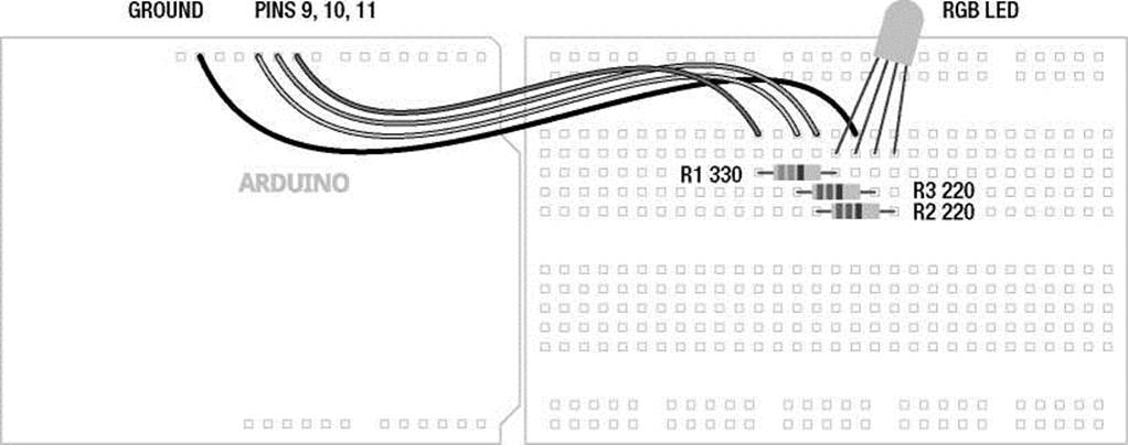
Figure 2-3. RGB Blink illustration
Uploading the Source Code
To get this circuit working, and to give us something to discuss, we are going to start with a simple sketch to change the color of our RGB LED from red to green to blue, continuously every second. If you look back to the Blink example from the last chapter, the code in Listing 2-1 should look fairly similar. Fundamentally, we are moving from using one LED to using three, turning each one on and off in a particular order. Once we start to understand this example, we will revisit it again with some more complex code.
Listing 2-1. RGB Blink Source Code /* Project 1: RGB Blinky
Uses a single RGB LED to cycle through three colors.
*/ void setup() {
pinMode(9, OUTPUT); // sets digital pins as outputs pinMode(10, OUTPUT); pinMode(11, OUTPUT);
}
// turns on red // turns off blue // waits for 1 second // turns on green // turns off red // waits for 1 second // turns on blue // turns off green // waits for 1 second
void loop() { digitalWrite(9, HIGH); digitalWrite(11, LOW); delay(1000); digitalWrite(10, HIGH); digitalWrite(9, LOW); delay(1000); digitalWrite(11, HIGH); digitalWrite(10, LOW); delay(1000);
}
Source Code Summary
Our first project sketch takes the Blink example that we uploaded in the first chapter and builds on it by adding the additional two colors available in our RGB LED, connected to pins 9, 10, and 11 rather than the built-in LED on pin 13, to blink each of the three colors in turn. As I will explain in this chapter, there are two groups of code in this sketch called functions grouped by matching curly braces, { }, each named setup() and loop()—ignore the keyword void for the time being. We use setup() to configure the state of input and output pins, as well as other actions that we only need to run once. Conversely, loop() will perform whatever actions are inside of it over and over again for an eternity, assuming limitless power as a prerequisite. Each line of code is executed inside a function, in order, from the top to the bottom. Inside the loop() function, when the last line of code is reached the function will repeat, beginning again with the first line of the loop() function.
Inside of each of these functions are statements that can include calls to other functions, such as pinMode(), digitalWrite(), and delay(). The function pinMode() is used to set a specific pin to either INPUT or OUTPUT. digitalWrite() is used to set the state of an output pin to HIGH or LOW, effectively used here to turn on or off an LED. The last function, delay(), does as it's named and delays the program for a specified number of milliseconds. We will spend the rest of our time together looking at these and other functions and statements that we will use when writing code for the Arduino platform, but first let's start with the basic structure of Arduino C.
The Structure of Arduino C
Our first project will provide an interesting backdrop for understanding what's going on with the basic structure of programming an Arduino sketch. This section will attempt to explain some of the larger points of how sketches are organized and generally work and will apply to every sketch that we might write, not just our previous example. We will get to more on the specifics of functions and statements, including their syntax and parameters, a little later.
To begin with, Arduino C follows a set of rules that govern syntax and structure and tell the interface board what to do. Some of these rules are inherited from C and others have been put into place by the Arduino development team to simplify usage for beginners. C is a top-down structural programming language, meaning that lines of code are executed in order from the top of the program until it reaches the end at the bottom. We will adopt this top-down method in our analysis of the sketch for Project 1 to discuss the major points of the Arduino programming syntax and structure, beginning with our first lines of code.
Using Comments
Looking at our first example, the first three lines contain a small descriptive block of text that we refer to as comments. Comments are areas of text that are ignored by the compiler, but provide useful notes and documentation that give us a little extra information about the sketch to make the code easier to understand for us humans. Use them to provide information about the project that the sketch is written for, about what certain variables do, what information a function needs to work properly, or what will happen if some part of the code is changed. Because comments take up no memory space on the Arduino board, they should be used generously throughout your sketch and are one of those good habits to have that should be adopted early on. Other people, including your future self, will be happy and thank you. Here's our example:
/* Project 1: RGB Blinky
Uses a single RGB LED to cycle through three colors.
*/
This is an example of block comments. Anything in between the characters /* and */ are completely ignored and do not affect the outcome of the program. Block comments can be stretched across multiple lines, creating blocks of information, but need to be balanced with /* at the beginning to tell the compiler to ignore the following text until the compiler reaches the closing characters, */. The Arduino development environment conveniently changes comments to a grey color once they have been properly registered. This lets you know that you have entered comments properly or that you still need to close block comments (because your entire sketch suddenly became grey).
In addition to block comments, a second similar form of comments, called line comments, are used throughout the example sketch. Line comments are any line of text that begin with the characters // and automatically end with the next line of code. Unlike block comments, line comments do not need closing characters and are often used at the end of a statement to provide a little more information about what that line does. This is the case in our first line comment in the previous example, as follows:
// sets digital pins as outputs
Both types of comments are also pretty useful for disabling parts of a sketch for testing and debugging. Just “comment out” an offending line to see what happens in your code. It's also helpful to make a change in a part of the code but leave the old code in place using comments just in case you want to go back to it later. Take for example the following line:
digitalWrite(10, HIGH);
This statement could be disabled or otherwise ignored without deleting the line, by adding line comments in front of the statement as follows:
// digitalWrite(10, HIGH);
Alternatively, although not necessarily any clearer, the value could be changed using the following method:
digitalWrite(l3 /*10*/, HIGH);
In this example, the value 10 is made into a comment using block comments in the middle of the line, and is, therefore, ignored by the compiler, but leaves it behind just in case you forget the old value. Once the integer value 10 has been hidden from the compiler, the integer 13 will become the new value for this statement. Keep in mind that whenever a section of code is commented out, it will only take effect the next time the sketch is uploaded to the Arduino board.
Line comments work for disabling single lines of code, but it would begin to be quite tedious to place line comments at the beginning of every line in a large block of code that needed to be temporarily ignored. Instead, place block comments around the whole section to be ignored, with /* at the beginning and */ at the end of the block of code to make the compiler ignore it.
■ Note This won’t work if somewhere in your block of code you have another set of block comments, as it is not possible to nest block comments inside of one another. In this case, you might have to change the inner block comments to line comments or make some other modifications.
Comments are tremendously useful to the programmer and anyone reading your code, but they can sometimes get in the way, especially if you're trying to write a book. For this reason, after our initial project here, we will no longer comment our code on a line-by-line basis. Yes, that may sound a little like, “do as I say, not as I do,” but I hope that it will make the discussion about particular concepts that much clearer without the added verbiage. If necessary to unpack a tricky line, we might add them in there for extra clarity.
Basic Functions
The C programming language is broken down into blocks of code called functions that form the main building blocks of any program. In this project we have two functions, setup() and loop (), each containing statements that do specific actions performed in order from top to bottom. As a requirement of the Arduino library, every sketch must at the very least contain both a setup() and loop() function in order to operate, even if they are empty. The following is technically a complete and working Arduino sketch, although it doesn't do much:
void setup() {
}
void loop() {
}
While we can and will create our own functions later in the book to handle certain tasks or consolidate blocks of code, if we intend to use one of these two functions we would need to use both of them. Since empty functions are rather boring, let's look at the following setup() function from our first project example:
void setup() { pinMode(9, OUTPUT); pinMode(l0, OUTPUT); pinMode(ll, OUTPUT);
}
Starting at the beginning, we specify the function's data type, in this case void, which is not terribly important for the moment, followed by the function's name, setup, an opening and closing parenthesis,
( ), and a block of code bounded on either side with opening and closing curly braces, { }. The three lines of code inside the curly braces are examples of statements used to set up the state of the digital pins on the Arduino interface board. Specifically, we're telling the Arduino that pins 9, 10, and 11 should be used as outputs and that we intend to use them a little later on in the sketch.
Of these two functions, the setup() function is called only once at the beginning of our sketch and is used for setting up various aspects of the Arduino board for running our code. A function call is another way of saying that the function, and all of the functions contained within it, is executed in the order they are listed. Examples of using the setup() function might also include establishing serial communications, making initial sensor readings, or running certain tasks that are only needed one time. This function will always run once, immediately after powering up or resetting the Arduino board.
■ Note Anytime we discuss a function in this book, we will use a pair of parenthesis after its name to help distinguish functions from things like variables. As an example, assignValue refers to a variable (more on these in a moment) where assignValue() refers to a function call.
The second function, loop(), makes it possible for your sketch to run continuously, and begins after the last statement in the setup() function has finished executing. Once the Arduino has completed its statements in order, reaching the end of the statements in the loop() function, it will, appropriately enough, loop back to the top of the loop() function and begin again, ad infinitum. Chances are this is where the bulk of your Arduino sketches will reside. Later in this book, we will investigate ways to manipulate the flow of the program and even demonstrate some methods for bouncing information back and forth between functions of your own creation.
■ Note When the Arduino runs a sketch, it starts at the top and works its way towards the bottom. This is called program flow and refers to the order that the statements are executed. Much like the way the loop() function continuously repeats when it reaches the end of its statements, there are other ways to modify the program flow, which will be discussed later.
Statements and Syntax
As mentioned earlier, nestled inside the curly braces of functions are lines of code called statements. Quite simply, these are the parts of the sketch that actually do something, such as calls to other functions, including those functions that are a part of the standard Arduino library, declaring and assigning values to variables, or performing arithmetic operations or comparisons. In our first project, anything in between the curly braces { } is a statement; take the following, for example:
digitalWrite(9, HIGH);
This line of code is a statement that calls one of the Arduino library's built-in functions named digitalWrite(), which is used to turn on or off one of the Arduino digital pins previously configured as an output. We pass this function two pieces of information that it needs to do its job: the number of the pin and the state that we want the pin to be in. These additional parameters, specific to each function, are called arguments and are found inside the left and right parenthesis, with multiple arguments separated by commas. In this example, we are telling the Arduino environment to turn on digital pin 9 of the Arduino interface board, as explained later.
There are two kinds of statements used in programming C: simple statements, including the most recent example, as well as compound statements. Simple statements include function calls, such as our earlier call to digitalWrite(), assignment statements, and arithmetic operations and are always terminated with a semicolon. Semicolons ( ; ) are used to separate one simple statement from another so that the development environment can tell them apart. Forgetting to end a simple statement with a semicolon will result in one of the most common errors in the Arduino development environment. The following are a few examples of simple statements:
delay(l000); digitalWrite(ll, HIGH); int myValue = 0; myValue = 150 + 150;
Compound statements are made up of several lines of code that include other statements. Functions, such as setup() and loop(), are in effect compound statements. The if statement, covered in greater detail later in this book, is another form of a compound statement. A common example of the if statement would look like the following:
if (pin2 == HIGH) { digitalWrite(13, HIGH);
}
This statement will check the condition of the variable pin2 and will perform the following enclosed statements, to turn pin 13 on, if the variable meets the defined condition, in this case if the state of pin 2 is equal to HIGH. In this example, we see that compound statements use curly braces, { }, to enclose one or more statements within it, creating a continuous block of code. Curly braces must be used in matching pairs and can encompass as many other statements, both simple and compound, as necessary.
While our example works fine, curly braces are only really needed by the structure of multi-line compound statements. If, as in the most recent example, the conditional statement only includes one other simple statement, the complex statement could be rewritten as a simple statement by removing the curly braces, as in the following syntax:
if (pin2 == HIGH) digitalWrite(13, HIGH);
This example is functionally the same as the one prior to it, although it saves us some real estate on our screen and debatably makes the code easier to read. To say it another way, curly braces are useful for enclosing multiple statements in one continuous block of code, creating a compound statement while simple statements use the semicolon at the end of each single line. Remember that simple statements inside of compound statements still need to end with semicolons.
In these examples, you have also seen the application of the parenthesis, ( ), to enclose arguments in a function or, as we will later see in more depth, for isolating arithmetic and comparison operations. Parentheses are used in pairs, so don't forget to close them off. The loop() function has nothing inside its parenthesis because no data is being passed to or from the function (more on this later). On the other hand, the example of digitalWrite(9, HIGH) passes two values to and from the digitalWrite() function, in this case the physical pin number on the interface board and its condition assignment. We have also used the parenthesis in separating a comparison operation in the case of if (pin2 == HIGH) where we are testing the condition of pin2 against the constant HIGH. In arithmetic, parenthesis are also used to alter the order of operations as in (2 +2) * 10, although we will get to comparison and arithmetic operations in more detail momentarily.
Verifying and Uploading
Taking this concept of sketching to heart by tossing together some lines of code that we are still not fully up to speed on, we've got a sketch entered into the Arduino development environment and we think we have all the syntax and statements correct, but now what? In the last chapter, we blindy uploaded our first sketch full of confidence, but how do we know if the code we entered will work or not before uploading it to the Arduino board? To answer these questions, let's revisit uploading our sketch to the Arduino board, looking a little closer at the verifying and uploading process, including how to save your sketches and some of the common errors we might run into.
Verifying
As mentioned earlier, it is always a good idea to periodically verify a sketch that you're working on, just to make sure that you're on the right track, and even though this happens automatically before uploading a sketch to the Arduino board, it's a good idea to verify before uploading. To verify our code is to check that our code is correct and follows all the right syntactical rules that our sketches need to follow. We verify our sketch by hitting the Verify button in the top left of the toolbar in the Arduino development environment, as shown in Figure 2-4.
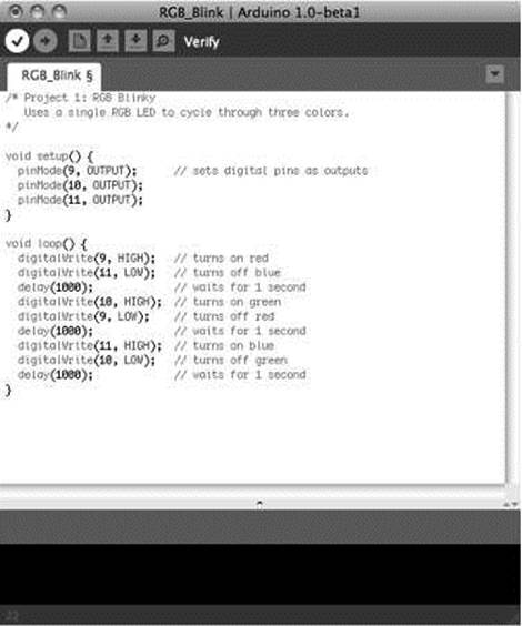
Figure 2-4. Verifying/compiling
Verifying will run the sketch through a process called compiling, where the development environment takes the Arduino C code that we have written and translates it into a binary format that the actual microcontroller will understand. If all goes well, a note will appear at the bottom of the window that says, “Done compiling,” and you will be told the binary sketch size in bytes. If there is an error during the verification process, skip ahead and check out the section on common errors to see if you can figure out what went wrong. Once we have completed writing our sketch, verified it for errors, and everything completes successfully, we are ready to upload the sketch to the Arduino board; but before we do that, let's save our hard work.
Saving
Once you've got a working sketch that is ready to be uploaded to your Arduino board, or even if it is still in-progress, you should probably save your file frequently. To save a sketch, all we need to do is hit the Save button in the toolbar, as shown in Figure 2-5.
®օո
RGB_Blink I Arduino l.O-betal
□ Save
/* Project 1: RGB Вlinky
Uses a single RGB LED to cycle through three colors.
*/
void setup() { pinMode(9, OUTPUT); pinMode(10, OUTPUT); pinMode(ll, OUTPUT);
>
void loop() { digitalWrite(9, HIGH); digitalWrite(ll, LOW); delay(1000); digitalWrite(10, HIGH); digitalWrite(9, LOW); delay(1000); digitalWrite(ll, HIGH); digitalWrite(10, LOW); delay(1000);
>
// sets digital pins as outputs
// turns on red // turns off blue // waits for 1 second // turns on green // turns off red // waits for 1 second // turns on blue // turns off green // waits for 1 second
|
Binary sketch |
: 1070 bytes (of a 32256 byte maximum) |
|
|
7 |
Figure 2-5. Saving
The Arduino development environment saves files in the default sketchbook folder named Arduino, usually found in your Documents folder. Sketch names must contain standard characters and numbers, however, they cannot begin with a number and cannot include a space character. Instead of spaces, we generally use the underscore ( _ ) to separate words in a file name. The development environment also stores the file in a folder of the same name that it will automatically generate if the folder is not already there. Once saved, we can access our sketch from the File > Sketchbook menu.
Uploading
Once our sketch is successfully compiled and has been safely stored in our sketchbook, we are ready to upload our sketch to the Arduino board by hitting the Upload button in the toolbar, shown in Figure 2-6.
RGB_Blink I Arduino l.O-betal
ooDDDE Upload
/* Project 1: RGB Вlinky
Uses a single RGB LED to cycle through three colors.
*/
// sets digital pins as outputs
void setup() { pinMode(9, OUTPUT); pinModegjl0, 0UTPUT)|; pinMode(ll, OUTPUT);
>
// turns on red // turns off blue // waits for 1 second // turns on green // turns off red // waits for 1 second // turns on blue // turns off green // waits for 1 second
void loop() { digitalWrite(9, HIGH); digitalWrite(ll, LOW); delay(1000); digitalWrite(10, HIGH); digitalWrite(9, LOW); delay(1000); digitalWrite(ll, HIGH); digitalWrite(10, LOW); delay(1000);
>
|
Binary sketch |
: 1070 bytes (of a 32256 byte maximum) |
|
|
7 |
Figure 2-6. Uploading
Pressing the Upload button will send a signal to the Arduino microcontroller that tells it that it needs to stop what it's doing and pay attention to the incoming code. At this point the LEDs marked RX/TX on the interface board will blink like mad, indicating that the code is being transferred to the board using serial communications through the transmitting (TX) and receiving (RX) of data using the built-in USB to Serial converter. When all is said and done, the notice bar will tell you when the upload is complete and your sketch will begin running momentarily.
Common Errors
You've just punched in your new sketch with eager anticipation to see that LED blink. You hit the Verify button, and after a long second or two, an error pops up. Now what?
If things didn't go as planned because of a compiler error, the notice bar will turn orange and sometimes give you a cryptic form of message, as seen in Figure 2-7, that basically tells you to go back and fix something.
RGB_Blink I Arduino l.O-betal
ooBDDQ
/* Project 1: RGB Вlinky
Uses a single RGB LED to cycle through three colors.
// sets digital pins as outputs
void setup() { pinMode(9, OUTPUT); pinHode(10, OUTPUT)
// turns on red // turns off blue // waits for 1 second // turns on green // turns off red // waits for 1 second // turns on blue // turns off green // waits for 1 second
void loop() { digitalWrite(9, HIGH); digitalWrite(ll, LOW); delay(1000); digitalWrite(10, HIGH); digitalWrite(9, LOW); delay(1000); digitalWrite(ll, HIGH); digitalWrite(10, LOW); delay(1000);
>
expected before 'pinMode'
RGB_BTink.cpp: In function 'void setupC)': RGB_BTink:7: error: expected ՝;' before 'pinMode'
Figure 2-7. Compiler error
This can be a little disappointing at first, but hang in there, I'm sure you'll figure it out. There are two general types of errors that we should be concerned with: hardware and syntax. Coming up are steps for troubleshooting these various error codes to help you get going again.
General hardware errors occur because something does not match the hardware you have or a connection isn't made correctly, as in the following example errors:
Serial port not found.
Problem uploading to board.
First, check that your board is connected to your computer and is indicating good power with a lit LED marked ON. With this verified, next check that the correct serial port and the proper board type have both been selected under the Tools menu. If the USB cable is not connected or the wrong serial port has been selected, the development environment will offer to connect using a different serial port. Sometimes a more serious hardware failure will generate similar errors and you will need to talk to your reseller to iron these problems out.
Other types of hardware errors might show up as something not working the way you think it should because of a bad connection. In our example project, you would expect the LED to first blink red, then green, and then blue; but yours doesn't light up red for some reason. This type of error comes from not wiring the components correctly, reversing the direction of certain parts like LEDs, or having the wires go to the wrong pins. This can be easily fixed by carefully going back over the hardware circuit, as shown in the schematic and illustration, to find out where something went wrong. It's even a good idea to have another pair of eyes look over it just in case they see something that you missed.
The second category of common errors are syntactical errors where you missed a semicolon, parenthesis, curly brace, or other character or form of syntax needed for the sketch to function properly, as shown in Figure 2-7 and the following examples:
expected ';' before... expected ')' before. expected '}' before.
The Arduino development environment will generally give you a pretty good idea where to look for this problem by moving the cursor near the problematic code and highlighting the code near where the error was found, so you can fix it by replacing the missing character before trying to verify the code again.
■ Note Remember that at the end of every simple statement a semicolon is needed to separate one statement from the next. Also, all parenthesis, curly braces, and block comments need to be matched in pairs.
Many syntax errors stem from Arduino C being case sensitive. In a case sensitive language, whether a letter is uppercase or lowercase must match exactly between what is entered and the syntax of the function, variable, or other statement being used. When writing Arduino sketches, there is a big difference between pinmode(), pinMode(), and PINMODE()—only one of these will actually work. The following are some examples of errors relating to case:
'pinmode' was not declared in this scope 'high' was not declared in this scope
These syntactical mistakes are examples of using the wrong case commonly when calling functions or using variables or constants. Look in the highlighted line of code for where you might have mistakenly typed high instead of HIGH, output instead of OUTPUT, pinmode instead of pinMode, or any other instances that are case sensitive.
No matter the error, just take a breath and think it through. I'm sure you will find it in no time. Writing code has a funny way of needing to be extremely logical and literal. If you are still having problems getting it going, you might turn to the generally helpful Arduino Forums at http://arduino.cc/forum.
Summary
Whew! That was a lot to get through for our first project, but we made it! We started with the philosophy of sketching in code; introduced our first project, including some diagrams and source code; discussed the structure of Arduino C, including using comments, the basics of Arduino functions, and working with statements and the elements of syntax; and then we wrapped things up by looking at compiling, saving, and uploading our sketches, as well as some common errors that might crop up once in a while.
That should have provided a nice overview of what goes into your typical Arduino sketch and given you a sense of how these various parts work together. It's really not that bad and the more you work with it, the easier it gets. Now before we get to some of the more advanced digital and analog functions available on the Arduino, we need to first cover a few more basics in the next couple of chapters. We will begin by revisiting our RGB Blink sketch from this chapter to see what we can do with it, while also talking about variables and the different kinds of data types available to us. Hang in there, I promise it'll get much more interesting once we get these basics out of the way.
All materials on the site are licensed Creative Commons Attribution-Sharealike 3.0 Unported CC BY-SA 3.0 & GNU Free Documentation License (GFDL)
If you are the copyright holder of any material contained on our site and intend to remove it, please contact our site administrator for approval.
© 2016-2026 All site design rights belong to S.Y.A.