Lightning Fast Animation in Element 3D (2014)
Chapter 3. Your First Objects
We've laid the groundwork for our project. You have your directories set up, and you're itching to start animating. Well, there's one more thing we need—something to animate! In this chapter, you're going to learn the basics of modeling in the 3D virtual space. Any modeling software can be used. The principles will be the same, but the buttons may be located in slightly different areas. The bonus is, once you know how to model, it doesn't matter what software you use; the process is the exact same. For this chapter, we're going to use Maya 2012. Again, this is not a book on 3D modeling; however, to truly understand 3D animation, a good foundation in modeling is a must. This chapter is a high-level overview of the principals and techniques on 3D modeling, not specific to a single 3D modeling software.
Primitive modeling
Primitive modeling is exactly what it sounds like. We're going to use primitive shapes (sphere, box, pyramid, torus, and cylinder) to make a more complex object.
Let's start with a cylinder to create the body of our salt shaker. In the following screenshot, you'll see that we're in the middle of creating our cylinder. You'll also notice that it looks more like an octagon than a round cylinder. That's what we're going for. You can create a hexagon, a perfectly round cylinder, and so on, by changing one parameter.
On the left side of the following screenshot, under the Create setting, we've changed our Axis Divisions to 8. This is what has made our object octagonal. If we had set it to a higher number (such as 32 or 64), we would have ended up with a much more round object. All 3D modelers have this feature; you may just have to look for it:
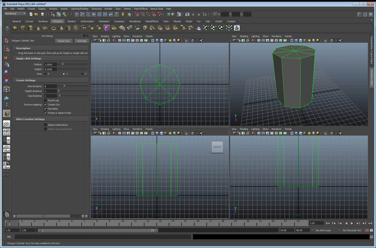
Making octagonal cylinder in Maya
Now that we've made the shell for our salt shaker, let's make it hollow (to hold some salt). When performing 3D modeling, it's actually important to change your mindset a bit. Instead of thinking of an object as a picture to draw, think of it as a ball of clay to mold. If you wanted to turn the octagonal cylinder into a container, you could use a tool to scoop sections of it out. If it were an object that is easy to vaporize (such as foam), you could use another object (such as a metal cylinder), heat it up, and burn it out. This is very similar to what we're about to do.
Booleans (cutting and molding tools)
If you're a programmer, you think of Booleans as either a true or false value. This is a completely different Boolean campared to an operation in 3D modeling. Simply put, a Boolean is a relationship between one object and another. There are four basic Boolean operations that you will find in any 3D modeling software. These are add, subtract, union, and difference. First, let's create another set of geometry to Boolean with our salt shaker. Duplicate your octagon (in Maya, simply use Ctrl + D). Scale the octagon so it's smaller in its depth and width but taller than our original geometry, and move it up slightly, as shown in following screenshot:
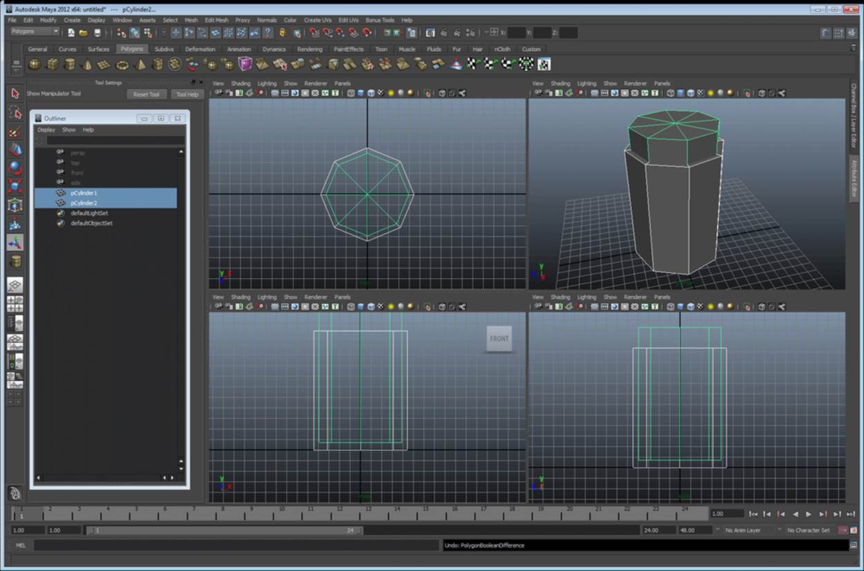
Setting up for your first Boolean
Differences between Boolean operations
Although the results may look somewhat similar between some of the Boolean operations, notice what happens to the wireframes in the following screenshot. They are vastly different. Let's cover these one at a time:
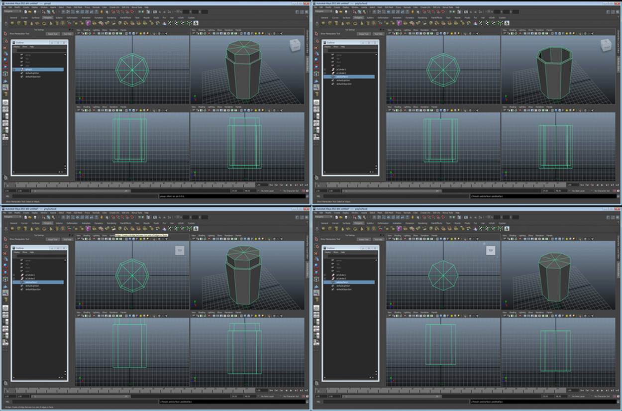
The four basic Boolean types. Top-left: add, Top-right: subtract, Bottom-left: union, Bottom-right: difference
Boolean add
Believe it or not, this feature does not exist in Maya. There is a reason for this—using a Boolean add is like using the group tool. It simply adds all the geometry together. No actual changes are made; it simply makes one object created out of two objects. The result looks like the top-left part of the preceding screenshot. All points and polygons remain intact; they are all now just part of one object instead of two objects.
Boolean subtract
A subtract operation is a lot like the vaporization tool that we mentioned previously. With this tool, you use one object to cut a shape out of another—a stencil, if you will. In some software, the original cutting tool disappears after the operation completes (as seen in Maya). The top right image of the preceding screenshot is the result of a subtract operation. This is what you will use to make the body of your salt shaker hollow (don't do this yet, we still need it whole to make our shaker top).
Boolean union
The union operation is similar to add with one major difference. The resulting object may look the same on the outside, but all of the unseen polygons and points have been removed. Now, you are left with one object, which is the result of joining two objects perfectly. In the preceding screenshot, the lower left image is the result of the union operation.
Boolean difference
A difference operation is the complete inverse of subtract. When performing the difference operation, the resulting object is only the intersection between the two objects. On the lower-right section of the preceding screenshot, you can see the result of the difference operation. Instead of cutting out the center of our octagon, we're left with an object that would plug the hole perfectly from our subtract operation.
The shaker top
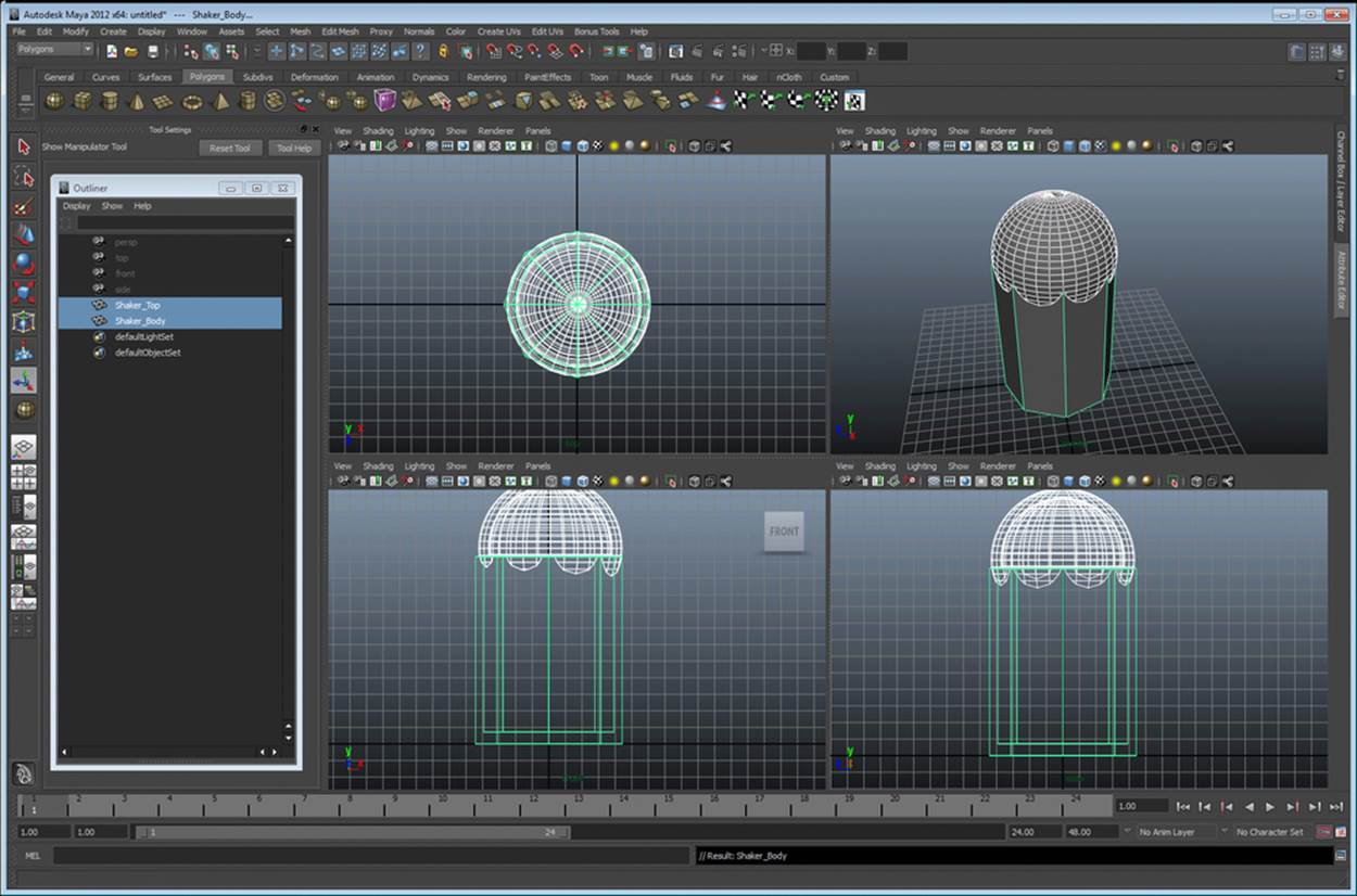
Now that you're an expert on Boolean operations, let's use them some more to create our shaker top. Create a spheroid that envelopes the top of the shaker. The result should look something like the following screenshot:
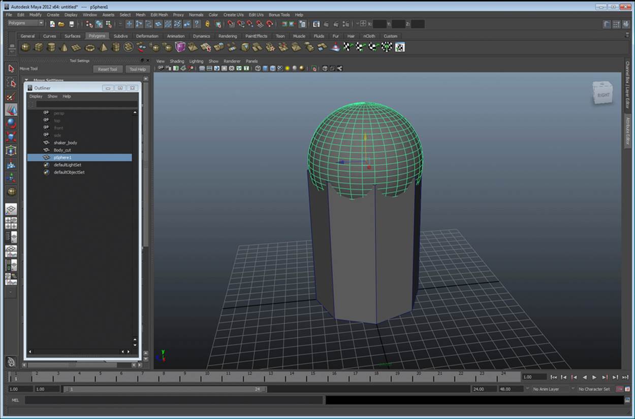
The process to create the shaker top
Let's perform the following steps that are similar to our shaker body:
1. Create a slightly smaller sphere to hollow out our top.
2. Duplicate this sphere.
3. Scale it down slightly (as shown in top-right of the preceding screenshot).
4. Now, use this sphere to perform the subtract operation on the larger sphere. (In Maya, select the larger sphere first, then the smaller sphere, and navigate to Mesh | Booleans | Difference.)
5. Now you have a hollow sphere. Next, duplicate the main shaker body shell, and use that to perform the subtract operation on the hollow sphere.
Tip
In Maya, you must delete the history from the hollow sphere first or you may have issues. This can be done by navigating to Edit | Delete by type | history, with the hollow sphere selected.
Now, let's finalize our main Boolean procedures. Go ahead and select the main shaker shell and the smaller octagon, and perform another subtract operation. If you're using Maya as your modeler, make sure you delete all your history now (by navigating to Edit |Delete all by type | history). The result should look like the following screenshot:
The results of our major Boolean operations
Okay! Our shaker looks pretty basic but it's starting to take shape. Let's put some holes on the top section using Booleans and another tool called array.
Making holes in the shaker top
So, it's pretty obvious that if we want to create holes, we're going to be using Booleans. However, how do we get a nice, even hole pattern? Well, we're going to create a bunch of cylinders for our cutting pattern using a tool called array. Let's start with a basic cylinder for our first hole. Create one that looks like the one in the top-left section of the following screenshot:
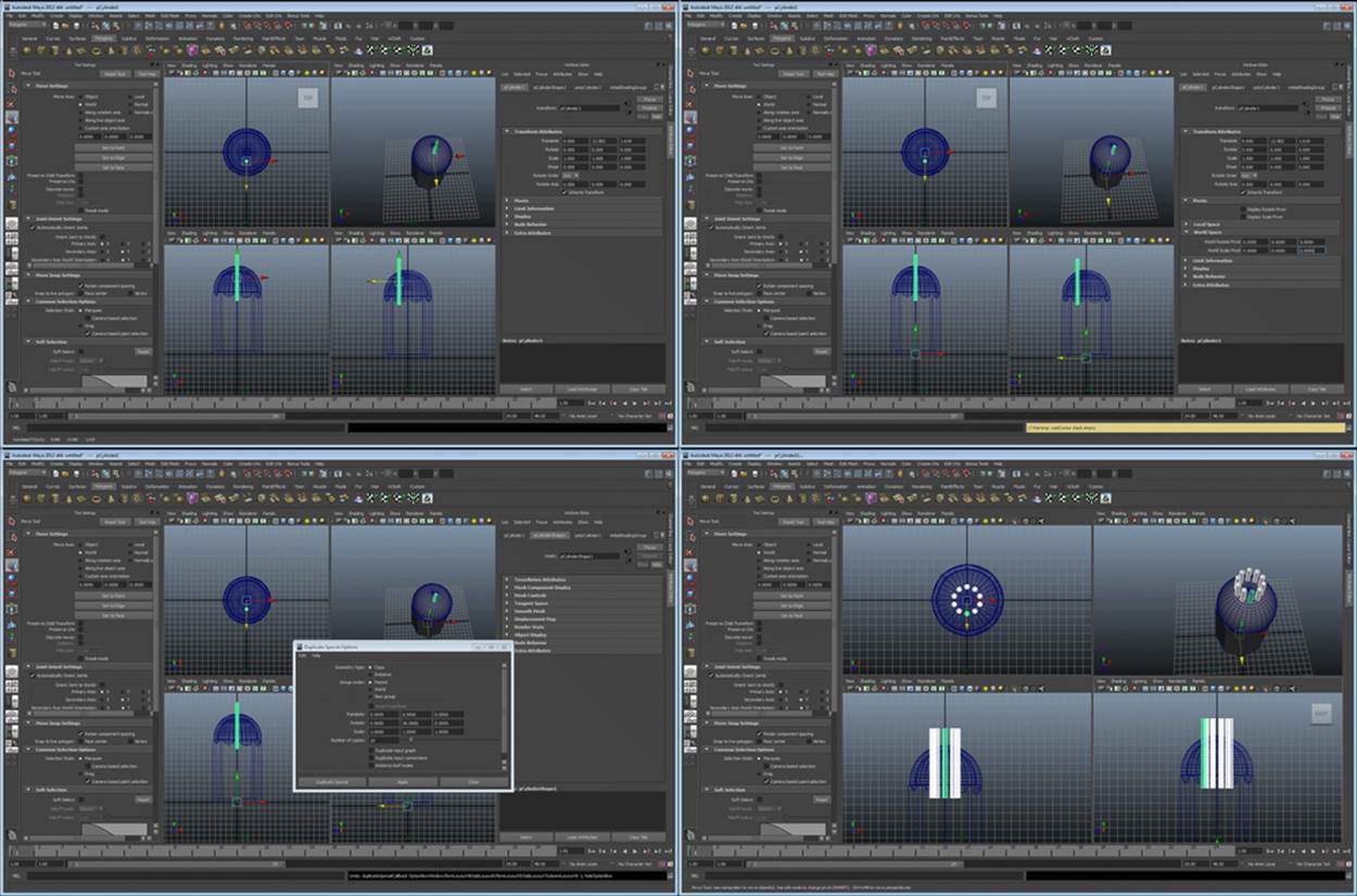
Creating the cutting tool for the holes in our shaker top
Object arrays (duplicating objects in a pattern)
In the preceding screenshot, we showed you how to create an array of cylinders as our cutting tool for the top of the salt shaker. The process is slightly different in every software package, but the principles are the same.
Now that we've created our cylinder as a template, we have to set that object's pivot point to the center of the shaker (so we have a point of reference to revolve around). In Maya, this can be done in the attribute editor (shown in preceding screenshot at the top-right). Once we've set our revolving point, we just need to duplicate the object in a round array. In Maya, this is done by using the Duplicate Special tool (Edit | Duplicate Special). Then, we set the options shown in the bottom-left section of the preceding screenshot. We want an object every 36 degrees, and as 360 divided by 36 is 10, we want 9 objects (to make them into a complete circle without duplicating the first one). We want them revolving around the y axis. The result should look like the bottom-right section of the preceding screenshot.
Now, before we cut the top of our shaker, you'll need to combine these into one object if you're using Maya (by selecting all of them and navigating to Mesh | combine), and then delete their history. Really, you should only perform a Boolean on two objects at a time. Combining all of the cylinders to one object will speed up this process. Don't forget to delete the history. Your result should look like following screenshot:
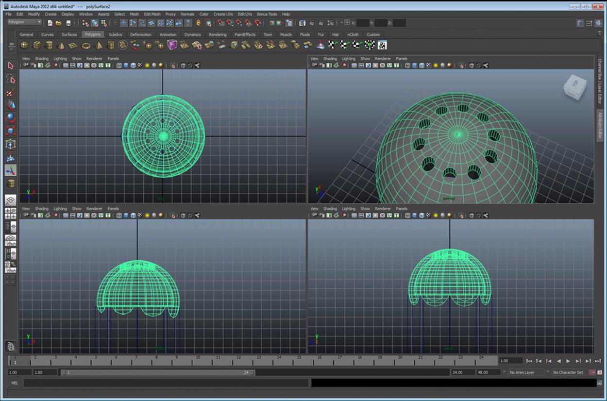
The salt shaker with holes cut in the top
Finalizing your salt shaker
We're almost there. But our shaker still looks pretty funny. Let's widen the base a bit so that our shaker looks more like a real-world salt shaker. Select the points (both inside and out) on our shaker, and scale them up until it looks decent. There, now our shaker's geometry is complete. Your finished shaker should look similar to the following screenshot. Save your object (in your software's native format for now) and let's move on to the next modeling technique:
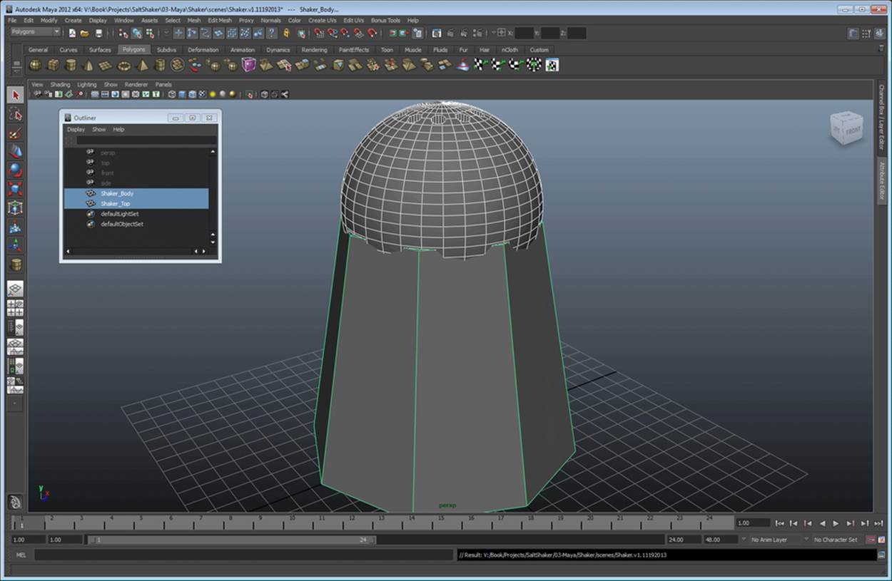
The finished salt shaker's geometry
Point modeling (the table and wine bottle)
There are several distinct styles of point modeling. For our purposes, we're going to use points to create a stencil, and then create the virtual version of a lathe to create a round object from that stencil. Let's get started…
The wine bottle
Start by creating a new scene in your modeling software (we'll come back to the shaker later). A wine bottle is smooth and kind of beautiful really. We could use primitive modelling to make one. However, it'll be much faster to create it using a curve method. Start in your orthogonal front view. Select your curve tool (in Maya, navigate to Create | CV Curve).
You'll want to create a 2D representation of half of your wine bottle. This stencil will be revolved around the y axis eventually and will create a nice round bottle. The result is the top-left and top-right of the following screenshot:
Building the wine bottle
Now that you've drawn the wine bottle, we need to make sure that the start and end points of the curve are exactly on the axis around which we intend to revolve our geometry. This will ensure that there are no strange overlaps or gaps in our geometry. Unfortunately, Maya does not have a GUI interface to parametrically edit the CV points, so we're going to use the script editor to set these points directly on the y axis.
First, open your script editor and select the CV point (pictured in the bottom-left section of the preceding screenshot). Now, enter the following code into your script editor and run it (click on the play button in the script editor):
string $selection[] = `ls -fl -sl`;
for( $vertex in $selection )
{
float $pos[] = `xform -q -ws -t $vertex`;
xform -ws -t 0 $pos[1] $pos[2] $vertex;
}
This process should be run for both the starting and ending point of the curve. This will set the x coordinate of the point to 0 and solve our revolving axis problem.
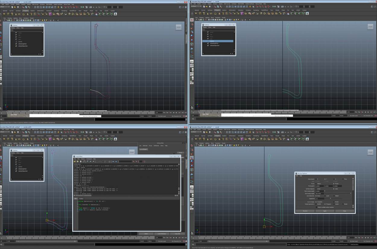
Finally, let's revolve (lathe) our wine bottle. In Maya, this tool can be located by navigating to Surfaces | Revolve. We want our pivot for the lathe process to be at the center of our world (0,0,0), have 32 sides, have output as polygons, and all should happen on the yaxis. The complete settings are visible on the bottom-right section of the preceding screenshot. Bingo! You have a classic wine bottle (shown in the following screenshot). Congratulations! You are now a lathe master. Save your wine bottle and let's move on.
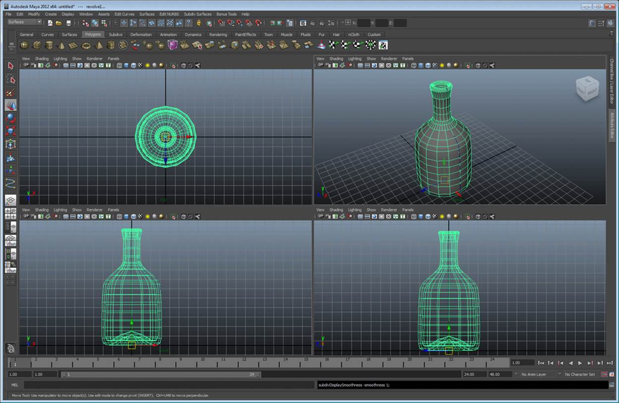
The completed wine bottle
Do it again (the table)
The process for the table is exactly the same as the process for the wine bottle. Create a curve stencil, set the origin points on the y axis, and revolve it as shown in the following screenshot:
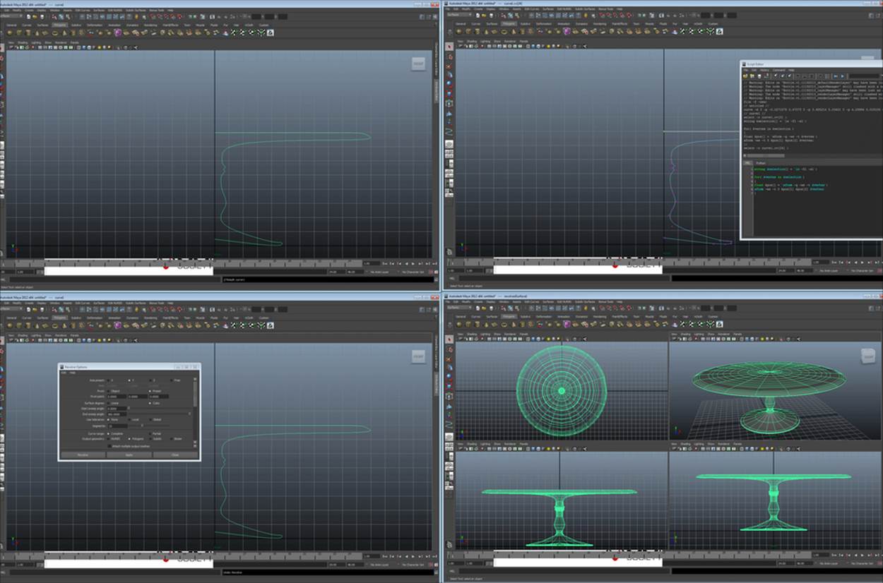
The table
Box modeling (the lamp)
Box modeling is the closest to sculpting clay out of all of these methods. It can be especially useful when creating organic shapes. It is exactly how it sounds. You start off with a box (a cube of clay, if you will) and pull it, stretch it, add on to it, and take it away to create your shape. Box modeling can be quite complex, but we'll cover the basics here.
Subdivs, metanurbs, and curved shapes
Subdivs (called metanurbs in Lightwave) are a simple way of editing shapes. If you've noticed, all shapes in 3D are essentially made of polygons. Polygons are made of straight lines to create shapes in two dimensions, and these shapes are put together into facets to create a 3D object. subdivs divide up these polygons into sub polygons to allow you to work with very complex shapes while not getting confused seeing every polygon and point in a complex object. Confused yet? You won't be by the end of this section.
The Polygon proxy mode
Starting off, let's create a subdiv cube in Maya (the other software has this feature, but for this chapter, let's stick to Maya). Use the top menus and navigate to Create | Subdiv Primitives | Cube. You should get something that looks like the top-left image of the following screenshot. Great, we've got a cube, but now we need to learn how to edit it. The easiest way is to use polygon tools in Maya on this subdiv. You can do this by entering into the Polygon proxy mode (upper-right image of the following screenshot). This will draw a polygon cage around our subdiv and give us the ability to control many polygons by using only one subdiv (polygon proxy) at a time.
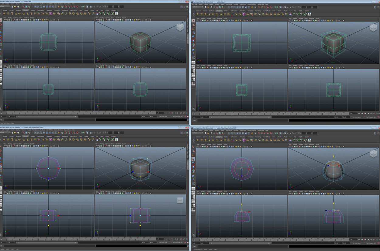
The polygon proxy mode
Extruding and editing
Extruding and editing are the keys to box modelling. There are a plethora of tools to use (splitting polygons and so on) in box modelling, but extrusion is the basis. Every time you extrude a polygon, you not only add just another face, but also the sides for that face. It's basically like adding another chunk of clay to manipulate.
If you select the faces on the bottom of the lamp and extrude them (without any movement), you'll notice that the bottom of the lamp flattens out. This is because the curves are calculated by polygon proxy density. You've just created another batch of polygons; therefore, the density is higher and the curve is sharper. So, extrusion can be used to make more defined areas, which are pictured on the top-left section of the following screenshot:
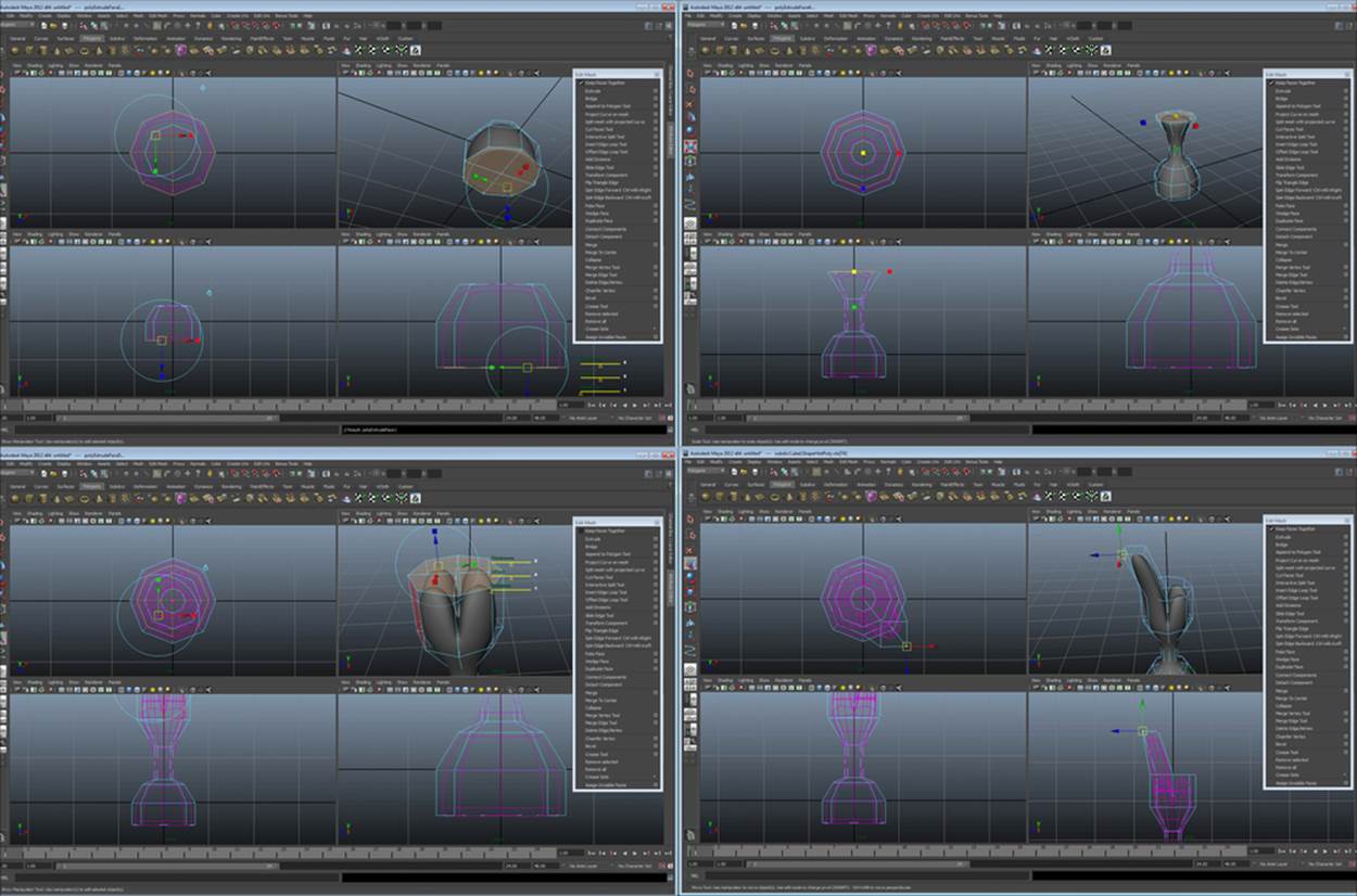
Extruding and editing part 1
If you select the faces on the top of our future lamp and extrude them, you'll see the same flattening effect. Now, move them up. It appears that you've just stretched the top of the lamp. You can size these polygons to create interesting shapes. Move them, rotate them—do anything that your imagination leads you to do (shown in the top-right section of the preceding screenshot).
Now, if you uncheck Keep Faces Together and extrude/move up again, you get a very interesting result. The lamp seems to fork off in four directions (pictured on the bottom-left section of the preceding screenshot). We can alter the points on these forks so that each fork cage has a mostly-square shape, then extrude it again (bottom-right section of the preceding screenshot). Playing around, we can create a lamp with four distinct light posts (top-right section of the following screenshot). Now if we select all four lamp stems again, we can extrude them in unison and finalize the light posts (the top-left and bottom-right sections of the following screenshot). Finally, by editing the points of the cage around the base, we can make it look like the lamp probably won't tip over (bottom-right section of the following screenshot):
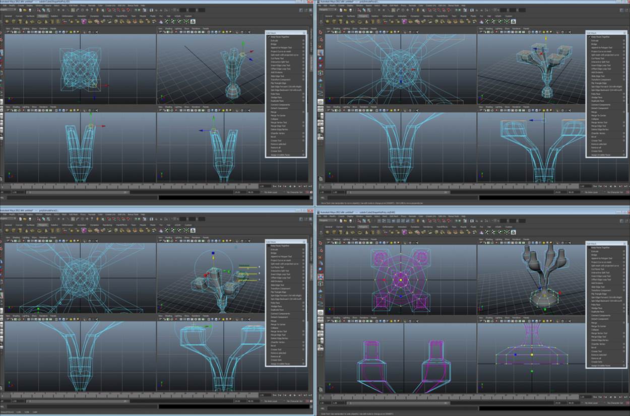
Extruding and editing part 2
We won't need to worry about light bulbs. Element 3D already has plenty of them, plus we'll be able to show you how to incorporate your models with Element 3D models using their bulbs. Congratulations, your first box model geometry is nearly complete! Save this version as Version1; now we move on to version two.
Freezing subdivs to polygons
Since we're using Element 3D (not Maya) for the end product, it's important that we avoid as many translation issues as possible. Therefore, let's get this object back into a standard format by freezing all of the subdivs into standard polygons. The first thing to do is get into the Polygon proxy mode (top-left section of the following screenshot), so let's get this object into the standard mode (shown in the top-right of the following screenshot). Perform the following steps (in Maya, this is under Subdiv Surfaces | Standard mode):
1. From Modify, we navigate to Convert | Subdivs to Polygons.
2. Set the polygon count to 2 and convert it (shown at the bottom-left of the following screenshot).
You should end up with something that looks like the bottom-right section of the following screenshot. Now you can see why it's nice to work with subdivs. Can you imagine editing all those polygons? Eek!
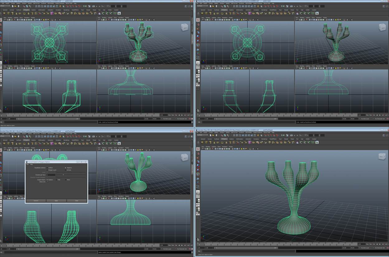
Freezing subdivs to polygons
Now, let's save this as version two of the lamp (just in case we want to edit in polygon proxy mode again later) and move on to the lamp shades. Don't open a new scene; we'll create it here with the lamp.
Incorporating multiple methods (the completed lamp)
No carpenter has only one saw. So, don't restrict yourself to only one method. Multiple methods are used for every object in the professional world. Experience will show you which methods will save you time on each section of your objects. Ask 100 different animators their favorite tools and you'll get 100 different answers. Play around and figure it out for yourself! Now, let's get these lampshades done.
First, I've hidden the lamp base (not deleted it) so I can work on the lampshade without distractions. It's not important to create a perfect lampshade off the bat. If you look at a lampshade as primitive, all you need is a basic shape that you can scale and position on the lamp.
So, we freehand a curve (the top-left section of the following screenshot), and revolve
it (top-right section of the following screenshot):
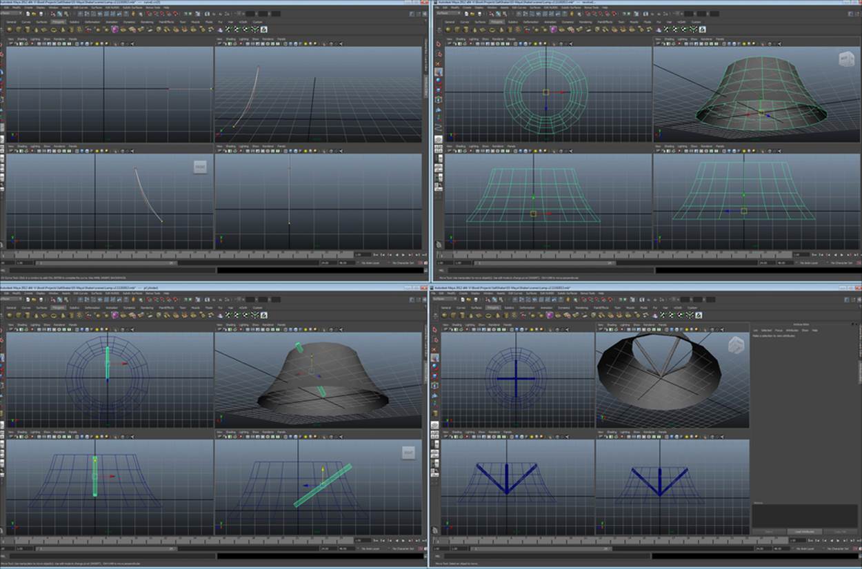
The process for making the lampshades
Then, we need some sticks to cast the shadows of the lampshade holder on the lampshade when it's lit, so we create a primitive cylinder and position it (the bottom-left section of the preceding screenshot). We then edit the cylinder to line it up with the lampshade in a better way and follow our array process to create more sticks (the bottom-right section of the preceding image). Voila! A simple lampshade is created.
Finally, we scale the lampshade and position it on our object and then duplicate and position each lampshade in its correct spot. Our lamp is finished! Save this as version three. The finished lamp will look like the following screenshot:
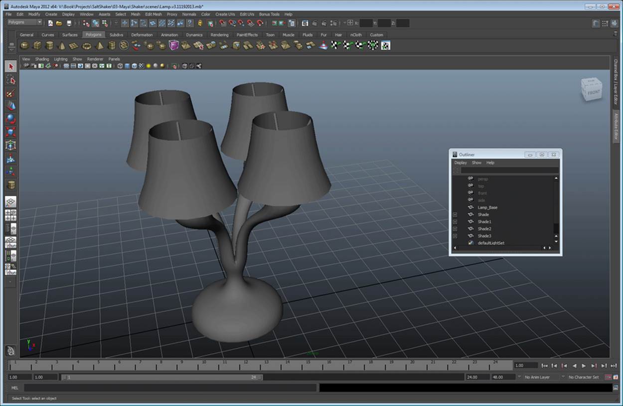
The finished lamp
Summary
Congratulations! You are now one step closer to being a "3Deity"! In this chapter, you've learned about all of the basic tools and techniques of 3D modeling. With these tools, you'll be able to create virtually any object you can imagine as you get more experienced. Now, you have the tools that are required to create objects for Element 3D. However, they're pretty boring, aren't they? All in one color, and they all look like clay. In the next chapter, we're going to cover how to prepare these objects to export into Element 3D and texture them from within Element 3D.
All materials on the site are licensed Creative Commons Attribution-Sharealike 3.0 Unported CC BY-SA 3.0 & GNU Free Documentation License (GFDL)
If you are the copyright holder of any material contained on our site and intend to remove it, please contact our site administrator for approval.
© 2016-2026 All site design rights belong to S.Y.A.