Systems Programming: Designing and Developing Distributed Applications, FIRST EDITION (2016)
Chapter 5. The Architecture View
Abstract
This chapter examines distributed systems from the architectural viewpoint and the way in which architectural aspects affect the behavior of the resulting systems and applications. The main focus is on the structure and architecture of distributed applications, including the functional split of business logic across components, the connectivity between the components, and the storage of application state.
Content includes layered and hierarchical design, architectural models for distributed applications, coupling between components, stateful versus stateless design, middleware, virtual machines, software libraries, replication of services, and system models of collective resources and computation resource provision.
Well-known software architecture models that are discussed include client-server, peer-to-peer, three-tier, multitier, and distributed objects.
Key Words
Architecture
Complexity in distributed systems
Layered architectures
Heterogeneity
Component coupling
Two-tier applications
Three-tier applications
Client-server
Peer-to-peer
Distributed objects
Middleware
Collective computing resources
Software libraries
Refactoring
Static and dynamic linking
Virtual machines
Static and dynamic configuration
Nonfunctional requirements
Service replication
Transparency.
5.1 Rationale and Overview
A distributed system by definition comprises at least two components, but some systems comprise many components and exhibit very complex behavior as a result. Architecture describes the way in which systems are structured and how the constituent components are interconnected and the relationships between the components; this includes the organization of communication and control channels between pairs or groups of components. The choice of architecture for a given system will impact on its scalability, robustness, and performance, as well as the efficiency with which the resources of the system are used; in fact, it potentially impacts all aspects of the system's effectiveness.
There are many reasons why systems are designed as a number of components, some relating to functionality, some relating to access to resources, and some relating to scale of systems, among others. The reasons why systems are built as a collection of components, and also the wide variety of system architectures that arise as a result, are discussed. There are a number of commonly occurring structures and patterns and also many application-specific structures. In addition, some structures are static, that is, the connectivity between components is decided at design time, while other systems have dynamic structures and connectivity, which arises due to the operating context and the state of the wider system itself in which the application runs. Mechanisms to support dynamic component discovery and connectivity are explored, as well as techniques to automatically configure services and allocate roles to server instances.
The effects of heterogeneity in systems are examined, as well as ways in which the heterogeneity challenge can be overcome with services such as middleware and techniques such as hardware virtualization. Structure at the component level is examined with the aid of practical examples of refactoring and the creation of a software library. The use of replication as an architectural design technique to meet nonfunctional requirements including robustness, availability, and responsiveness is explored in an extensive practical activity.
5.2 The Architecture View
The architecture of a system is its structure. Distributed applications comprise several components that have communication relationships and control relationships with other components. These components may be organized into a hierarchical structure where components occupy different layers depending on their role.
Perhaps, the single largest influence on the overall quality and effectiveness of a distributed application is its architecture. The way in which an application is divided into components, and the way these components are subsequently organized into a suitable structure, supporting communication and control has a very strong impact on the performance achieved. Performance characteristics influenced by architecture include scalability (e.g., in terms of the way in which the performance is affected by increases in the number of components in the system or by increases in throughput measured as the number of transactions per unit time), flexibility (e.g., in terms of the coupling between components and the extent that dynamic (re)configuration is possible), and efficiency (e.g., in terms of the communication intensity between components measured by the number of messages sent and the overall communication overhead incurred).
There is an important difference between a physical architecture and a logical architecture. Physical architecture describes the configuration of computers and their interconnectivity. Developers of distributed applications and systems are primarily concerned with the logical architecture in which the logical connectivity of components is important, but the physical location of these components (i.e., their mapping to actual computers) is not a concern. The application logic is considered distributed even if all the processes that carry out the work reside on the same physical computer. It is common that processes are actually spread across multiple computers, and this introduces not only several special considerations, most obviously the communication aspect, but also timing and synchronization issues.
5.2.1 Separation of Concerns
An application is defined and distinguished by its functionality, that is, what it actually does. In achieving this functionality, there are a number of different concerns at the business logic level. These concerns may include specific aspects of functionality, meeting nonfunctional requirements such as robustness or scalability, as well as other issues such as accessibility and security. These various requirements and behaviors are mapped onto the actual components in ways that are highly application-dependent, taking into account not only the functionalities themselves but the specific prioritization among the functionalities that is itself application-dependent.
It should be possible to identify the specific software component(s) that provides a particular functionality. This is because a functional requirement is something the system must actually do, or perform, and thus can usually be explicitly expressed in design documentation and eventually translated into code. For example, encryption of a message prior to sending may be performed in a code function called EncryptMessage(), which is contained within a specific component of the application. However, it is not generally possible to implement nonfunctional requirements directly in code (by implication of their “nonfunctional” nature). Take a couple of very common requirements such as scalability and efficiency; almost all distributed applications have these among their nonfunctional requirements, but even the most experienced software developers will be unable to write functions Scalability() or Efficiency() to provide these characteristics. This is because scalability and efficiency are not functions as such they are qualities. Instead of providing a clearly demarked function, the entire application (or certain key parts of it) must be designed to ensure that the overall resulting structure and behavior are scalable and efficient. There may however be functions that directly or indirectly contribute to the achievement of nonfunctional requirements. For example, a method such as CompressMessageBeforeSending() may contribute to scalability as well as efficiency. However, the achievement of scalability and efficiency additionally depend on the higher-level structure such as the way in which the components are themselves coupled together, as well as specific aspects of behavior.
One of the key steps in defining the architecture of an application is the separation of the concerns, that is, deciding how to split the application logic so that it can be spread across the various components. This must be done very carefully. Architectures where the functional separation of the business logic across the components is quite clear with well-defined boundaries tend to be easier to implement and are potentially more scalable. Situations where there are many components but the functionality is not clearly split across them are more likely to suffer performance or efficiency problems (due to additional communication requirements) and also are likely to be less robust because of complex dependencies between components and ongoing updates through the system's life cycle; this is because when components are tightly coupled with one another, it is very difficult to upgrade one component without the possibility of destabilizing several others.
Often, services such as name services and broker services are employed specifically to decouple components to ensure the components themselves remain as simple and independent as possible; this promotes flexibility in terms of run-time configuration and agility in terms of through lifetime maintenance and upgrade.
5.2.2 Networking and Distribution
Not all applications that use the network to communicate are classified as distributed applications.
A network application is one in which the network conveys messages between components but where the application logic is not spread across the components, for example, situations where one of the components is simply a user interface as with a terminal emulator, such as a Telnet client. The user runs a local application that provides an interface to another computer so that commands can be executed remotely and the results presented on the user's display. The user's application in this case is only an access portal or interface that allows the user to execute commands on the remote computer. It does not actually contain any application logic; rather, it connects to the remote computer and sends and receives messages in predefined ways. The application(s) that is used remains remote to the user.
In a network application, the two or more components are usually explicitly visible to users; for example, they may have to identify each component and connect to them (as in the Telnet example above, where the user is aware that they are logging into a remote site). A further example is when using a web browser to connect to a specific web page, the user is aware that the resource being accessed is remote to them (usually, the user has explicitly provided the web page URL or clicked on a hyperlink).
In contrast with network applications, the terms “distributed application” and “distributed system” imply that the logic and structure of an application are somehow distributed over multiple components, ideally in such a way that the users of the application are unaware of the distribution itself.
The main difference is thus transparency (in addition to the differentiation as to whether the business logic is distributed); the goal of good distributed system design is to create the illusion of a single entity and to hide the separation of components and the boundaries between physical computers. The extent of transparency is a main metric for measuring the quality of a distributed application or system. This issue is discussed in more detail later in the chapter.
5.2.3 Complexity in Distributed Systems
Managing complexity is a main concern in the design and development of distributed applications and systems. Systems can be highly complex in terms of their structure, their functionality, and/or their behavior.
There are a wide variety of sources of complexity; common categories include the following:
• The overall size of the system. This includes the number of computers, the number of software components, the amount of data, and the number of users.
• The extent of functionality. This includes the complexity of specific functions and also the variety and breadth of functionality across the system.
• The extent of interaction. This includes interaction between different features/functions, as well as communication between software components, the nature and extent of communication between users and the system, and possibly indirect interaction between users as a result of using the system (e.g., in applications such as banking with shared accounts and games).
• The speed at which the system operates. This includes the rate at which user requests arrive at the system, the throughput of the system in terms of the number of transactions completed in a given amount of time, and the amount of internal communication that occurs when processing transactions.
• Concurrency. This includes users submitting requests for service concurrently and also the effects arising from having many software components and also many processing elements operating in parallel within most systems.
• Reconfigurations. This includes forced reconfiguration caused by failure of various components, as well as purposeful reconfiguration (automatic or manual) to upgrade functionality or to improve efficiency.
• External or environmental conditions. This broad category of factors includes power failures that affect host computers and dynamic load levels in the communication network.
From this list, it is apparent that there are very many causes of complexity. A certain level of complexity is inevitable to achieve the necessary richness of behavior required for the applications to meet their design goals. It is not possible to entirely eliminate complexity.
Complexity is undesirable because it makes it difficult to understand all aspects of systems and their possible behaviors completely, and thus, it is more likely that weaknesses in terms of poor design or configuration can occur in more complex systems. Many systems are so complex that no individual person can understand the entire system. With such systems, it is very difficult to predict specific behavior in certain circumstances or to identify causes of faults or inefficiencies, and it is also very time-consuming to configure these systems for optimal behavior, if even possible in a realistic time frame.
Given that it is not possible to eliminate complexity from distributed applications, best practice is to reduce complexity where opportunities arise and to avoid introducing unnecessary complexity. This requires that designers consider the available options very carefully and make a special effort to understand the consequences of the various strategies and mechanisms they employ. The architecture of a system potentially has a large impact on its overall complexity because it describes the way in which components are connected together and the way that communication and control occur between these components.
5.2.4 Layered Architectures
A flat architecture is where all of the components operate at the same level; there is no central coordination or control; instead, these systems can be described as collaborative or self-organizing. Such architectures occur in some natural systems in which large numbers of very simple organizations such as insects or cells in substances such as molds interact to achieve structures and/or behaviors beyond those capable of an individual element. This concept is called emergence and has been used effectively in some software systems such as agent-based systems.
However, such approaches rely on system characteristics that include having large numbers of similar entities as well as randomly occurring interactions between only neighboring entities, and these systems tend to work best when the entities themselves are simple in terms of the knowledge they hold and the functions they perform. Scalability is a serious challenge when the communication between components extends beyond immediate neighbors or where interactions occur at such a rate as to exceed the communication bandwidth available.
Most distributed computing systems contain much smaller numbers of components than occur in emergent systems (although there can still be large numbers running into the thousands). However, the various components are typically not identical across the system. There may be groups of identical components such as where a particular service comprises a number of replica server components to achieve robustness and/or performance, but such groups will be subsystems and effectively cogs in a larger machine. The communication and control requirements between components of distributed systems are not usually uniform; it is likely that some components coordinate or control the operation of others and also that some components interact intensely with some specific other components and much less, or not at all with others.
Layered software architectures comprise multiple layers of components that are placed into logical groupings based on the type of functionality they provide or based on their interactions with other components, such that interlayer communication occurs between adjacent layers. Applications and their subcomponents that interface directly with users occupy the upper layer of the architecture, services are lower down, the operating system then comes next, while components such as device drivers that interface with the system hardware are located at the bottom layers of the architecture. Layers can also be used to organize the components within a specific application or service; see Figure 5.1.
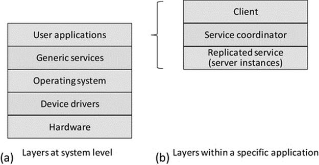
FIGURE 5.1 Generalization of the use of layers to provide structure.
Figure 5.1 illustrates in a generalized way how systems can be organized into layers to provide structure and thus manage complexity. Modern systems are too complex for users to be able to understand in their entirety, and therefore, it is difficult and cumbersome to make configuration choices across the full range of functionality in order to use the system. Separation into layers limits the scope of each layer and allows relevant configuration to occur while abstracting away details that are the concern of other layers. Part (a) of the figure shows how layers can be used to separate the concerns of applications from those of systems software and hardware. To put this into context, when using a particular application, the user should only have to interface with the application itself. It is undesirable from a usability viewpoint for the user to have to configure support services or make adjustments to operating settings in order to use the application. A simple example of this in practice is the use of a word processing application to write this paragraph. The application is one of many on my computer that can use the keyboard. The application indicates to the operating system that it requires input from the keyboard and the operating system performs the input stream mapping from the keyboard device driver to the word processing process without the user having to get involved or even being aware of this taking place. The operating system automatically maps the keyboard device to other processes if the user switches between different applications (e.g., once I get to the end of this paragraph, I might check my e-mail before continuing with the book). There is also the issue of hardware updates; if I replace my keyboard with a different one (perhaps one with additional function keys or an integrated roller ball), it is likely that a new device driver will be needed for the new keyboard. I do not want to have to reconfigure my word processing application to accommodate the new keyboard; the operating system should remap the input stream of my application process to the new device driver in a way that is transparent to the process itself and thus to the user.
Part (b) of the figure illustrates how applications can themselves be internally structured into several layers (this ability to subdivide also applies to the other parts of the system shown in part (a)). An important example is shown in which an application is divided into several components, of which the user is only exposed to the client part (hence, it is shown as the topmost component; conceptually, the user is looking down from above). This theme is explored in detail in Section 5.5 of this chapter.
The beneficial use of layers in network protocol stacks has been discussed in Chapter 3 and provides further justification of the value of layered structures to ensure maintainability and manageability of complex systems with rich functionality.
Layered architectures are very popular for distributed systems. The reasons for this include the following:
• Within a distributed system, there may be many distributed applications. These applications may each share some services; a good example of this is an authentication service that thus ensures that specific users have consistent access rights to services across the entire system and thus the security of the system is less likely to suffer weaknesses that would arise if some points of entry are less well protected than others. It can be useful to logically separate out the distributed end applications (the ones that provide service to users), from the service applications (which may themselves be distributed but provide services to other applications rather than directly to users). Figure 5.2 illustrates the situation where multiple end applications interact with multiple services; the use of layers maintains structure.
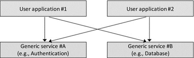
FIGURE 5.2 Layers facilitate logical separation of types of components and provide structure for interaction between components of systems.
• In addition to distributed applications and services, there is the system software that includes operating systems and various specialized components such as device drivers. The system software itself can be very complex in terms of the number of components it comprises and the range of functionalities it provides.
• The layers provide a structure, in which components occupy the same layer as similar components; sit in higher layers than the components they control or coordinate or use the services of; and sit below components that coordinate them or that they provide service to.
• There is a natural coupling between adjacent layers. There is also a decoupling of nonadjacent layers that contributes to flexibility and adaptability; this encourages clear division of roles and functionality between categories of components and also encourages the use of standardized and well-documented interfaces between components (especially at the boundaries between layers).
5.2.5 Hierarchical Architectures
A hierarchical architecture comprises multiple levels of components connected in such a way as to reflect the control and communication relationships between them. The higher node in a particular relationship is referred to as the parent, while the lower node in the relationship is referred to as the child. A node that has no nodes below it is termed a leaf node. Hierarchal organization has the potential to achieve scalability, control, configuration, and structure simultaneously.
The hierarchy illustrates the relative significance of the components, those being higher in the structure typically having more central or key roles. This maps onto the way most businesses are organized, with senior central managers higher in the structure, then department leaders, while workers with very specific well-defined areas of responsibility (functionality) occupying the leaf nodes. In hierarchically organized businesses, the normal communication is between workers and their manager (who is at the next level up in the structure). If something has to be passed up to a higher level, it is normally relayed via the managers at each level and not passed directly between nonadjacent layers. This has the effect of maintaining a clear control and communication regime that is appropriate for many large organizations that would otherwise struggle with scalability issues (e.g., imagine the complexity and confusion that could result if all workers in a large company contacted the senior management on a daily basis). Another example of the use of hierarchy is in the organization of large groups of people, such as armies, police forces, and governments. In such cases, it is important to have central decision making for the highest-level strategies, while more localized decisions are made lower in the structure. The result is hopefully a balance between a uniform centrally managed system with respect to major policy while allowing local autonomy for issues that do not need the attention of the senior leadership.
However, rigid hierarchical structures can work against flexibility and dynamism; for example, the need to pass messages up through several layers causes overheads and delays. Reorganizations can be prohibitively complex especially where components are heavily interconnected.
Figure 5.3 illustrates common variations of hierarchical structures. Broad (or flat) trees are characterized by having few levels and a large number of components connected at the same level to a single parent node; this can affect scalability because the parent node must manage and communicate with each of the child nodes. Deep trees have many layers with relatively few nodes at each layer. This can be useful where such a detailed functional separation is justified, but in general, the additional layers are problematic because they add complexity. The main specific problems are increases in the communication costs and the latency of communication and control, as on average messages have to be passed up and down more levels of the tree. In general, a balanced tree (i.e., a balance is achieved between the breadth and the depth of the tree) is close to optimal in terms of the compromise between short average path lengths for communication and also the need to limit the number of subordinates at any point in the tree for manageability. A binary tree is a special case in which each node has (at most) two subordinates. These are more likely to be found within data structures than in system component architectures but are included here for completeness.
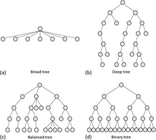
FIGURE 5.3 Hierarchical structures.
5.3 Heterogeneity
Homogeneous systems are those in which all computers are the same, in terms of their hardware and configuration, resources, and operating system. These systems exist when, for example, a company or university equips an office or a laboratory with identical computers or a bespoke sensor system with identical sensor nodes is deployed. However, in the general case, processing systems are not identical and the various differences between them can impact on the configuration and management effort and can cause problems for interoperability, of varying complexity.
Heterogeneity is a very important concept for distributed systems, both in terms of a purposeful architectural feature to achieve a certain performance or behavior and in terms of it being one of the main challenges for interoperability and code portability.
5.3.1 Definitions and Sources of Heterogeneity
There are three main causes of heterogeneity, these being technological, intended, and accidental. Technological advances lead to new platforms or better resourced upgrades of earlier platforms. Other technological factors include advances in operating systems and programming languages as well as the occasional introduction of new network protocols. Heterogeneity is often intentionally introduced through design or configuration. For example, when more powerful platforms are used to host services, while users have less powerful workstations to access the services. A second example is where an operating system such as Microsoft Windows is chosen for the access workstation because of the popular user interface it provides, while Unix is chosen for the service-hosting platforms due to it having better configurability. A third example is where a service is hosted on a conventional static computer, while mobile computing devices, with completely different platforms and resource levels, are used to access the service. Heterogeneity is accidentally introduced, for example, when there are staged upgrades across hardware systems or when individual machines are enhanced or when different versions of the same base operating system are installed on different computers. Even an automated online update of the operating system that occurs on one computer but not on another potentially introduces heterogeneity if the behavior of one is changed in a way that the behavior of the other is not.
There are three main categories of heterogeneity: performance, platform, and operating system.
Performance heterogeneity arises from differences in resource provision leading to different performance of computing units. Common resource characteristics that lead to performance heterogeneity include memory size, memory access speed, disk size, disk access speed, processor speed, and network bandwidth at the computer-to-access network interface. In general, it is unlikely that any two computers will have identical resource configuration, and thus, there will usually be some element of different performances. There are many ways in which performance heterogeneity arises through normal system acquisition, upgrade, and configuration of hosted services such as file systems. Even buying computers in two batches a few months apart can lead to differences in the actual processor speed, memory size, or disk size supplied.
Platform heterogeneity (also termed architecture heterogeneity) arises from differences in the underlying platform, hardware facilities, instruction set, storage and transmission byte ordering, the number of actual processors within each machine's core, etc.
Operating system heterogeneity arises from differences that occur between different operating systems or different versions of operating systems. These include differences in the process interface, different types of thread provision, different levels of security, different services offered, and the extent to which interfaces are standard or open (published) versus proprietary designs. These differences affect the compatibility of, and challenges involved with porting of, software between the systems.
5.3.2 Performance Heterogeneity
Figure 5.4 shows three computers, all having the same hardware platform and operating system. Computers A and B have the same level of resource and are thus performance homogeneous. Computer C has different levels of resource, having a slower CPU processing speed, more primary memory, and a smaller hard disk. All three computers will run the same applications, with the same operating system interface and support and the same executable files (as the hardware instruction set is the same in all cases). However, applications will perform differently on computer C than on A or B. Applications requiring a lot of file storage space are more likely to exceed capacity on computer C, and compute-intense applications will take longer to run. However, applications requiring a lot of primary memory may perform better on computer C. This is a simplified example that only considers the main resource types.
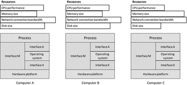
FIGURE 5.4 Performance heterogeneity.
The example illustrated in Figure 5.4 represents the very common scenario that arises from piecemeal upgrade and replacement of systems, resulting in situations where you have a pair of computers configured with the same CPU and operating system, but, for example, one has had a memory expansion or been fitted with a larger or faster access time hard disk.
5.3.3 Platform Heterogeneity
Figure 5.5 illustrates a platform heterogeneous system. Each of the three computers D, E, and F has a different hardware platform, but all three run compatible variants of the same operating system.
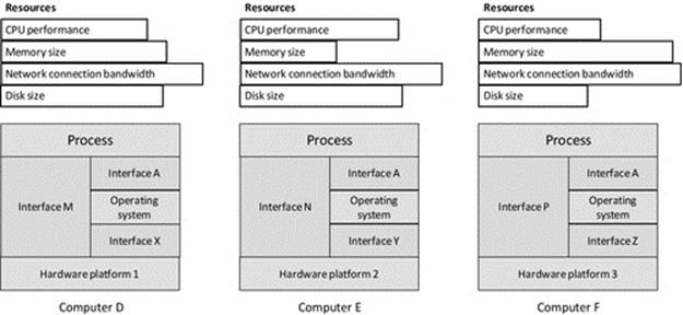
FIGURE 5.5 Platform heterogeneity.
Different platforms imply that the computers have different types of processor architecture, although different versions of the same processor family also represent a form of platform heterogeneity in cases where the run-time interface is different and thus the application code must be recompiled to run (e.g., one version of the processor family may support additional hardware instructions not available in the others). To some extent, performance heterogeneity (as a side effect) is inevitable in such cases because the CPUs may operate at different processing speeds (the number of instructions executed per second) or have different levels of internal optimization (such as branch prediction techniques to allow additional machine code instructions to be prefetched into cache ahead of execution). The interface between the platform and the operating system is different in each case; note the different interfaces X, Y, and Z, which means that different versions of the operating system are needed for each platform. If the operating system is the same, as in the three scenarios shown, the process interface to the operating system will remain the same; that is, it will have the same system calls to interface with devices, files, programmable timers, threads, the network, etc. Linux provides a very good example of this scenario in which the same operating system runs on many different platforms but provides the same process interface in each case. However, even though the source code for the applications could be the same in the three scenarios shown in Figure 5.5, the code will have to be compiled specifically for each platform, as the process-to-machine interface is different in each case (see interfaces M, N, and P). The differences, at this “machine code” level, may include a different instruction set, a different register set, and a different memory map.
5.3.4 Operating System Heterogeneity
Figure 5.6 illustrates operating system heterogeneity. In the scenario shown, all three computers G, H, and J have different operating systems but the same hardware platform. The three different operating systems will each have to use the facilities of the same platform type, so there will be differences in the interface between the operating system and the hardware, that is, interfaces X, Y, and Z, although the differences are in the ways the different operating systems use the resources of the hardware, rather than the interface provided by the hardware per se (which is actually constant in the three configurations shown). Although the application process has the same business-level behavior in all three systems, the way this is achieved at the code level will differ slightly as the different operating systems will have different interfaces (fundamentally the set of system calls and the syntax and semantics of their use). For example, there may be different versions of the file handling commands available, with differences in the parameters passed to them. This is reflected in the figure by the different process-to-operating system interfaces A, B, and C. Transferring applications from one of these computers to another is called porting and would require modification of those parts of the code that are sensitive to the differences in the operating system calls supported. As the hardware platforms are the same in each case, the same machine code interface is provided in each case. Changing the operating system may affect the effective resource provision of the computer and so impacts on performance. The most notable way in which this tends to occur is in terms of the amount of memory taken up by the operating system and thus the amount of memory remaining for user processes to use. This is reflected in the figure by the different amount of memory resource shown for each computer (i.e., it is based on the effective resource availability after the operating system has taken its share of the resource).
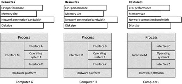
FIGURE 5.6 Operating system heterogeneity.
5.3.5 Impact of Heterogeneity
All forms of heterogeneity potentially impact on interoperability. Applications that operate in platform heterogeneous or operating systems heterogeneous systems thus rely on standardized communications between the platforms. This requires standard interfaces and protocols to ensure that the contents of messages and the semantics of communication itself are preserved when a message is passed between two dissimilar computer systems. The sockets API that operates at the transport layer and has been discussed in detail in the communication view chapter provides a good example of a standard interface at the process level. The sockets API is supported by almost all operating systems and programming languages and across almost all platforms.
The TCP and UDP protocols (of the TCP/IP protocol suite) are very good examples of standard protocols that facilitate interoperability between almost any combinations of platforms, using the sockets interface to a process as the end point for communication. These two protocols are extremely important for the Internet; they are not only used directly to provide bespoke process-to-process communication (as, e.g., in the case study game) but also used to construct most of the higher-layer communication mechanisms such as RPC, RMI, middleware, and web services.
These protocols are examples of the few invariants in distributed systems that have stood the test of time. The extent that they are embedded into such a wide range of essential services and higher-layer communication mechanisms reinforces their value as standards. It is relatively safe to assume that support for these protocols will remain for many years to come: future-proofing communications based on these protocols.
Performance heterogeneity is very common, to the extent that it is sometimes difficult to find computers with identical performance. However, if this is the only type of heterogeneity present, then applications will generally operate correctly on any of the host computers; but the overall speed and responsiveness will vary depending on the actual resource provision. Ideally, the functional split across software components and the subsequent deployment of these components onto processing nodes should match resource provision to ensure that the intended performance is achieved (but this is subject to the limitations of the design-time knowledge of the eventual run-time systems).
Platform heterogeneity is increasingly common, especially with the recent explosion of popularity of mobile devices including smart phones and tablets. Users demand applications that operate the same on their personal computer (PC), their phone, and their tablet, fundamentally because there is a desire to be “always connected” to favorite applications whether at home, in the office, or traveling between. It is not always possible to make applications identical on the different platforms, for example, the user interface on a smartphone with a touch screen cannot be identical to the user interface on a PC using a keyboard and mouse. The different platforms have different levels of resource, and this is sometimes evident in the way the software responds, for example, a fast-action game running on a smartphone with a small screen cannot in general be as impressive and responsive as the same game running on a PC that has been optimized for gaming with a very fast processor, expanded memory, and graphics accelerator processor.
Support for platform heterogeneity can add significant cost to software projects. Firstly, there will need to be a design approach that separates out the core functionality, which is device-independent, from the device or platform-specific functionality (typically mostly related to the user interface), which must be developed separately for each platform (see Section 5.13). The more platforms that are supported and the greater diversity between these, the greater the additional costs will be. Secondly, there are the additional testing costs. Each time the software is upgraded, it must be tested on all supported platforms; this in itself can be problematic in terms of the man power needed and the availability of a test facility in which the various platforms are all available. Some difficult to track down faults may occur on one platform only, requiring specific fixes that must then be tested to ensure they don't destabilize the product when on the other platforms. In some software projects, the testing team may be larger than the software development team.
Porting of code from one platform to another is less costly than ongoing maintenance and support for code across multiple platforms simultaneously, although it can still be challenging and potentially very expensive. In the simplest case where the operating system on each target platform is the same and the platforms themselves are similar, porting may only require that the source code (unchanged) must be recompiled to run on the new platform. However, if the operating system is also different, or where the platforms have significant differences, porting can require partial redesign.
Operating system heterogeneity introduces two main types of differences that affect processes: the first type being at the process-to-operating system interface and the second type being differences in the internal design and behavior of the operating systems. For the former, redesign of the sections of application code that make system calls (such as exec, read, write, and exit) and subsequent recompilation of the code may be sufficient. If the implementation of system calls is similar in the two operating systems, there may be no noticeable change in the application's behavior. However, for the latter, there potential problems in that the two operating systems may have different levels of robustness or one may have security weaknesses that the other may not have. For example, one operating system may be vulnerable to certain viruses and other threats that the other is immune to. There could also be effects on performance of applications due to differences in operating system behaviors including scheduling and resource allocation.
5.3.6 Porting of Software
Porting applications from one system to another can be very complex because the two host systems can be very different in the various ways discussed above. The end result may be applications that are functionally similar, but some aspects such as the user interface or the response time may be noticeably different due to resource availability. Browsers provide a good example where essentially, the same functionality is available but with different look and feel on the various different platforms they run on. Browser technology was initially established on the general-purpose PCs (laptop and desktop computers) for many years but has now been adapted to operate in the same well-understood ways on mobile devices, which have different processors and operating systems and generally fewer resources in terms of memory, processing speed, smaller displays, and often lower bandwidth network connections than their PC counterparts.
A virtual machine (VM) is a software program that sits between application processes and the underlying computer. As far as the computer's scheduler is concerned, the VM is the running process. The VM actually provides a run-time environment for applications that emulates the real underlying computer; we can say that the applications run in, or on, the VM. Because the application processes interact with the VM instead of the physical computer, the VM can mask the true nature of the physical computer and can enable programs compiled on different platforms to run. By providing a mock-up of the environment the application needs to run on, the VM approach avoids the need for porting per se. The VM approach is key to the way in which Java programs are executed. An application is compiled to a special format called Java bytecode; this is an intermediate format that is computer platform-neutral. A Java-specific VM (JVM) interprets the bytecode (i.e., it runs the instructions from the bytecode) the same regardless of the physical environment; therefore, portability is much less of an issue for Java programs generally than it is for programs written in other languages. The VM (or JVM) approach does of course require that a VM (or JVM) is available for each of the platforms that you wish to run the applications on. The VMs (or JVMs) themselves are platform-specific; they are compiled and run as a regular, native, process on whichever platform they are designed for. VMs and the JVM are discussed in more detail later in this chapter.
Middleware provides various services to applications that decouple some aspects of their operation from the underlying physical machine, especially with respect to access to resources that may be either local (on the same computer) or remote. In this way, middleware enables processes to execute in the same logical way regardless of their physical location. For example, the middleware may automatically locate resources the process needs or may automatically pass messages from one process to another without them having to have a direct connection or to even know the location of each other (refer to Section 5.5.1 in this chapter). The middleware may be implemented across different hardware platforms so that a process running on one platform type may transparently use resources located at a computer with a different platform type. Middleware does not however actually execute applications' instructions in the way that a VM does, and thus, it does not solve the portability problem directly. However, because middleware can enable the remote use of resources that are on different platforms, as well as communication between processes on different types of platforms, it offers an indirect solution to portability, that of transparent remote access, without the process actually moving to the other platform. An overview of middleware is provided later in this chapter and a more detailed discussion is provided in Chapter 6.
5.4 Hardware and System-Level Architectures
Distributed applications comprise software components that are dispersed across the various computers in the system. In order for these components to operate as a coherent single application, as opposed to isolated components doing their own thing, there need to be some means for the components to communicate. For this to be possible, there must be some form of connection between the underlying processors, on which the communication support software runs.
There are two fundamentally different approaches to connecting the processors together. Tightly coupled architectures are those in which the processors are part of a single physical system, and thus, the communication can be implemented by direct dedicated connections. In such systems, the processors may be equipped with special communication interfaces (or channels) designed for direct interconnection to other processors, without the need for a computer network. The processors share the resources of the computer, including the clock, memory, and IO devices.
Stand-alone computer architectures are those in which each processor is the core of a complete computer with its own dedicated set of resources. The PC, smartphone, tablet, and laptop computers are all examples of this class of computer. Stand-alone devices need an external network to communicate. There needs to be a network interface connecting each computer to the network as well as special communication software on each computer to send and receive messages over the network. This form of connecting the computers together yields a less tight and more flexible coupling; hence, it is termed loose coupling.
5.4.1 Tightly Coupled (Hardware) Systems
The main characteristic of tightly coupled systems is that they comprise a number of processor units integrated together in the same physical computer. This means that several threads of program code can run at the same time, that is, in parallel, since each processor can execute one instruction in each timestep. In these architectures, the communication channels between processor units are very short and can be implemented using similar technology to that of the processor units, meaning that communication can take place at similar speeds to memory accesses. In fact, since the processors usually have shared access to at least part of the system memory, it is possible for the program threads to actually communicate using the memory. For example, if one process writes a new value to a particular variable stored in a shared memory location, all of the other processes can read the variable, without the need to specifically send a message to each process. The main advantages of this form of communication are that it has the same near-perfect reliability as memory accesses and that it does not become a bottleneck in terms of performance; writing to memory is effectively the same operation as sending a data value to another processor. This means that parallel applications can be developed to solve algorithms in which there is high communication intensity (a high rate of communication between the processors). In contrast, such applications do not perform so well on loosely coupled architectures due to the presence of an external network technology that operates at lower speeds than memory accesses, has higher latency due to greater physical distances, and is also less reliable. In tightly coupled architectures, there is usually a single shared clock, and thus, it is possible to synchronize processes accurately in terms of the application-level events and resulting actions carried out. Each processor executes instructions at exactly the same rate; there can be no relative clock drift when there is only a single clock.
5.4.2 Loosely Coupled (Hardware) Systems
This book focuses on distributed applications that run on loosely coupled systems. These systems consist of a number of self-contained computers able to function independently of any others. A perfect example of this is the PC I'm using to write the book. The computer has its own power supply, processor, clock, memory, hard disk storage, operating system, and IO devices. However, the fact that the computer is self-contained does not necessarily mean that the computer can do what I require of it in isolation. Most of the applications that are used in modern business, as well as in hobbies and entertainment and social media, require access to data held at other computers and also require a means to communicate with other users, via the computers that they are using. Therefore, almost every computer has a network connection to support the communication requirements of distributed applications and data. This form of coupling is termed “loose” because the network is external to the computer itself. The communication over networks is slower and less reliable than in tightly coupled systems. However, the communication in loosely coupled systems can be flexibly reconfigured so that a particular computer can be logically connected to any other that is reachable in the network.
Each computer has its own set of resources, which is beneficial in general, because the local scheduler has control of the way the resources (such as memory and the processor's computing cycles) are shared across the local processes. However, the fact that each computer also has its own clock that governs the precise rate at which instructions are executed and is also used to keep track of wall clock time (the actual real-world notion of time) introduces some challenges of synchronization when running distributed applications. For example, it is difficult to determine the global sequence with which a particular set of detected events occur (such as stock-trading transactions or deposits and withdrawals on a particular bank account) or to ensure the correct sequence of a set of critical actions is maintained (such as opening and closing control valves in an automated chemical production factory) if the actual processes associated with the events and actions are executing on different computers with imperfectly synchronized clocks. The challenges of clock synchronization and some techniques to overcome these challenges are discussed in Chapter 6.
A further challenge arising for the use of interconnected but self-contained computers is that they can fail independently. Failures that occur when applications are quiescent do not corrupt data and thus are relatively easy to deal with. However, consider the failure of a computer during a data transfer. Whether or not the data become corrupted depends on a number of factors that include the exact timing with which the failure occurs and the extent to which the communication mechanism in use was designed to be robust with regard to maintaining data integrity.
Figure 5.7 illustrates the main concepts of tightly and loosely coupled hardware architectures. There are actually many variations of tightly coupled architectures—the main differences concerning access to memory and the way in which the processors communicate. In some designs, all of the memory is shared, while in others, there is also some private cache per processor (as shown), and some designs have dedicated communication channels between the processors.
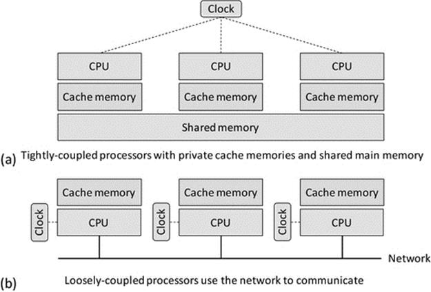
FIGURE 5.7 Tightly and loosely coupled hardware architectures.
5.4.3 Parallel Processing
Parallel processing is a special class of distributed application, which is briefly described here for completeness.
A parallel application generally comprises a number of processes all doing the same calculations but with different data and on different processors such that the total amount of computing performed per unit time is significantly higher than if only a single processor is used.
The amount of communication that occurs between the processes is highly dependent on the nature of the application itself. In most parallel applications, the data at each processing node are not processed in isolation; there is generally a need to interact with the computation of data values in other nodes, representing bordering regions of the application data space.
A classic example of a parallel processing application that most of us benefit from daily is weather forecasting, which uses specialized techniques such as computational fluid dynamics (CFD). The geographic area to be studied is divided up into small regions, which are further subdivided into smaller and smaller cells. The actual forecast of the weather at a particular time in the future, in a particular cell, is based not only on the history of weather conditions in the cell at times leading up to the forecast time but also on the weather conditions in the neighboring cells at each of those times, which influences the weather in our cell of interest. The weather conditions in the direct neighbor cells of our cell of interest are also affected by the conditions in the neighbors of neighbors cells at each timestep, and so it goes on. CFD works in iterations such that the state of each of the cells at a particular time point t1 is computed based on the state of the cell at time t0 and also the state of the neighboring cells at time t0. Once the new state of the cells at time t1 is computed, it becomes the starting point for the next iteration to compute the state of the cells at time t2. The total amount of computation is determined by the complexity of the actual algorithm and the number of cells in the model and the number of timesteps (e.g., the actual weather forecast for a region the size of the United Kingdom may work with a geographic data cell size of perhaps 1.5 km2). The amount of communication depends on the extent of the dependency between the cells during the iteration steps of the algorithm.
A parallel application that has a high ratio of computation to communication (i.e., it does a lot of computation in between each communication episode) may be suited to operation on loosely coupled systems. However, an application where the communication occurs at a high rate with a low amount of computation in between the communication is only suitable for execution on specialized tightly coupled architectures. If executed on a loosely coupled system, such applications tend to progress slower, possibly even slower than an equivalent nonparallel version on a single processor. This is because of the communication latency and that the total communication requirement can exceed the communication bandwidth available, so more time is spent waiting for the communication medium to become free and for messages to be transmitted than actually performing useful processing.
5.5 Software Architectures
In distributed applications, the business logic is split across two or more components. A good design will ensure that this is done to achieve a “separation of concerns” to the greatest extent possible. By this, it is meant that it is ideal to split the logical boundary of components on a functional basis rather than on a more abstract basis. If the logic is divided into components on an arbitrary basis (e.g., perhaps to try to keep all components the same size), then there will likely be more communication and interdependence between the resulting components. This can lead to a more complex and fragile structure because problems affecting one component also affect directly coupled components and can be propagated through a chain of components.
A design in which component boundaries are aligned with the natural functional behavior boundaries can result in a much less coupled structure in which individual functionalities can be replaced or upgraded without destabilizing the entire architecture, and whereby faults can be contained, such that a failed component does not lead to a domino-effect collapse. Dividing the business logic along functional lines also makes it possible to target robustness and recovery mechanisms (such as replication of services) to specific areas of the system that either are more critical to system operation or perhaps are more sensitive to external events and thus more likely to fail.
The way in which the business logic is functionally divided across the components is in many cases the single most significant factor that influences the performance, robustness, and efficiency of distributed applications. This is because it affects the way in which binding between components takes place and the extent of, and complexity of, communication. If done badly, the intensity of communication may be several times higher than the optimal level.
Some functionality however needs to be implemented across several components, due to the way the application is structured or operates. For example, the business logic of a client-server (CS) application may distribute the management and storage of state information across the two types of component. State that is needed only on the client side may be managed within the client component (improving scalability because the server's workload per client is reduced), while shared state needs to be managed and stored at the server side because it is accessed by transactions involving several clients.
5.5.1 Coupling Between Software Components
There are a variety of ways in which multiple software components (running as processes) can be connected together in order to achieve a certain configuration or structure. The application-level business logic and behavior are thus defined by the collective logic of the components and communication between them. The term “coupling” is used to describe the ways in which the various processes are connected together in order to achieve the higher business-level (logical) connectivity. The nature of this coupling is a critical aspect of successful design of distributed systems.
As discussed above, excessive connections and direct dependencies between components are generally problematic in terms of scalability and robustness. Direct dependencies also inhibit dynamic reconfiguration, which is increasingly important in highly complex feature-rich applications and in application domains in which the operating environment is itself highly dynamic.
There are several forms of coupling as explained below. Whether the coupling is tight or loose is determined by the extent of run-time flexibility built in at design time.
Tight (or fixed) coupling is characterized by design time-decided connections between specific components. Explicit references to other components introduce direct dependencies between the components, which means that the application can only function if all of the required components (as per its fixed design-time architecture) are available. If one component fails, the other components that depend on it either fail or at least cannot provide the functionalities that the failed component contributes to. Thus, tightly coupled design tends to increase sensitivity to failure, reduce flexibility, reduce scalability, increase the difficultly of maintenance, and inhibit run-time reconfigurability.
Loosely coupled (decoupled) components do not have connections with specific other components decided at design time. This form of coupling is characterized by intermediary services, which provide communication between components (such as middleware), and/or by the use of dynamic component discovery mechanisms (such as service advertisement). The components are coupled with indirect references. This is a run-time flexible approach as it is possible for the intermediary service to modify the references to other components based on the at-the-time availability of other components; thus, components are not directly dependent on specific instances of other components or processes. For example, a client could be mapped to one of many instances of a service, depending on availability at the time the service request is made, thus making the application robust with respect to the failure of individual service components. Intercomponent mapping can also be based on a description of required functionality rather than based on a specific component ID, thus, at run time, the intermediary (such as middleware) can connect components based on a matching of what one needs and what the other provides.
As loose coupling uses external services or mechanisms to provide the mapping between pairs of components, it has the potential to make applications access and location transparent. Loosely coupled applications are easier to maintain as upgrades can be supported by changing the run-time mapping to swap the new version of a component into the position held by the old version. Loosely coupled applications are also extensible as new components with new functionality can be added without redesigning the other components or recompiling the system. See Figure 5.8.
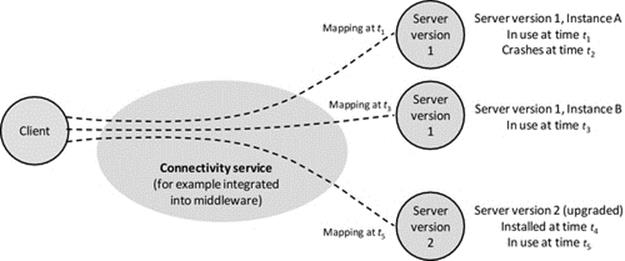
FIGURE 5.8 Dynamic mapping in loosely coupled systems.
Figure 5.8 illustrates the advantages of loose coupling. The dynamic mapping facilitates location transparency as the client does not need to know the location of the service component. This enables automatic remapping to a different service instance if the currently used one fails (as between times t1 and t3 when server instance A of the service fails and the client requests are remapped to instance B of the same service) and also remapping to an upgraded version of a service (as between times t3 and t5 when the service is upgraded and subsequent client requests are mapped to a new version 2 server instance). Access transparency is also provided in some cases where the connectivity service handles differences in the application service interfaces (arising, e.g., during a service upgrade) so that the client components remain unchanged. This is very important where there are high numbers of clients deployed and upgrading them all in step with each server upgrade would be expensive in terms of logistics, time, and effort and risks the situation where different versions of the client could be in use in the system at the same time.
Logical connections can be direct between communicating components or can be facilitated indirectly by intermediate components:
Direct coupling is characterized by the fact that the process-to-process-level connections correspond with the application's business-level communication. The transport layer logical connections map directly onto the higher-level connectivity. For example, there may be a direct TCP or UDP connection between the business-level components.
Indirect coupling describes the situation where components interact through an intermediary. A stock-trading system provides an example where clients have private connections but see the effects of other clients' trades (in the form of changes in the stock price), which may lead to further transactions. Another example is provided by a multiplayer game hosted on a central server, where the game clients are each aware of the other's presence at the application level (they are logically connected by the fact that they are opponents in the same game) but are not directly connected together as components. Each client is connected only to the server and any communication between the clients is passed to the server and forwarded to the other client. The use-case game application provides a useful example of this form of coupling. A further example is e-mail, in which people use their e-mail clients to send e-mail messages to each other (the logical connection is in terms of the e-mail conversation). The e-mail clients each connect to the users' respective e-mail server, which holds their mail inbox and also sends outgoing mail; see Figure 5.9.
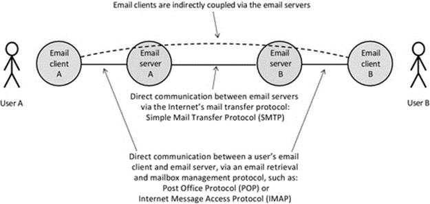
FIGURE 5.9 Sending e-mail involves several components. E-mail clients are indirectly coupled.
Figure 5.9 uses e-mail to illustrate indirect coupling. The users (actually the e-mail client processes they use) have a logical connection in the passing of e-mail messages at the application level. The e-mail clients are not connected directly, not even if both users have the same e-mail server. In the figure, there are two intermediaries between the e-mail clients. Each client is directly coupled to its respective e-mail server, and the two servers are directly coupled to each other. Notice that this does not affect whether the directly coupled components are tightly or loosely coupled; this depends on how the association between the components is made (e.g., there could be an intermediary service such as middleware that provides dynamic connectivity).
Isolated coupling describes the situation where components are not coupled together and do not communicate with each other although they are part of the same system. For example, a pair of clients each connected to the same server do not need to communicate directly or even be aware that the other exists. Consider, for example, two users of an online banking system. Their client processes each access the banking server, but there is no logical association between the two clients; they each have independent logical connections with the bank. The e-mail example shown in Figure 5.9 provides the framework for another example: consider two users who do not know each other and never send e-mails to each other. The respective e-mail client processes are each part of the same system but have no logical association in this case, and thus, the processes are not coupled together.
Figure 5.10 illustrates the coupling variations possible, based on a CS application as an example. Part (a) shows direct coupling in which the business-level connectivity is reflected directly by the process-to-process connection. This is a very common configuration in small-scale applications. Part (b) shows indirect coupling using a specific component as an intermediary that forwards communication between the connected processes. The central component is part of the application and participates in, and possibly manages, the business-level connectivity; this is reflected in the figure by the business logic connection being shown to pass through the server component. The use-case game provides an example of this, as the server needs to observe game-state changes, update its own representation of the game state, and forward the moves made by one client to the other. The server also has to check for game-end conditions, that is, one client has won or it was a draw and also needs to regulate the turn-based activity of the clients. Part (c) comprises parts (a) and (b) to illustrate tight coupling between components, that is, where the components connect directly to specific other components with which they have a business logic relationship. The application-level architecture is “designed into” these components such that they connect to other components in a predecided way. Part (d) shows that clients using a common service, where each client interaction with the service is private to that specific client, are isolated (i.e., the clients are not coupled to each another) at the business level. Each client obtains service from the server without interaction with, or knowledge of the presence of, the other clients. Part (e) shows how an external connectivity mechanism or service, such as middleware, can be used to provide connectivity between processes without them having to actually form or manage the connectivity directly between themselves. The connectivity mechanism is not part of the application and does not participate in the business-level connectivity; its role is to transparently pass messages between the two components without knowledge of their meaning or content. This is a much more flexible means of connecting processes and is very important for large-scale or dynamically reconfigurable applications. Each of the direct and indirect coupling modes can be achieved in loosely coupled ways, as confirmed by part (f) of the figure, where the messages are passed through the middleware instead of directly between components, but the component relationships at the business logic level are unchanged.
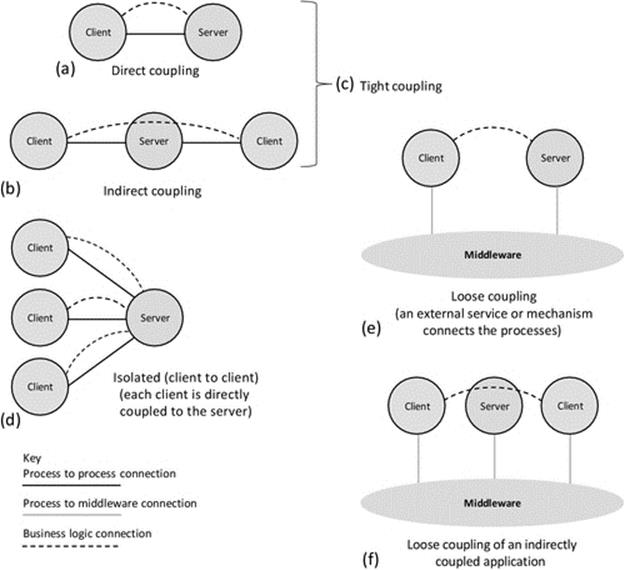
FIGURE 5.10 Coupling variations, illustrated in the context of a client-server application.
Scalability is in general inversely related to the extent of coupling between components due to the communication and synchronization overheads that coupling introduces. Therefore, excessive coupling can be seen as a cost and should be avoided by design where possible. Thus, for large systems, scalable design will tend to require that most of the components are isolated with respect to each other and that each component is only coupled with the minimum necessary set of other components.
Figure 5.11 shows two different possible couplings between components in the same system. Part (a) shows a tree configuration that tends to be efficient so long as the natural communication channels are not impeded by having to forward messages through several components. This requires good design so that the case where a message is passed from a leaf node up to the root of the tree and down a different branch to another leaf is a rare occurrence and that most communication occurs between pairs of components that are adjacent in the tree. Part (b) shows a significantly more complex mapping, which introduces a higher degree of intercomponent dependency. It may be that the complexity of the connectivity is inherent in the application logic and cannot be further simplified, although such a mapping should be carefully scrutinized.
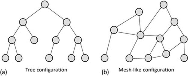
FIGURE 5.11 Different complexities of component coupling.
5.6 Taxonomy of Software Architecture Classes
The various activities performed by an application can be generically divided into three main strands of functionality: The first strand is related to the user interface, the second strand is the business logic of the application, and the third strand is functionality related to storage of and access to data. These are three areas of functionality that are usually present in all applications to some extent, and if their descriptions are kept general enough, they tend to cover all common activities. This broad categorization is very useful as a means of describing and comparing the distribution of functionalities over the various components of a system. Note that the description in terms of these strands is purposely kept at a high level and is thus more useful to describe and classify the approach taken in the distribution (i.e., in terms of the overall design and behavioral effect of the design) rather than to describe specific features of a design in any detail.
5.6.1 Single-Tier Applications
A single-tier application is one in which the three main strands of functionality are all combined within a single component, that is, there is no distribution. Such applications tend to be local utilities that have restricted functionality. In terms of business applications, single-tier design is becoming quite rare as it lacks the connectivity and data-sharing qualities necessary to achieve the more advanced behaviors needed in many applications.
Figure 5.12 illustrates the mapping of the three main strands of functionality onto a single application component. Such applications are sometimes referred to as stand-alone applications.
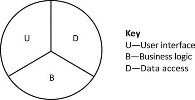
FIGURE 5.12 Single-tier design places all of the main strands of functionality in a single-component type.
5.6.2 Two-Tier Applications
Two-tier applications split the main strands of functionality across two types of component. The most common example of a two-tier application is the CS architecture (discussed in detail later).
Figure 5.13 shows some of the possible variations of functionality distribution for CS applications. Note that the figure is illustrative only and is not intended to provide an accurate indication as to the proportion of processing effort dedicated to each of the functional strands.
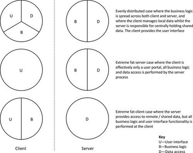
FIGURE 5.13 Two-tier design distributes the main strands of functionality across two-component types.
Peer-to-peer applications (also discussed later in detail) can be considered a hybrid between the single-tier and two-tier approaches. This is because each peer instance is essentially self-contained and thus has elements of all of the three functionality strands. However, to cooperate as peers, there must be some communication between instances, for example, it is common for peer-to-peer applications to facilitate data sharing, where each peer holds a subset of data and makes it available to other peers on demand (seeFigure 5.14).
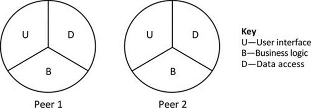
FIGURE 5.14 Peer-to-peer applications represented as a hybrid of single-tier and two-tier architecture.
As Figure 5.14 implies, each peer contains elements of each functional strand and therefore can operate independently to some extent. For example, a music-sharing peer can provide its locally held files to the local user without connection to any other peers. Once peers are connected, they can each share the data held by the others.
5.6.3 Three-Tier Applications
Three-tier applications split the main strands of functionality across three component types. A general aim of this architecture is to separate each main strand of functionality into its own tier; see Figure 5.15. The potential advantages of splitting into three tiers include performance and scalability (because the workload can be spread across different platforms and replication can be introduced at the middle tier and/or the data access tier as necessary) as well as improved maintainability and extensibility (because, if the interfaces between tiers are well designed, functionality can be added at one tier without having to reengineer the other tiers).
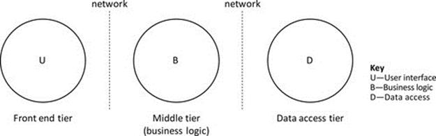
FIGURE 5.15 An idealized three-tier application.
Figure 5.15 illustrates an idealized three-tier application in which each of the three functional strands is implemented in a separate component to enhance scalability and performance. In reality, the separation of the functional strands is rarely this clean, and there will be some spread of the functional strands across the components. For example, there may be some data access logic and/or data storage in the middle tier, or there may be some aspect of business logic that is implemented in either the front-end or data access tiers because it may be more efficient or effective, depending on the actual application requirements.
5.6.4 Multitier Applications
Many applications have extensive functionality and require the use of various additional services beyond performing the underlying business role. For example, a banking application may need functionality associated with security and authentication (of users as well as connected systems), interest rates, currency exchange rates, funds transfers between in-house accounts and to/from externally held accounts, calculation of fees and charges, and many others, in addition to the basic operations of managing funds within a bank account. Such functionally diverse systems cannot be built effectively using two-tier or three-tier approaches. In order to manage the complexity of the system itself and to ensure its extensibility, as well as to ensure the maintainability of the subcomponents, these systems need potentially very many component types, and the distribution of functional strands across the components is highly dependent on the needs of each specific business system.
Figure 5.16 illustrates the concept of multitier design. The same basic ideas of three-tier design apply, but the functionality is spread over more component types to give a modular and thus more scalable and extensible design. A main motivation for this approach is to manage (limit) the complexity of each component type and to achieve flexibility in the way the components are used and connected. For example, there may be some specific functions that are not required in all installations of the software; if the mapping of functionality onto components is done appropriately, then the relevant components can be omitted from some deployments. The modular approach also facilitates upgrade of individual components without disrupting others.
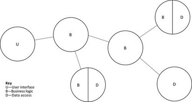
FIGURE 5.16 An example of functional distribution in a multitier application.
5.7 Client-Server
CS is perhaps the most well-known model of distributed computing. This is a two-tier model in which the three main strands of functionality are divided across two types of component.
A running instantiation of a CS application comprises at least two components: at least one client and at least one server. The application's business logic is divided across these components that have defined roles and interact in a prechoreographed way to various extents in different applications. The interaction is defined by the application-level protocol, so for a very simple example, the client may request a connection, send a request (for service) message, receive a reply from the server, and then close the connection. Application-level protocols are discussed in Chapter 3.
5.7.1 Lifetimes of Client and Server
In most CS applications, the server runs continually and the client connects when necessary. This arrangement reflects the typical underlying business need: that the server should be always available because it is not possible to know when human users will need service and hence run the client. Essentially, the user expects an on-demand service. However, the user has no control over the server, and clients cannot cause the server to be started on demand. The client is usually shutdown once the user session is ended.
It is not desirable to leave the client components running continuously for several reasons that include the following:
1. It would use resources while active even when no requests are made, and there is no certainty that any further requests will ever be made.
2. Keeping clients running requires that their host computers are also kept running, even when they are not actually needed by their owners.
3. Many business-related applications involve clients handling user-private or company-secret information and generally require some form of user authentication (examples include banking, e-commerce, and e-mail applications); so even if the client component itself remains running, the user session has to be ended (and typically that also ends the connection with the server). A new user would have to be authenticated and a new connection established with the server, hence still incurring a large fraction of the total latency incurred when restarting the component from scratch.
5.7.2 Active and Passive Sides of the Connection
The component that initiates a connection is described as the active side, and the component that waits for connection requests is described as the passive side. (Think of actively striking up a conversation with someone, as opposed to being approached by someone else who starts up a conversation with you. You don't have to do anything initially except to be there; hence, your behavior is passive.)
Client on-demand connection to services is supported by two main features of the way servers usually operate: firstly, the fact that servers tend to be continually available (as discussed above) and, secondly, because they tend to be bound to well-known ports and can be addressed by fixed URLs (i.e., they can be located using a service such as DNS; see the detailed discussion in Chapter 6).
5.7.3 The CS Architectural Model
CS is a logical architecture; it does not specify the relative physical locations of components, so they can be both on the same computer and on different computers. Each component runs as a process; therefore, the communication between them is at the transport layer (and above) and can be based on the use of sockets, the TCP or UDP protocols, and higher-level communication.
Figure 5.17 illustrates the general CS architecture, in a situation where two client processes are each connected to a single server. It is quite common that a server will allow many clients to be connected at one time, depending on the nature of the application, but the communication is private between the server and each client.
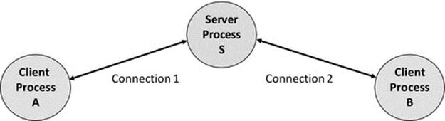
FIGURE 5.17 Client-server generalized representation.
CS is so named because normally, the server provides some sort of service to the clients. The communication is usually initiated by the client as the server cannot predict when a client will require service. Clients typically do not interact with each other directly as part of the CS application, and any communication that does occur between them is via the server. In many applications, the individual clients are unaware of each other's presence; in fact, this is a key design requirement for a wide variety of applications such as online banking, stock-trading, and media-steaming services.
In such applications, the business model is based on a private client-to-server relationship, which operates a request reply protocol in which the server responds to the requests of the client. The fact that there may be many clients simultaneously connected to the server should be completely hidden from the clients themselves; this is the requirement of concurrency transparency at the higher architecture level. However, a performance effect of other clients could become felt if the workload on the server is high enough that the clients queue for service on a timescale noticeable to the users (this is highly application-dependent). Techniques to ensure services remain responsive as load and scale increases include replication of servers, which is discussed in depth in this chapter and is also discussed from a transparency perspective in Chapter 6.
The clients in such applications can be said to be isolated from each other with respect to coupling, and they are independent of each other in terms of their business logic and function. The clients are each coupled with the server, either loosely or tightly depending on the design of the application-level protocol and the way that components are mapped to each other.
In contrast, a CS multiplayer game is a good example of an application where clients are logically connected via the game (their business logic) and thus are necessarily aware of each other and do interact but indirectly via the server (i.e., the clients are indirectly coupled to each other as discussed previously). In such an application, it is likely that the server will manage shared resources such as the game state and will control game flow, especially in turn-based games. In this case, the architecture fits the fat-server variant of CS; see the next section.
For interactive applications, the client is usually associated with human users (it acts as their agent). For example, an e-mail client connects to a remote e-mail service. The client provides an interface through which the user can request e-mail messages to be retrieved from the server or can send messages to the server to be sent as e-mails to other users.
Figure 5.18 illustrates a typical e-mail configuration and usage scenario. By holding the e-mail inbox centrally at a well-known location (which is identified by the domain part of the user's e-mail address URL), a user can access their e-mail from anywhere that they have a network connection. The user can access the server using one of several e-mail client programs running on different devices. The user interface and data presentation may be different in each case, but the actual data will be the same. Recipients of e-mail will not be able to determine which device, or e-mail client, was used to create the e-mail as all e-mails are actually sent out by the e-mail server.
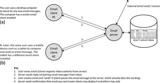
FIGURE 5.18 An e-mail application example of client-server configuration.
Application servers are often hosted on dedicated computers that are configured specially for the purpose (e.g., it might have larger memory and faster CPU to ensure it can handle requests at a high speed and with low delay). In such cases, the computer itself is sometimes referred to as being the server, but in fact, it is the process that is running on the computer, which is actually the server.
5.7.4 Variants of the CS Model
As discussed earlier, there are three main strands of functionality in distributed applications, related with the user interface, the business logic, and access to and maintenance of data, respectively. Several architectural variants of CS arise, based on different distributions of these functional strands over the client and server components.
As the names suggest, fat server (also known as thin client) describes a configuration in which most of the work is performed at the server, while in fat client (also known as thin server), most of the work is performed in the client. Balanced variants are those where the work is more evenly shared between the components (these variations were illustrated in Figure 5.13). Even within these broad categories, there are various ways the actual strands of functionality are distributed, for example, the client may hold some local state information, the remainder being managed at the server. In such a case, this should be designed such that the clients hold only the subset of state that is specific to individual clients and the server holds shared state.
Fat server configurations have advantages in terms of shared data accessibility (all the data access logic and data are held at a central location), security (business logic is concentrated on the server side and is thus protected from unauthorized modification, and all data accesses can be filtered based on authorization), and upgradeability (updates to the business logic only have to be applied to the small number of server components, and are thus potentially much simpler than when large numbers of deployed clients have to be upgraded).
Fat client configurations are appropriate when much of the data are local to the individual users and do not require sharing with other clients. Fat client design is also ideal in situations where the business logic is somehow customized for individual users (this could be relevant, e.g., in some games and business applications such as stock trading). An important advantage of the fat client approach is scalability. The client does much of the work, such that the server is by implication “thin” (does less work per client) and thus can support more clients as the incremental cost of adding clients is relatively low.
CS applications that distribute the business logic and the data access functions across both client and server components can be described as balanced configurations. In such applications, there are two categories of data: that which is used only by individual clients, such as personal data, historical usage data, preferences, and configuration settings and that which is shared across all or many of the clients and thus needs to be held centrally. The business logic may also be divided across the two-component types such that processing that is local to the client and does not require access to the shared data is performed on the client's host (e.g., to allow behavior customization or to add specialized options related to the preferences or needs of the particular client or the related user). This also has the benefit of reducing the burden on the server's host, making the service more responsive and improving scalability. However, the core business logic that manipulates shared data and/or is expected to be subject to future change runs at the server side for efficiency and to facilitate maintenance and updates. The balanced configuration represents a compromise between the flexibility advantages of the fat client approach and the advantages of centralized data storage and management (for security and consistency) of the fat server.
5.7.5 Stateful Versus Stateless Services
In some cases, the client may hold all the application state information, and the server holds none; it simply responds to each client request without keeping any details of the transaction history. This class of service is thus referred to as stateless; see Figure 5.19.
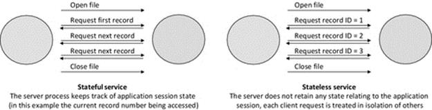
FIGURE 5.19 Stateful versus stateless services.
Figure 5.19 provides a comparison of stateful services, in which the server process keeps track of the state of the application, with stateless services, in which the server treats each new client request independently of all others and does not keep state information concerning the current application activity. The stateless approach is very powerful for achieving robustness, especially in high-scale systems. This is primarily because the failure of a stateful server disrupts the activities of all connected clients and requires the state be recovered to ensure ongoing consistency when the server is restarted, whereas the failure of a stateless server does not lose any state information. When a stateless server fails, its clients can be connected to a new instance of the server without the need for any state recovery (because each client maintains the state for its own application session, locally). Another way in which robustness is enhanced with the stateless server approach is that it leads to lower complexity in server components, making them easier to develop and test. The use-case multiplayer game provides an example of a stateful server design; the server stores the game state such as which player's turn it is to make a move.
5.7.6 Modular and Hierarchical CS Systems
Having only two-component types may be limiting in some situations. There may be a need to divide the functionality of a service across several subcomponents to ensure an effective design and to limit the complexity of any single component. Such distribution also tends to improve robustness, maintainability, and scalability. Consider the situation where a company has its own in-house authentication system, which is intended to validate all service requests in several different applications. There are three different CS applications used to provide the services necessary for the company's business, and each user has a single set of access credentials to use all three services.
One option would be to integrate the authentication system into each of the business services, so that when any client request arrives (at any of the servers), the same authentication activity would occur. This approach is undesirable because it requires that all three applications are reengineered and that the server components grow in terms of complexity, actual code size, and run-time resource requirement. The authentication logic has to be duplicated across the three services and this costs greater design, development, and testing effort. This approach also means that any future upgrade of the authentication system must be performed on all three copies; otherwise, there will be differences in behavior and the authentication strength may become inconsistent.
A better option from an architectural viewpoint would be to develop the authentication system as a separate service (let us assume that the CS model is appropriate for the purpose of the example). The server side of the authentication system will actually perform the authentication checks, which will involve comparing the credentials provided by clients against data held by the service to determine who has the rights to perform various actions or access data resources. The client side of the authentication service can be “thin” (see discussion above), such that it is suitable for integration into other services without adding much complexity. The authentication client can thus be built into the three business services the company uses, such that the authentication is consistent regardless of which business service is used and so that the authentication service can be maintained and upgraded independently of the business services.
To illustrate this hierarchical service scenario, a specific application example is presented: consider an application comprising two levels of service (database access and authentication service). The system is built with three types of component: the database server (which consists of the database itself and the business logic needed to access and update the data), the database client (which provides the user-local interface to access the database), and an authentication server (which holds information necessary to authenticate users of the database). Note that the database server needs to play the role of a client of the authentication service as it makes requests to have its users authenticated. This provides an example where a single component changes between client and server roles dynamically or plays both roles simultaneously,1 depending on the finer details of the behavioral design. This example is illustrated in Figure 5.20.

FIGURE 5.20 Modular services; the database service uses the authentication service.
Figure 5.20 illustrates a modular approach to services in which a database server makes service requests to a separate authentication service. Both of these services are implemented using the CS model, and the authentication client-side functionality is embedded into the database server component. In this way, the database server effectively becomes a client of the authentication service. This approach has further advantages in terms of transparency and security. The users do not need to access the authentication service directly; all accesses are performed indirectly via the other applications. This means that the user is not aware of the internal configuration and communications that occur. In part A of the figure, client A is authenticated to access the database, while in part B, client B is refused access; in both cases, it appears to the clients that the database server has performed the authentication check itself.
CS architectures can extend to situations in which a client needs access to more than one server, especially where an application component needs to access multiple remote or shared resources. An example of this is where the data required is spread across multiple databases or where a single database is itself distributed throughout a system. The scenario where a single component needs to access two separate databases is explored with the aid of Figure 5.21 in the next section.
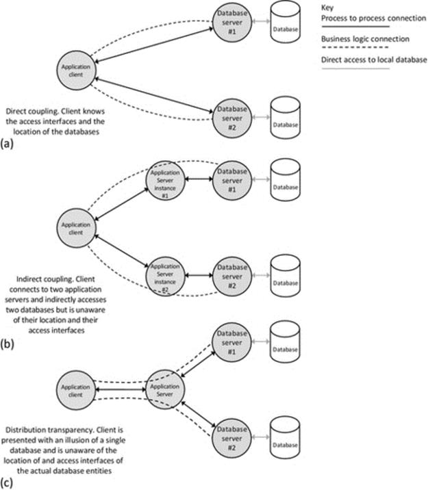
FIGURE 5.21 Two-tier direct coupling versus three-tier indirect coupling to services.
5.8 Three-Tier and Multitier Architectures
CS is a form of two-tier architecture, its main architectural strength being its simplicity. However, it is not particularly scalable for several reasons, which include (1) the application logic concentrated in the single server component type (and thus the complexity of the component increases approximately linearly with functionality); (2) the flexibility limitations and robustness limitations that arise from the direct communication relationships between the service user and the service provider; and (3) the performance bottleneck that arises because all clients connect to a specific service, which may comprise a single process instance.
The introduction of additional tiers, that is, splitting the application logic into smaller modules and distributing it over more types of component, provides greater flexibility and scalability and can also have other benefits such as robustness and security. These architectures have three or more tiers and are commonly referred to as three-tier architectures, but the term multitier is also used. Note that neither usage is strictly adhered to in terms of the actual number of tiers implemented.
The benefits of the three-tier architecture are illustrated using an example for which it is well suited: online banking. Consider some of the main design requirements for such an application:
• The service must be secure. There must be no unauthorized access to data.
• The service must be robust. There must be no data corruption and the system must remain consistent at all times. Individual component failures should not lead to overall system failure, and users should not be able to detect such component failures.
• The service must be highly scalable. There should be a straightforward way to expand capacity as the bank's customer base, or the set of services offered, grows.
• The service must be flexible. The bank needs to be able to change or add functionality. The operation of the system itself needs to comply with legislation such as data protection and privacy laws, which can be changed from time to time.
• The service must be highly available. Customers should be able to gain access to the service at any time of the day or night (the target is a 24/7/365 service).
Although these requirements have been stated specifically in the context of an online banking scenario, it turns out that they are actually generally representative of the requirements of a large proportion of corporate distributed applications. They are listed in a possible order of priority for a banking application, and this order will not necessarily be the same for other applications. In essence, the requirements are security, robustness, scalability, flexibility, and availability. Keeping the example quite high level, let us now consider the ways in which the three-tier architecture satisfies or contributes to each of these requirements.
Security. The client is decoupled from the data access tier by the middle business logic tier. This allows for robust user validation to occur before user requests are passed to the security-sensitive components. It also obscures the internal architecture of the system; an attacker may be able to send a fake request to the middle tier, but the system can be set up such that the third tier only accepts requests from the middle tier and that, when viewed externally from the bank's network, the third tier is not detectable.
Robustness. The three-tier architecture enables replication to be implemented at all tiers except the first tier. This is because each user must have exactly one client process to access the system; there can be many clients active at once, but this is not replication as each client is unique and is controlled independently by its user. The business logic tier and the data access tier can each be replicated, to different extents as necessary, to ensure that the service is robust. It is the design of the replication mechanism at the data access tier that contributes most significantly to ensuring data consistency despite individual component failures.
Scalability. Replication at both the business logic and the data access tiers also contributes to scalability. Additional instances of the components can be added to meet growing service demand. The second and third tiers can be scaled up asymmetrically depending on where the bottlenecks occur. For example, if user validation becomes a choke point as the load on the validation mechanisms is increased, then the business logic layer can be expanded with a higher replication factor than the data access layer, which may continue to perform satisfactorily with its current level of resource.
Flexibility. Recall that three-tier architectures are also sometimes called multitier. This is because there does not have to be exactly three layers and the use of terminology is not always precise. Consider what would happen if not only the user validation mechanism were to become a serious bottleneck due to increased load (as described in the paragraph above) but also the legislation governing the way that banks perform user validation was tightened up requiring significantly stronger checks are put in place (which are correspondingly more resource-intensive). In such a case, if the validation remains part of the business logic, this component type will become very complex and heavyweight. A better approach could be to introduce a new layer into the system and to separate out the user validation logic from the other business logic. The multitier approach allows for changes like this to occur in one layer without affecting the other components, so, for example, the user-client component and the data access component can ideally remain unchanged. This limits the cost of change and perhaps more significantly reduces the risks of instability that arise if too many things are changed at once.
Availability. Once again, it is the flexibility of being able to replicate at multiple layers that provides the basis for a highly available service. If some of the replicas are located at different physical sites, then the service can even continue to operate despite site-local disasters such as floods and power cuts. As long as at least one component of each type is operating, then it is possible that the overall service will be fully functional. Note however that this must be subject to meeting all other requirements; for example, the data consistency aspect of the robustness requirement may enforce that a minimum of, for example, three data access components are running at any time.
Three-tier architectures have further advantages over two-tier designs, the most important of these being the greater extent of transparency they provide and the additional benefits associated with this.
A generic database-oriented application that accesses two different databases is used to exemplify the transparency benefits arising through progression from a two-tier design to a three-tier design; this is explained with the aid of Figure 5.21.
Figure 5.21 illustrates the benefits of using additional tiers. The figure shows three possible ways to connect an application component to a pair of databases. Part (a) of the figure shows a two-tier configuration in which the component is connected directly to the database services. In this situation, all business logic is implemented in the single application component (which is shown as a client in the figure, because it makes service requests to the database service). This configuration is an example of direct coupling and has the advantage of low initial development cost and operational simplicity.
However, this configuration lacks transparency in several important ways. This configuration requires that the client-side application developer deals with the distribution of the components directly; we can say it is not distribution-transparent. The developer has to take account of which data are located at each database when developing the application code that accesses the data. Complex scenarios such as what should happen when only one of the databases is available, or if one fails to perform a transaction but the other succeeds (which can be especially complex in terms of data consistency), must be decided and the scenarios automatically detected and supported in the application logic.
In terms of location and access transparency, the client component must know or find the location of the database servers in order to connect and, because the connection is direct, must know the native format of the database interface. If the database type were changed, then the client component may have to be updated to account for changes in the interface to the databases, such as the message formats used, and the way in which logical connectivity with the database server is achieved (e.g., the way in which the client authenticates itself may change or be different for each of the two databases).
Part (b) of Figure 5.21 shows a more sophisticated alternative architecture in which a third tier is introduced. Part of the business logic is moved into application-level server components that handle the connectivity to and communication with the database services.
The application-level servers can perform additional functions such as security and access control, providing access and location transparency to the client: the former in the sense that the databases may have their own native formats, which the application server deals with, thus hiding these differences from the client, and the latter because the application server can deal with locating the database service without the client needing to know its location or having the required mechanism to locate it.
This approach is superior in several ways. Firstly, it hides the possible heterogeneity of the databases from the client making the client logic simpler. Secondly, it decouples the client component from the database components potentially improving security and robustness since authentication and filtering of requests can be added into the new tier if necessary, and thus, the client cannot directly manipulate the data. Thirdly, many clients can potentially use the same application server component. This centralizes the application business logic making the application generally easier to maintain and simplifying business logic upgrades.
Part (c) of Figure 5.21 shows a further developed architecture in which an application-level server deals with all aspects of database connectivity, such that the client is presented with the illusion that there is only a single database entity. This is achieved because the client only connects to a single application server, which takes care of the connection to the multiple databases, providing the client with a single-system abstraction. In this configuration, the server provides distribution transparency in addition to the other forms of transparency achieved by configuration (b).
Notice that configuration (c) is an example of a three-tier application: The application client is the first tier (the user interface), the application server is the second tier (the business logic), and the database server is the third tier (managing the data access). However, this arrangement of components could also be considered to be effectively two levels of CS in which the application logic is developed as a CS application, and the database is itself developed as a self-contained CS application and the two then merged together. In fact, this might be a helpful way to reason about the required functionality of the various components during the design phase. In the resulting three-tier architecture, the middle component (the application server) takes the role of client in one CS system and has the role of server in the other; see part (b) of Figure 5.22.
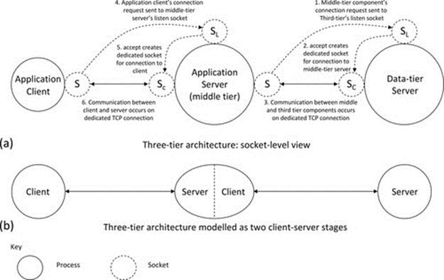
FIGURE 5.22 The three-tier architecture; some mechanistic aspects.
Figure 5.22 illustrates some mechanistic aspects of the three-tier architecture. Part (a) of the figure shows a possible communication configuration using sockets. In the configuration shown, the middle tier connects to the data tier (the data tier is the passive side and the middle tier is the active side that initiates the connection). The application client connects to the middle tier whenever service is needed (the application client is the active side and the middle tier is the passive side in this case). Part (b) of the figure shows a possible way to construct a three-tier architecture as two CS stages. This way of visualizing three-tier systems is particularly useful when considering the extension of existing two-tier applications or during the design phase of a three-tier application because it facilitates a modular approach to the design, and in particular, it can help with the elicitation of clear design requirements for the various components. The mechanistic detail shown in Figure 5.22 is applicable to both architectures (b) and (c) depicted in Figure 5.21.
The multiple database scenarios described above have been developed as a series of three application versions, which each map directly onto the configurations illustrated in Figure 5.21. Activity A1 explores the behavior of the three versions, to facilitate understanding of aspects such as the transparency differences between the configurations, the relative strengths and weaknesses of the different configurations, and the different coupling approaches represented.
The components in the three applications communicate over TCP connections, configured in the same manner as shown in part (a) of Figure 5.22.
There can be many reasons why data are distributed within a system. Data may be held in a variety of places based on, for example, the type of data or the ownership of the data or the security sensitivity of the data. It may be purposefully split across different servers to reduce the load on each server, thus improving performance. It may also be replicated, such that there are multiple copies of the same data available in the system. The distribution of data using different physical databases may also be a design preference to ensure maintainability and to manage complexity. For example, a retail company will very likely have an information structure that separates out the customer details into a customer database, the stock details into a stock database and the staff, and payroll details into a further database.
For any large system, the data are much more likely to be distributed than not. It would be generally undesirable for a large organization to collect all of its data about customers, suppliers, products, etc., into a single database, which would be complex and unwieldy, possibly require a very large amount of localized storage, and likely be a performance bottleneck because all data queries would be passed to the same server. In addition, many e-commerce applications operate across multiple organizations, and they are very unlikely to allow their data to be stored remotely, at the other organization's site. More likely, each organization will split their data into two categories: that that they are happy to allow remote organizations to access via a distributed e-commerce application and that that they wish to keep private.
The designers of distributed applications are thus faced with the challenge of accessing multiple databases (and other resources) from within a specific application such that the users of the system are unaware of the true locations of the data (or other resources) and do not have to be concerned with the complexity of the physical configuration of the underlying systems. This is a very useful
Activity A1
Exploring Two-Tier and Three-Tier Architectures
Three differently structured versions of the same application are used to explore a number of important aspects of software architectures.
The applications each access two different remote database servers. To simplify the configuration of the software and to ensure that the focus of the experimentation is on the architectural aspects (and not the installation and configuration of databases), the database server programs used in the activity actually hold their data in the form of in-memory data tables instead of real databases. This does not affect the architectural, communication, and connectivity aspects of their behavior.
Prerequisites
Copy the support materials required by this activity onto your computer; see Activity I1 in Chapter 1.
Learning Outcomes
To gain an understanding of different configurations of CS
To gain an appreciation of the distributed nature of resources in most systems
To understand robust design in which some services may be absent, but the remainder of the system still provides partial functionality
To understand the differences between two-tier and three-tier architectures
To gain an appreciation of different coupling approaches
To explore access transparency in a practical application setting
To explore location transparency in a practical application setting
To explore distribution transparency in a practical application setting
The activity is performed in three main stages.
Method Part A: Understanding the Concept of Distributed Data
The first part uses a two-tier implementation comprising the following software components: DB_Arch_DBServer_DB1_Direct (this is the implementation of the first of the two database servers and is used throughout the entire activity), DB_Arch_DBServer_DB2_Direct (this is the implementation of the second database server and is also used throughout the entire activity), and DB_Arch_AppClient (this version of the client connects directly to each of the two database servers). This configuration corresponds to part (a) of Figure 5.21.
The data needed by the client are split across the two database servers, such that each can provide a specific part of it independently of the other. One database server holds customer name details; the other holds customer account balance details. The single client thus needs to connect to both servers to retrieve all the relevant data for a particular customer but can retrieve partial data if only one of the servers is available.
This part of the activity demonstrates direct connection between the application client and the database servers. The location (address and port) of the database servers has to be known by the client. In the demonstration application, the port numbers have been hard-coded, and the server IP address of each server is assumed to be the same as that of the client; the user must enter the correct IP address if the server is located on a different computer.
The connectivity and behavior can be explored in three substeps.
Part A1. Run the client with a single database server.
Start by running the client (DB_Arch_AppClient) and the first of the two database servers (DB_Arch_DBServer_DB1_Direct) on the same computer. Attempt to connect the client to each server. This should succeed for the first database server and fail for the second. Since each connection is managed separately by the client in this particular design, the absence of one server does not interfere with the connectivity to the other.
Now request some data. Provide a customer ID number from the set supported {101, 102, 103} and click the “request data” button. You should see that the partial data held by the particular server that is running are retrieved. The application is designed to send the same request (i.e., the key is the customer ID) to all connected database servers, so the fact that one of the servers is unavailable does not prevent the other from returning its result, that is, only the customer name is returned to the client.
Part A2. Run the client with the other database server.
Confirm that that behavior is the symmetrical with regard to whichever of the databases is unavailable. This time, run the client (DB_Arch_AppClient) and the second of the two database servers (DB_Arch_DBServer_DB2_Direct) on the same computer. Follow the same steps as before. Once connected and a customer data request has been submitted, the database should return the appropriate customer account data, even though database #1 is not available to supply the customer name.
Part A3. Run the client with both database servers.
Now run the client and both database servers on the same computer. Connect the client to each database server, and then, submit a data request. Notice that the request in this case is sent to both database servers and that both respond with the data they hold, based on the customer ID key in the request message.
You may be able to just about notice the delay between the two data fields being updated in the client, which arises because the data arrive in two messages, from the two different database servers.
Expected Outcome for Part A
You should see that the distributed application functions correctly and that its behavior corresponds to what is expected based on the procedure described above.
You should see how the client sets up and manages the connections to the two databases separately.
Use the diagnostic event logs provided in the database server components to see details of the connections being established and messages being passed between the client and the servers. Make sure that you understand the behavior that occurs.
The screenshots below show the resulting behavior when all three components interact successfully, for part A3 of the activity.
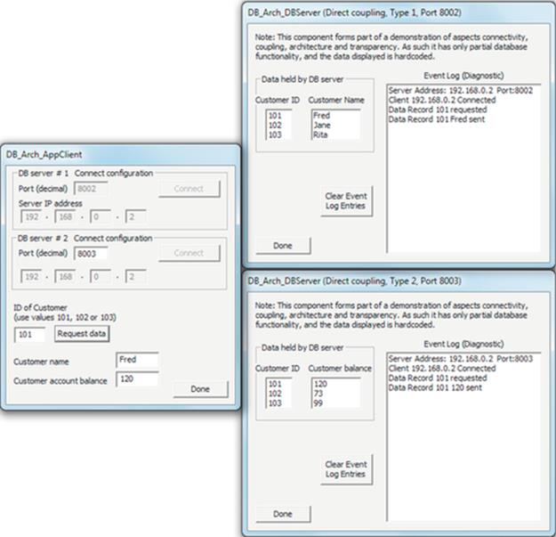
Method Part B: Extending to Three Tiers
This part of the activity is concerned with the introduction of a middle tier to decouple the application client from the database servers (which were directly connected to the client in the configuration used in part A).
This second part of the activity introduces a pair of application servers that each deal with the connection to one of the database servers. This configuration comprises the following five software components: DB_Arch_DBServer_DB1_Direct (the implementation of the first of the two database servers), DB_Arch_DBServer_DB2_Direct (the implementation of the second of the two database servers), DB_Arch_AppServer_for_DB1 (the middle tier that connects to the first database type), DB_Arch_AppServer_for_DB2 (the middle tier that connects to the second database type), and DB_Arch_AppClient_for_AppServer1and2 (a modified client component that connects to the new middle-tier application servers instead of directly connecting to the database servers). This configuration corresponds to part (b) of Figure 5.21.
The important difference from the configuration in part A is that now, the client only knows its application servers. It still has to connect to two other components, but it is now indirectly coupled to the data access tier and does not need to know how that tier is organized (in the configuration used in part A, it was directly coupled).
The connectivity and behavior are explored in three substeps.
Part B1. Run the client, the application server that connects to DB1 and the DB1 database server. Request data for one of the customer IDs and observe the result. Notice that the client still manages its connections separately, and thus, data can be received from DB1 in the absence of the other database.
Part B2. Now, run the client with the other application server (which connects to DB2) and the DB2 database server. Confirm that the client's behavior is symmetrical with regard to the unavailable components and that data can be received from DB2 in the absence of DB1.
Part B3. Run all five components such that the complete three-tier system is operating. Connect each application server to its respective database server, connect the client to the application servers, and then submit a data request. Notice that the request is sent separately to each application server, which then forwards it to its database server. Note also that the responses from the database servers are forwarded on the client, which displays the resulting data.
As with part A3, you may also be able to just about notice the delay between the two data fields being updated in the client. It may be slightly more obvious in this case, as the two sets of messages have to pass through longer chains of components, increasing latency.
Expected Outcome for Part B
By experimenting with this configuration, you should be able to see some of the differences that arise as a result of this being a three-tier application, in which the application client is the first tier (user interface), the application server is the second tier (business logic), and the database server is the third tier (data access).
Use the diagnostic event logs provided in the application server components and the database server components to see details of the connections being established and messages being passed between the three tiers. Make sure that you understand the behavior that occurs.
The application servers break the direct coupling that was used in the two-tier architecture. The application servers provide location and access transparency. Location transparency is achieved because the application servers connect to the database servers such that the client does not need to know the location details of them and does not even need to know that the database servers are external components. Access transparency is achieved because the application servers hide the heterogeneity of the two databases, making all communication with the client homogeneous, using a consistent application-specific communication protocol.
It is also important to note that the demonstration has limited scope and that in a real application, the middle tier could additionally provide services as authentication of clients and of the requests they make, before passing them on to the database service.
The screenshots below show the resulting behavior when all five components interact correctly, for part B3 of the activity.
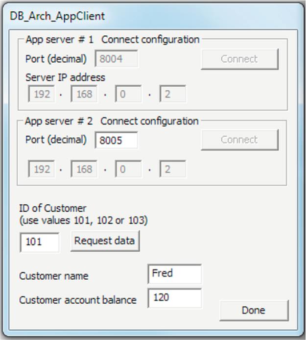
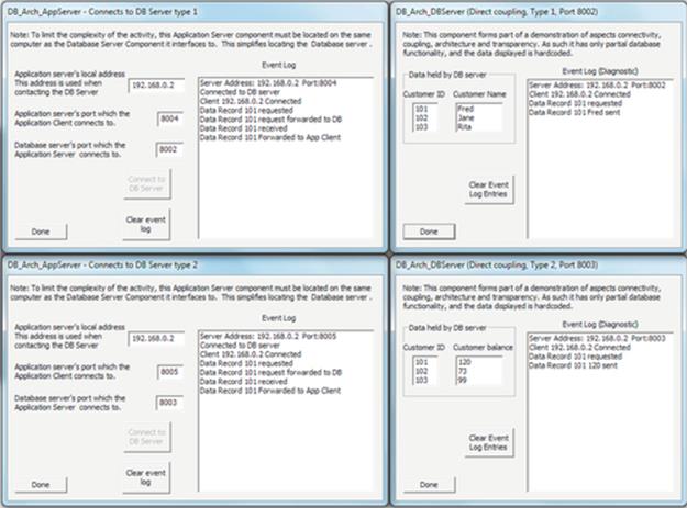
Method Part C: Achieving Distribution Transparency
The third part of this activity is concerned with achieving the transparency goals of distributed systems; in this particular case, we focus on hiding the details of the database services and connectivity such that the client is provided with the illusion that there is a single, locally connected database. This is achieved by refining the middle tier such that the client only has to connect to a single application server that takes care of the connection to the separate databases.
The third configuration uses a modification of the three-tier implementation used in part B. This comprises the following four software components:
DB_Arch_DBServer_DB1_Direct (the implementation of the first of the two database servers), DB_Arch_DBServer_DB2_Direct (the implementation of the second of the two database servers), DB_Arch_AppServer_for_DB1andDB2 (the middle tier that connects to the both of the databases, transparently from the viewpoint of the client), and DB_Arch_AppClient_for_SingleAppServer_DB1andDB2 (a modified client component that connects to the single new middle-tier application server). This configuration corresponds to part (c) of Figure 5.21.
The important difference from the configuration in part B is that now, the client only knows its single application server. It has no knowledge of the way in which the data are organized and cannot tell that the data are retrieved from two different databases. The client is indirectly coupled to the database servers.
The connectivity and behavior are explored in three substeps.
Part C1. Run the client, the application server and the DB1 database server. Request data for one of the customer IDs and observe the result. Notice that the client sends a single request to the application server (the client is unaware of the database configuration). This time, it is the application server that manages the connections to the two database servers, and for robustness, it handles them independently. Therefore, the application server is able to return partial data to the client when only one of the databases is connected.
Part C2. Repeat part C1, this time with only the other database server available.
Part C3. Run the system with all components connected correctly. Request data for one of the customer IDs and observe the result. The single request sent by the client is used by the application server to create a pair of tailored requests, one to each specific database. Responses returned by the two databases are forwarded on by the application server as two separate responses to the client.
Expected Outcome for Part C
Through the experiments in this part of the activity, you should be able to understand the way in which distribution transparency has been added, where it was absent in part B. The client is unaware of the presence of the two different databases and their interfaces. The client is presented with a single-system view in the sense that it connects to the single application server component that provides it all the resources it needs; the design of the client is not concerned with the configuration of the rest of the system.
As with the other parts of the activity, use the diagnostic event logs provided in the application server and the database server components to inspect the behavior in detail.
The screenshots below show the resulting behavior when all four components interact successfully, for part C3 of the activity.
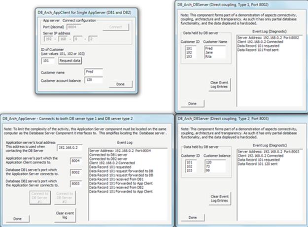
Reflection
This activity provides some insight into the design and operation of two-tier and three-tier applications.
The two-tier configuration used in part A lacks transparency because the client directly connects with the two database servers. The second configuration introduces the third tier, but in such a way as to limit the extent of transparency achieved (access and location transparency are provided). The third configuration reorganizes the middle tier to add distribution transparency such that the client process is shielded from the details of the database organization and is not even aware that there are multiple databases present.
A good exercise to reinforce your understanding of the concepts shown in this activity is to choose any distributed application (some examples are banking, online shopping, and e-commerce) and to sketch outline designs for it, using both the two-tier and the three-tier architectures. Evaluate the designs in terms of their expected transparency, scalability, and flexibility.
example of the importance of transparency. Care has been taken to ensure that the applications developed to support Activity A1 capture both the challenge of accessing multiple distributed resources and the resulting transparency that can be achieved through appropriate design. Note that the actual database functionality that has been implemented in the applications explored in Activity A1 is minimal; it is just sufficient for the examples to be understandable, as the learning outcomes of the activity are focused around the communications and architectural aspects rather than the database itself.
5.9 Peer-to-Peer
The term peer means “with equal standing”; it is often used to describe the relative status of people, so, for example, if you are a student in a particular class, then your classmates are your peers. In software, peers are components that are the same in terms of functionality. The description peer-to-peer suggests that for such an application to reach full functionality, there need to be multiple peer components interacting, although this is dependent on the design of the actual application and the peer components. To place this in context, if the purpose of the application is to facilitate file sharing, then each peer component may have some locally held files that it can share with other peers when connected. If a user runs one instance of the application in the absence of other peers, then only the locally held files will be available; this may still be useful to the user. In contrast to this, consider a peer-to-peer travel information service in which users share local travel information such as news of train delays or traffic jams with other users of the application. The locally held information is already known to the local user (because they create it), so this particular application is only useful when multiple peer components are connected.
5.9.1 Characteristics of Peer-to-Peer Applications
The essence of a peer-to-peer application is that two or more peers connect together to provide a service to the users. Some peer-to-peer applications are designed to work well with just a small number of users (such as media sharing), while for some applications, the utility increases in line with the number of peers connected; for example, some games become increasingly interesting when the number of players reaches a critical mass.
Mechanistically, if peers are symmetrical, then any instance can offer services to the others. This means that in a typical peer-to-peer application, any component can be a service provider or a service requester, at different times depending on circumstances. This is a significant difference from the CS and three-tier models, in which the various components have predetermined roles that are not reversible, for example, a client and server cannot swap roles because the specific behaviors are embedded into the different logic of each component type.
From an interaction viewpoint, peer-to-peer applications tend to rely on automatic discovery and connection among peers. Interactions are sometimes “by chance” due to coexistence of users with related needs. For example, peer-to-peer is popular with mobile devices for game playing and file/media sharing, using wireless links such as Bluetooth for connection. If such applications are enabled on devices, then a connection will be automatically established when the devices are in close proximity to one another. Since it is not generally predictable when peers will come into contact and establish relationships, peer-to-peer applications are often described as having ad hoc interaction behavior. This is in contrast with the CS model, in which the interaction is quite structured and in some senses choreographed at design time (in the sense that a particular client is designed to connect to a particular server, either automatically upon start-up or when the user explicitly requests).
The general characteristics of peer-to-peer applications can be summarized as follows:
• Peers communicate with others to achieve their function (e.g., games, messaging, and file sharing).
• The applications often have limited scope (typically with a single main function) and the requirement for connection to remote “others” on a simple and flexible basis.
• Connectivity is ad hoc (i.e., it can be spontaneous, unplanned, and unstructured).
• Peers can interact with others in any order, at any time. Figure 5.23 captures the essence of this.
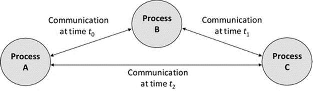
FIGURE 5.23 Peers communicate with different neighbors at different times depending on the application requirements and peer availability.
• Peer-to-peer is well suited to mobile applications on mobile devices.
Figure 5.23 illustrates the dynamic nature of peer-to-peer applications, in which peers may join or leave independently at various times. Therefore, a group of peers may not all be present or connect to each other at the same time; the connections may occur opportunistically as different peers become available.
5.9.2 Complexity of Peer-to-Peer Connectivity
The complexity of peer-to-peer connectivity is potentially much higher than in other architectures, which are more structured. In CS, the number of connections to a given server is one per client, so if there are n clients, there are n connections to the server; thus, we say the interaction complexity is “order n” stated O(n). This is a linear relationship. With this in mind, consider a peer-to-peer scenario where five peers are present and there are multiple connections established in an ad hoc manner among them.2 A possible outcome is shown in Figure 5.24.
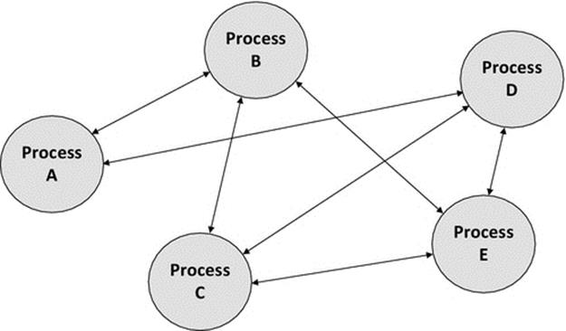
FIGURE 5.24 Ad hoc connectivity in peer-to-peer architectures.
Figure 5.24 shows a configuration of five peers with a total of seven connections between the peers. The maximum number of connections that would occur if all peers connected to each other peer would be ten, in which case each peer would have four connections to other peers. There is a calculation that can be used to determine the maximum number of connections that can occur between a certain number of peers, given in formula (5.1):
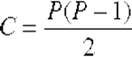 (5.1)
(5.1)
where P is the number of peers present and C is the resulting maximum number of connections. Let's insert some values: for four peers, we get C = (4 * 3)/2 = 6; for five peers, we get C = (5 * 4)/2 = 10; while for six peers, we get C = (6 * 5)/2 = 15, and if we consider ten peers, we get C = (10 * 9)/2 = 45. This is clearly increasing in a steeper-than-linear fashion. Such a pattern of increase is generally described as exponential, and in this particular case, it has order O((n(n − 1))/2), which is derived from formula (5.1). With such a steeply increasing pattern of communication intensity, at some point, the number of connections and the associated communication overheads will impact on the performance of the application, thus limiting scalability. In other words, there is a limit to the scale at which the system can grow to and still operate correctly and responsively.
However, some peer-to-peer systems are designed such that peers connect only to a subset of neighbors (i.e., those other peers that are in communication range). For example, some applications (including some sensor network applications) rely on peer connectivity to form a chain to pass information across a system.
5.9.3 Exploring Peer-to-Peer Behavior
As mentioned above, a popular application for peer-to-peer architectures is media sharing (such as photos and songs) and is especially popular with mobile platforms such as phones and tablets.
A media-sharing peer-to-peer application MediaShare_Peer has been developed to facilitate practical exploration of a peer-to-peer application and is used in Activity A2. The exploration includes aspects of the way in which peer-to-peer systems work, their benefits in terms of flexibility and ad hoc connectivity, and the way in which automatic configuration can be achieved.
Activity A2
Exploration of the Peer-to-Peer Architecture
A media-sharing application is used to explore a number of important aspects of the peer-to-peer architecture.
The application is based on the concept that each user has some music files that they are prepared to share with other users, on a like-for-like basis. The user runs a single peer instance. When there are no other peers available, the user can play only the songs that are held by the local instance. When another peer is detected, the two peers automatically discover each other (in terms of their addresses) and thus form an association (the term connection is avoided because it could imply the use of a connection-oriented transport protocol, such as TCP, when in fact this application uses UDP, partly because of the ability of UDP to broadcast, which is necessary for the automatic peer discovery). The peers then exchange details of the media files they each hold. At this point, the user display is updated to reflect the wider set of resources available to the user (the user can now play any of the music files held on either of the peers).
The demonstration application displays various diagnostic information including an event log, which indicates what is happening behind the scenes, such as the discovery of other peers, and also indicates which specific peer has supplied each music file. This information is included specifically to enhance the learning outcomes of the activity; in a real application, there is no need for the user to see such information.
To avoid unnecessary complexity in the demonstration application, only the resource file names are transferred (i.e., a list of music file filenames) and not the actual music files themselves. In a real implementation, when a user wishes to play a song, the actual song data file would need to be transferred if not already held locally. This simplification does not affect the value of the activity since it is focused on demonstrating the peer discovery and transparency aspects.
Prerequisites
Copy the support materials required by this activity onto your computer; see Activity I1 in Chapter 1.
Learning Outcomes
To gain an understanding of the peer-to-peer architecture
To become familiar with a specific example peer-to-peer application
To appreciate the need for dynamic and automatic peer discovery
To understand one technique for achieving automatic peer discovery
To appreciate the need for transparency in distributed applications
To explore the transparency provision in the demonstration application
The activity is performed in three main stages.
Method Part A: Running a Peer in Isolation
This part of the activity involves running a single instance of the MediaShare_Peer program on a single computer. Note the peer ID number, the list of songs and artists displayed, and the diagnostic event log entries. Close the peer instance and start it again, several times, each time noting the data displayed. You will see that the demonstration application has been designed to generate a unique ID randomly and also to select its local music files randomly, so that the single program can be used to simulate numerous peers with different configurations, without the user having to manually configure it.
Expected Outcome for Part A
This step provides an opportunity to familiarize yourself with the application in the simplest scenario. It also demonstrates two important concepts: Firstly, a single peer operates correctly in isolation (i.e., it does not fail or behave strangely when no other peers are available, but instead operates correctly as a peer-to-peer application that just happens to have only one peer). Secondly, a user sees a list of resources (song files in this case) available for use. Depending on the actual application requirements, it will be generally desired that locally held resources are always available to the local user regardless of the wider configuration of the other peers.
The screenshot below shows a single peer operating in isolation. The media files listed as available are the locally held resources, and thus, a user can access these (i.e., play the soundtracks) without needing any additional components.
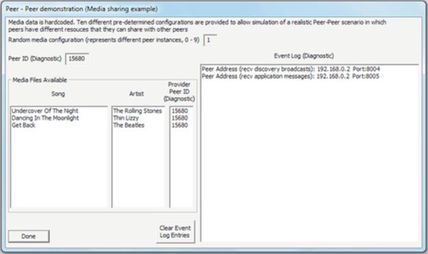
Method Part B: Automatic Peer Discovery
Leaving the local peer instance running (from part A), start another instance on another computer in the same local network (this is important because broadcast communication is used, which is blocked by routers). You can also confirm empirically that only one peer instance can be operated on each computer (try running two copies on one computer). This restriction arises because each peer has to bind to both of the application ports that are used (one for receiving peer self-advertisement messages for automatic peer discovery and one for receiving the peer-to-peer application messages).
Discovery is achieved by each peer sending a self-advertisement message (PEER_SELF_ADVERTISEMENT message type) containing the unique ID of the sending peer, as well as the IP address and port number details that should be used when application messages are sent to that peer. On receipt of these messages, a peer stores the details in its own, locally held known_peers array. This enables the recipient of future self-advertisement messages to distinguish between peers already known to it and new peers.
Discovery of a new peer automatically triggers sending a request message to that peer (REQUEST_MEDIA_LIST message type) causing the peer to respond with a series of data messages (SEND_MEDIA_RECORD message type), each one containing details of one media data item. Note that in the demonstration application, only the song title and artist name are transferred, but in a real media-sharing application, the actual music file would be able to be transferred on demand.
Expected Outcome for Part B
You should see the automatic peer discovery activity in progress, followed by the transfer of available media resources information between the peers. The diagnostic information would not be shown in a real application, since users do not need to know which peers provide which resources, or even be aware of the existence of the remote peers, or see any other information concerning the structure or connectivity of the application itself. Each user would only see the media resources available to them and would be able to access them in the same manner regardless of location, that is, the application provides access and location transparency.
The screenshots below show the two peer instances on two separate computers after they have each discovered the other peer. The first image is of the same peer as shown in part A above (it was left running) and the second image is of the second peer that was started on a different computer during part B of this activity.
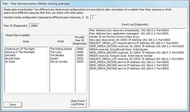
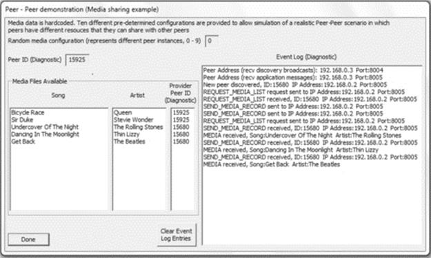
Method Part C: Understanding the Application-Level Protocol
This step involves further investigation to reinforce understanding. In particular, the focus is on the application-level protocol, that is, the sequence of messages passed between the components, the message types, and the message contents.
Part C1. Run the application several times with two peers each time. Look closely at the entries displayed in the activity log. From this, try to map out the application-level protocol (i.e., the message sequence) that is used in the mutual discovery and subsequent mutual exchange of media data between the peers.
Hints: Each peer has the same program logic. The peer discovery and media exchange operate independently in each direction, due to the purposeful symmetrical design that was possible in this case and that makes the application simpler to design, develop, and test. Therefore, it is only necessary to map out the messages necessary for one peer (peer A) to discover another peer (peer B), to request peer B to send its media data, and for peer B to respond to that request by actually sending its data. The same sequence occurs when peer B discovers peer A.
Part C2. Run the application with at least three peers. Check that your mapping of the application-level protocol is still correct in these more complex scenarios.
In addition to empirical evaluation by running the application, you can also examine the application source code, which is provided, to confirm your findings and also to inspect the actual contents of the various message types.
A diagram showing the application-level protocol message sequence is provided in an Appendix at the end of the chapter so that you can check your findings.
Reflection
This activity has supported empirical exploration of two important aspects of peer-to-peer applications: firstly, a demonstration of automatic discovery between components, in which each peer keeps appropriate information in a table so that it can differentiate newly discovered peers from previously known peers and, secondly, an investigation of transparency requirements and transparency provision in distributed applications. The aspects of transparency that are most pertinent in this particular application are that the user does not need to know which other peers are present, where they are located, or the mapping of which music files are held at each peer. In a fully transparent application, the user will see only a list of available resources; if the diagnostic information were removed from the demonstration application's user interface, then this requirement would be satisfied.
These aspects of mechanism and behavior are of fundamental importance to the design of a wide variety of distributed applications. Repeat the experiments and observe the behavior a few more times if necessary until you understand clearly what is happening and how the behavior is achieved.
5.10 Distributed Objects
The distinguishing characteristic of the distributed objects approach is that it divides the functionality of an application into many small components (based on the objects in the code), thus allowing them to be distributed in very flexible ways across the available computers.
From the perspective of the number of components created, the distributed objects approach might show some resemblance to the multitier architectures discussed earlier. However, there are important differences in terms of the granularity and the functional basis on which the separation is performed. Object-oriented code separates program logic into functionally related and/or specific data-related sections (the objects). In most applications, components are deployed at a coarser grain than the object level. For example, a client (in a CS or multitier application) may comprise program code that is internally broken down into multiple objects at the code level, but these objects run together as a coherent single process at the client component level and similarly for the server component(s). In contrast, distributed objects target a fine-grained division of functionality when creating the software components, based on partitioning the actual code-level objects into separate components. Therefore, when comparing the distributed objects and multitier approaches, we should generally expect to see the distributed objects implementation comprises a larger number of smaller (or simpler) objects, perhaps each performing only a specific single function.
The component-location emphasis of the two approaches is also different. Multitier architectures are primarily concerned with the software structure and the division of the business logic over the various components, which is fundamentally a design-time concern. The distributed objects approach better supports run-time decisions for the placement of instances of components, as it operates on the level of individual objects and can take into account their specific resource requirements at run time.
However, a main challenge of such fine division of functionality is the number of connections between the components and the amount of communication that occurs. There may be opportunities to improve performance by ensuring that pairs of components that interact intensively are kept located on the same physical computer.
Figure 5.25 provides an illustrative distribution of seven objects across five computers, as part of a distributed banking application. The object location may be dynamic based on resource availability, and the communication relationships between components may change over time; hence, the caption describes the configuration as a snapshot (it may be different at other times). Notice that there can be multiple objects of the same type (such as “Customer account” in the example) as well as objects of different types spread across the system. The figure also shows how the services of one particular object (such as “Authentication” in the example) may be used by several other objects on demand. The objects communicate by making method calls to one another, for example, in order to execute a foreign currency transaction, the “Foreign currency transaction manager” component may need to call methods in the “Exchange rates converter” object.
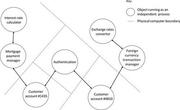
FIGURE 5.25 A distributed objects application; a run-time snapshot.
Figure 5.25 also illustrates some of the differential benefits of the distributed objects architecture compared with multitier. In the example shown, the functionality of an application has been divided across many software components. The benefit of this is the flexibility with which the components can be distributed, for example, to be located based on proximity to specific resources. The location of objects can also be performed on a load balancing basis. For example, if there are several objects (of the same type) in the system that each require a lot of processing resource, the distributed objects approach allows these objects to be executed at different physical sites (processors). Whereas, with the multitier architecture, if all these objects require the same type of processing, they would all have to queue to be processed by a particular server component that provides the requisite function.
Some infrastructure is necessary to support a distributed objects environment. Specific support requirements include a means for objects to be identified uniquely in the system, a means for objects to locate each other, and a means for objects to communicate (make remote method calls to each other). Middleware is commonly used to provide this support; see the next section.
5.11 Middleware: Support for Software Architectures
This section deals with the way in which middleware supports software architectures. A more detailed discussion of the operation of middleware and the ways in which it provides transparency to applications is provided in Chapter 6.
Middleware is essentially a software layer that conceptually sits between processes and the network of computers. It provides to applications the abstraction of a single coherent processing platform, hiding details of the actual physical system including the number of processors and the distribution and location of specific resources.
Middleware provides a number of services to applications, to support component-based software architectures in which many software components are distributed within the system, and need assistance, for example, to locate each other and pass messages. Middleware is very important for dynamic software systems, such as distributed objects, because the location of the actual software components may not be fixed or at least not design time-decided.
5.11.1 Middleware Operation, an Overview
The following discussion of how middleware works focuses on the general principles of operation because there are actually many specific middleware technologies with various differences and special features for particular types of systems (examples include support for mobile computing applications and support for real-time processing).
Middleware provides a unique identifier for each application object that is supported in the system. When these objects are instantiated as running processes, the middleware keeps track of their physical location (i.e., what actual processor they are running on) in a database that itself may be distributed across the various computers in the system (as are the processes that constitute the middleware itself). The middleware may also keep track of the physical location of certain types of resource that the application uses.
Based on its stored information of which objects (running as processes) and resources are present, and where they are located, the middleware provides transparent connectivity services, essential to the operation of the applications in the system. A process can send a message to another process based only on the unique ID of the target process. The middleware uses the process ID to locate the process and deliver the message to it, and it then passes any reply message back to the sender process. This is achieved without either process having to know the actual physical location of the other process, and it operates in the same manner whether the processes are local to each other (on the same processor) or remote. This transparent and dynamic location of objects (processes) also enables movement of objects within the system or for objects to be closed down in one location and subsequently to be run at another location; the middleware will always know the ID of the object and its current location.
It is important to recognize that the middleware plays the role of a communication facilitator. The middleware is not part of any of the applications it supports, but an external service. As such, the middleware does not participate in the business-level connectivity within the application; it does not understand the meaning or content of messages or indeed the specific roles of the various application objects present.
By using the middleware to facilitate connectivity, the objects do not need to have any built-in information concerning the address or location of the other components that they communicate with, and the applications do not need to support their own component discovery mechanisms (an example of such is found in the MediaShare_Peer example discussed earlier). Hence, by using the middleware services, applications can take advantage of run-time dynamic and automated connectivity. This is a form of loose coupling in which the middleware is the intermediary service. This has the benefits of flexibility (because components can be placed on processors based on dynamic resource availability) and robustness (because the application is not dependent on a rigid mapping of components to physical locations). A further important benefit is that the design of the application software is simplified by not having to manage connectivity directly; the value of this benefit increases dramatically for larger applications with many interacting objects.
Figure 5.26 depicts how the presence of the middleware as a virtual layer hides details of the true location of processes and makes them equally accessible regardless of actual location. This means that a process need not know where other processes that it communicates with are physically situated in the system. A process is decoupled from the underlying platform even if it is physically hosted on it. From a logical viewpoint, all processes are equally visible from any platform and all platform resources are equally accessible to all processes.
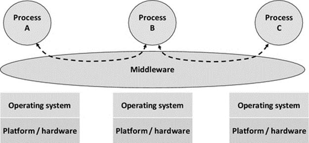
FIGURE 5.26 Overview of middleware.
5.12 System Models of Collective Resources and Computation Resource Provision
There are ongoing evolving trends in the ways that computing resources are provided. This section deals with the various models of computing provision that are important to the developers of distributed applications.
To implement successful distributed applications, in addition to the design of the software architectures of the applications themselves (which is the main concern of this book), there is also a need to consider carefully the design of the systems of computers upon which these applications run. The software developer will probably not be directly involved in the selection of processing hardware and the network technologies that link them together. However, it is nevertheless important for software developers to understand the nature of the various common system models and the impacts these may have on the level of resource available to applications, as well as issues such as robustness and communication latency that may have impacts on the overall run-time behavior.
To fully understand the various models of computation resource provision in the modern context, it is helpful to briefly consider some aspects of the history of computer systems.
Starting with the advent of the PC in the early 1980s, the cost of computing power was suddenly in the reach of most businesses where previously it had been prohibitively expensive. Initially, most applications were stand-alone and were used for the automation of mundane yet important tasks such as managing accounts and stock levels, as well as electronic office activities such as word processing. Local area networks became commonplace within organizations a few years later (towards the end of the 1980s), and this revolutionized the types of applications that were used. Now, it was possible to access resources such as databases and physical devices such as printers that were located at other computers within the system. This initial remote access to resources progressed to distributed computing in which the actual business logic of the applications was spread across multiple components, enabling better use of processing power throughout the system, better efficiency by performing the processing locally to the necessary data resources, and also the ability to share access to centrally held data among many users in scalable ways.
The next step was the widespread availability of connections to the Internet. This allowed high-speed data transfer between sites within organizations and between organizations themselves. Applications such as e-mail and e-commerce and online access to data and services revolutionized the role of the computer in the workplace (and elsewhere).
During this sequence of events, the actual number of computers owned by organizations was growing dramatically, to the point where we are today with almost every employee across a very wide range of job roles having a dedicated computer and relying on the use of that computer to carry out a significant proportion of their job tasks.
In addition to the front-end or access computers, there are also the service provision computers to consider. In the days of stand-alone computing, the resources were all in the one machine. In the days of remote access to resources, via local networks, the computers that hosted resources were essentially the same in terms of hardware configuration and levels of resource as the access computers. In fact, one office user could have remote access to a printer connected to a colleague's computer with exactly the same hardware specification as their own. However, once distributed computing became popular, the platforms that hosted the services needed to be more powerful: they needed more storage space on the hard disks, more memory, faster processors, and faster network links. Organizations became increasingly dependent on these systems, such that they could not tolerate downtime, and thus, expert teams of systems engineers were employed. The service-hosting resources and their support infrastructure, including personnel, became a major cost center for large organizations, requiring specialist management.
In addition, most organizations involved in business, finance, retail, manufacturing, and service provision (such as hospitals and local government), in fact just about all organizations, have complex computer processing needs, requiring many different applications running and using a wide variety of different data resources. Prioritizing among these computing activities to ensure efficient usage of resources can be very complex, and thus, the simple resource provision model of just buying more and more expensive server hosting platform computers becomes inadequate, and a more structured resource base is needed.
As a result of these challenges, several categories of resource provision systems have evolved in which resources are pooled and managed collectively to provide a computing service. The various approaches differently emphasize a number of goals that include increased total computing power available to applications (especially the cluster systems); private application-specific logical grouping of resources to improve the management and efficiency of computing (especially the grid systems); the provision of computing as a service to reduce the cost of ownership of processing and storage (especially the data centers); and large-scale, robust, virtual environments where computing and storage are managed (especially the cloud systems).
5.12.1 Clusters
Cluster computing is based on the use of a dedicated pool of processing units, typically owned by a single organization, and often reserved to run specific applications. The processors are usually loosely connected (i.e., connected by a network; see Section 5.4) and managed with special software so that they are used collectively and are seen by the clients of the cluster as a single system.
5.12.2 Grids
Grid computing is based on physically distributed computer resources used cooperatively to run one or more applications. The resources may be owned by several organizations and the main goal is the efficient processing of specific applications that need access to specific resources, for example, there may be data resources held at various locations that must all be accessed by a particular application. To ensure the performance and efficiency of the applications' execution, these resources can be brought together within a structure with common management and dedicated processors (a grid).
Typically, grids are differentiated from cluster computing in that the former tend to have geographically distributed resources, which are also often heterogeneous and are not limited to physical computing resources but may include application-specific resources such as files and databases, whereas the cluster resources are fundamentally the physical processors themselves and are more localized and likely to be homogeneous to provide a high-performance computing platform.
5.12.3 Data Centers
Data centers are characterized by very large collections of processing and storage resources owned by a service provision company. Processing capacity is offered as a service to organizations that need large pools of computing resource. Typical data centers have thousands of processing units, so an organization can in effect rent as many as needed to run parallel or distributed applications.
The use of data centers reduces the cost of ownership of processing and storage resources because organizations can use what they need, when they need it, instead of having to own and manage their own systems. A particular advantage arises when an organization needs an additional large pool of resource for a short time, and the data center can rent it to them immediately without the time lag and cost of having to set up the resource in-house. The longer-term costs associated with leasing resources rather than owning them may be further compensated by the fact that the user organizations do not need to dedicate large areas of air-conditioned space to locally host services and also do not have to be concerned with expanding systems over time or continually upgrading hardware platforms and performing operating software updates. In addition, they also do not suffer the indirect costs such as workplace disruption and technical staff retraining associated with the hardware and software updates.
5.12.4 Clouds
Cloud computing can be thought of as a set of computing services, including processing and storage, which is provided in a virtualized way by a service provider. The actual processing resources are usually provided by an underlying data center, but the cloud concept provides transparency such that the infrastructure and its configuration are invisible to users.
In addition to the use of cloud facilities for processing, there is currently a lot of emphasis on the storage of bulk data, and this is increasingly popular for use with mobile devices and mobile computing applications. Collections of media files such as videos, songs, and images can be massive in terms of storage requirements and easily exceed the storage available on users' local devices such as tablets and smartphones. The cloud facilities let users upload their files into very large storage spaces (which are relatively huge compared with the capacities of their physical devices) and also offer the advantage of the users being able to access their files from anywhere and also to share them with other users.
The emphasis of cloud computing is towards an extension of personal computing resource (but shifted into a centralized, managed form) in which the cloud storage is allocated permanently to specific users. In contrast, the emphasis of the data center approach is more towards a rentable on-demand computing service. In some respects, a cloud system can be thought of as a set of services hosted on a data center infrastructure.
5.13 Software Libraries
Simple programs with limited functionality may be developed as a single source file containing the program code. Such programs are becoming increasingly rare as the extent of functionality and complexity of applications rises. Additional complexities arise from aspects that include multiple platform support, connectivity with other components, and user customization. There is also a growing trend for software components to have increasing inbuilt intelligence or smartness to deal with situations dynamically. Such applications can be very complex, and it is not feasible to write them as single programs. Some highly functional software, such as electronic office applications, as well as the operating systems themselves can reach hundreds of thousands of lines of code; and it is very likely in such cases that they are developed by large teams of developers. There are many applications for which it is unlikely that any single developer fully understands every single line of code and its purpose within the application itself.
A library is a collection of program functions that are related in some way. This could be a specific type of software functionality (such as a mathematics library, which will contain pretested methods for a variety of mathematical functions including trigonometry, computation of square roots, matrix calculations, and many more) or relating to interfacing to a specific hardware device, such as a security camera (in which case the library would have methods to support pan, tilt, and zoom actions on the camera). As a further example, a data encryption library will contain functions to perform encryption and also to perform decryption of data.
Libraries are a key requirement to manage the complexity of software development and also to manage the development costs, especially in terms of the time requirement. Developing all functionality from scratch simply is not a realistic option in most projects. As an example of how important and commonplace libraries are, consider the very simple C++ program “Adder” that was first seen in Chapter 2; the code for this program is shown in Figure 5.27.
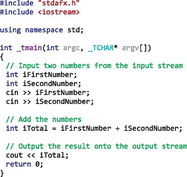
FIGURE 5.27 A very simple program that uses a library.
Figure 5.27 illustrates the point that even the simplest of programs rely on libraries. I have written the code to input two numbers; add them together and output the result; this was very easy. However, if I had to write a program that did exactly as I have described, from scratch without using any library code, then it would a more complex task. Look closely at the program code listing, and you will see evidence of the use of a library. There are two specific clues here. Firstly, the statement “#include<iostream>” indicates that I have included a C++ header file, which contains the declarations of some methods; in this case, they are specifically related to the use of the input and output streams (the way these operate was discussed in Chapter 2). The second clue is the statement “using namespace std” that indicates to the compiler that the set of functionalities provided within the namespace (effectively library) called std can be used, without having to place “std::” in front of each call. If this statement is removed, the compiler complains about the use of the cin and cout methods. What is happening here is that the iostream header file contains the definitions of the cin and cout methods, and the actual implementation of these is provided in the std library. Instead of incorporating the namespace at the program level, I could state the namespace explicitly in the code statements in the form std::cin and std::cout, as in the alternative version of the program shown in Figure 5.28.
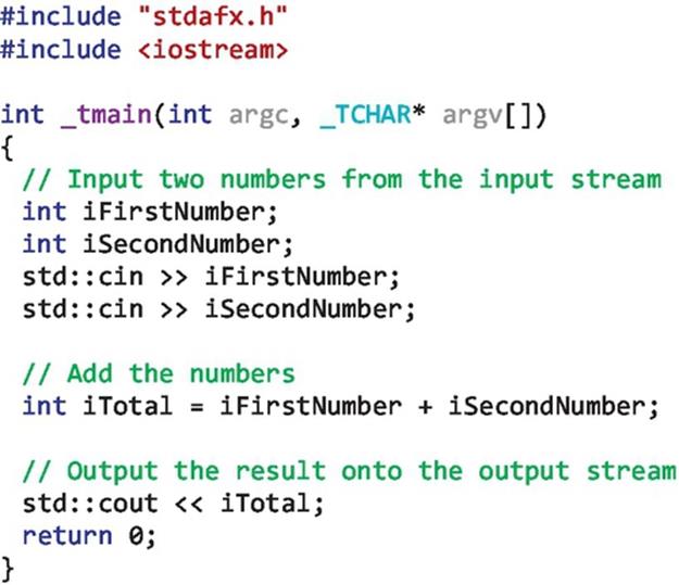
FIGURE 5.28 Emphasis of the use of library methods.
Figure 5.28 provides a code listing that is exactly equivalent in logic and function to the one shown in Figure 5.27, but it has been modified to emphasize the use of the std namespace. The use of this library is significant because the seemingly innocuous cin and cout methods hide a lot of complexity that I do not have time to study and replicate (and test, in all sorts of input and output data combinations) when developing my applications. The use of the library has saved me time and made my code more robust.
Libraries are a generic concept supported in almost all languages. Java provides a comprehensive set of standard class libraries, the Java class library (JCL), which is organized in the form of packages (each having a specific functional theme, e.g., sockets programming or input/output functions). “Import” statements are used to signal which specific library packages are to be used within a particular program. The .NET Framework class library is part of the Microsoft .NET Framework Software Development Kit (SDK). This library is supported for a number of popular languages including Visual Basic, C#, and C++/CLI (C++ with the Common Language Infrastructure). To incorporate a particular library into a specific program, Visual Basic uses the “Imports [library name]” clause, C# has the “using [library name]” clause, and C++ has “using namespace [library name].”
Libraries can evolve alongside an application. In particular, when some parts of one application are needed for use in another application, the common parts can be separated off into a library. This not only greatly speeds up the development of the second application but also ensures consistency between the common functionalities of all the applications that use the newly created library.
The main motivations for the use of libraries can be summarized as follows:
• The need to divide code into modules for development and testing purposes.
• The need to reuse code to reduce development time and increase the robustness of applications.
• The need to reuse code to achieve standardized behavior. For example, the use of a method from a standard mathematics library is safer from a correctness viewpoint than a home-grown method. For a second example, using the same user interface libraries across a suite of applications enables maintaining a consistent look and feel to the applications.
• The need to be able to support variants of applications. For example, to achieve the same business logic functionality across several versions of an application that use different IO devices, just the IO-related libraries can be swapped, minimizing the disruption to the application-level code.
The need for refactoring. It is typical that the first working version of a program is not optimal in terms of clear structure and code brevity. Good requirements analysis and design stages of the life cycle help define a good basic structure, but there is usually room for refinement. Common reasons for refactoring are to group together related methods (those that perform related functions or manipulate the same set of data) into new classes and also to subdivide large methods into smaller ones, making the code more modular and readable and thus easier to maintain.
Duplication of code is undesirable because it increases the bulk of a program, not only making it more difficult to verify and test but also reducing readability. In addition, if a particular piece of functionality is repeated several times in the same program and a change to that functionality is needed, the change must be performed the same in all of the duplicate sections; this is costly and error-prone. Refactoring is often performed to remove duplicate sections of code. For example, suppose there is a small section of three lines of code that performs a particular calculation within an application. This calculation is needed in three different parts of the program logic, so the original developer had copied the already tested three-line section to the additional two places in the code. If the nature of the calculation changes (consider an accounting application, being kept up-to-date in line with changing government legislation and tax rules), then it is necessary to change the code. Difficult-to-detect errors will creep in unless all three copies of the function are updated identically. Refactoring resolves this problem by placing the critical three-line section of code into a new method with a meaningful name that succinctly describes what the method does. The new method is then called from the three places in the program where the three copies of the code were located. In this way, the duplication is removed.
5.13.1 Software Library Case Example
The peer-to-peer media-sharing application will be used as a case example for the creation of a software library. This case example will approach the task of creating a software library using a real application that readers will be familiar with and going through the same typical sequence of steps that a software developer would follow.
A seasoned software developer will see application code in a different way to how a novice sees it. The original sample code for the peer-to-peer media-sharing application provides a good example. A novice might look at the code and be content with the fact that the various methods and variables are meaningfully named so as to make the code easy to understand (such features are termed “self-documenting features” and should be part of everyday practice). Where more explanation is needed, comments have been added into the code source. These contain enough detail to explain any complex functionality or to give the reader a hint as to why a particular section of code was designed in a certain way or perhaps why a sequence of steps are carried out in a particular order. However, it is also important to not have too many comments; otherwise, the important ones don't stand out and the readability of the code goes down instead of up. When they run the code, it works as they expect (from having studied the code) and so the novice developer is satisfied.
However, a seasoned software developer would look at the code and think that it needs “refactoring,” which basically means that there are opportunities to improve the structure of the code by further dividing into additional methods and possibly even creating additional classes. To put this into context, part of the application code is shown in Figure 5.29.
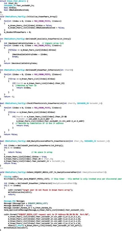
FIGURE 5.29 Sections of the original peer-to-peer media-sharing application source code.
Figure 5.29 shows a sample of the original source code for the MediaShare_Peer application. Three sections of code have been selected (in each case separated by a line of three dots) to illustrate the way the functionality related to managing peer discovery data was merged into the main application class in the original version of the MediaShare_Peer application.
5.13.1.1 A Brief Description of the Original Code
The first section of code shown in Figure 5.29 shows the format of the data structure used to hold details of each discovered peer. Peers are identified by their IP address and port number (the SOCKADDR_IN structure), combined with a randomly chosen ID, which is generated upon the process' start-up. The InUse flag is necessary because a list of these structures is maintained dynamically and it is important that details of a newly discovered peer do not overwrite a currently used instance of the array (consider the behavior of the peer discovery function when there are many peers joining and leaving the application dynamically). The MediaDataReceived flag is used so that each known peer is only asked for details of its media resources until it has provided them.
The next section of code shows five methods that are all related to the maintenance of and access to the data concerning the list of known peers. This is a very important subarea of functionality of the application; data concerned with known peers are used not only in the peer discovery behavior but also in the logic controlling the sending of messages and the processing of received messages.
The third section of code shown in Figure 5.29 shows an example of the way the data concerning known peers are used in the sending of one of the message types: REQUEST_MEDIA_LIST. Firstly, the index of the data entry for the particular target peer is retrieved from the array of structures via one of the methods GetIndexOf_KnownPeer_InPeersList (shown in the earlier code section) using the peer's ID as a search term. The address of the target peer is then retrieved from the array of structures, accessed directly using the peer's index position in the list. Later in the same code section, data from the array are accessed directly when providing diagnostic output indicating the address and port number the message was sent to.
The full program code for the MediaShare_Peer application is available as part of the book's accompanying resources.
5.13.1.2 Refactoring Example for the MediaShare_Peer Application
A partial refactoring of the MediaShare_Peer application is performed to illustrate some of the refactoring concepts in practice. The refactoring focuses on the functionality associated with dealing with managing peer discovery data as was shown in Figure 5.29. The refactoring also serves as a precursor step to separating the code into an application-specific part and a software library that can be reused by other applications that have similar requirements with regard to dynamic peer discovery.
The steps taken for this particular refactoring exercise were the following:
1. Identify a group of methods that are related in terms of the functionality they perform and also in terms of the data items they manipulate.
2. Create a new class called CKnownPeers.
3. Move the identified methods into the new class. Move the class-specific data item (the array of KnownPeers structures) into the new class, as a member variable.
4. Map the new CKnownPeers class into the remaining application logic, by placing calls to the new class' constructor and methods to replace the previously direct access to the data items.
5. Test carefully; the pre- and postrefactoring versions of the application should have identical behavior at the application level. Note that refactoring is not intended to change behavior or to fix errors, so even though the internal architecture of the code has changed, the business functionality should not. If there are any resultant differences in behavior, then the refactoring is incorrect.
Figure 5.30 contains two sections of the code of the new class created in the refactoring process, and the sections are separated by the row of three dots. The first section of code is the class definition from the C header file KnownPeers.h. This defines the class in terms of its member functions and data items. Zcore to the operation of this class. The second section of code shows part of the implementation of the class. The class header file is included, followed by definitions of two of the class methods, the first of these being the constructor.
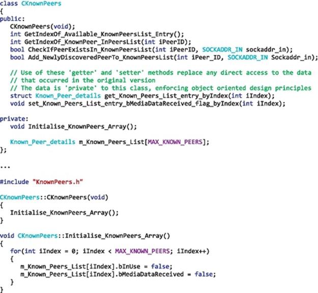
FIGURE 5.30 The new CKnownPeers class extracted by refactoring.
Figure 5.31 shows some aspects of the mapping between the two classes. The main application class still contains the application-specific logic. This class contains a member variable m_pKnownPeers, which is actually an object instance of the new CKnownPeers class (see the first section of code in the figure). The m_pKnownPeers is initialized by calling the class constructor within the outer class' constructor (the second section of code in the figure). From this point onward, the methods of the m_pKnownPeers object can be called.
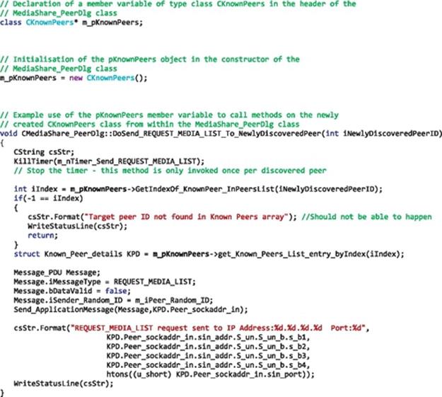
FIGURE 5.31 Mapping between the main application class and the KnownPeers class.
The third section of code in Figure 5.31 shows the new version of the DoSend_REQUEST_MEDIA_LIST_To_NewlyDiscoveredPeer method, which uses the methods of the new class to indirectly access the KnowPeers data; the occurrences of the m_pKnownPeers variable have been highlighted (compare with the version shown in Figure 5.29).
5.13.1.3 Library Example for the MediaShare_Peer Application
Common code (which is used by multiple applications) or code with some specific bounded functionality can be extracted from application code into a library. It is very important that the separation between the application-specific code and the library code is performed along a clear boundary and should not cut across classes, for example.
The refactoring described above has created an additional class with specialized functionality associated with the management of peer discovery data. This functionality is quite clearly differentiated from the application-specific functionality remaining in the main application class and is potentially useful to many applications so it is an ideal candidate for separation into a software library to promote reuse.
From this starting point, the creation of a software library is straightforward. First of all, a new software project is created, and the new class is moved across from the original project into the new one. The compiler must be configured to create a library rather than an executable application. This is important because of the way in which the resulting library file will be used. It does not have its own entry point, for example, so it cannot be run as a separate process. Instead, the library will be linked in to applications after their own code has been compiled.
The library is compiled, creating a file with a .lib extension. For the specific example described here, the file name is DemonstrationLibrary_for_MediaShare_Peer.lib (the project and source codes are available as part of the resources that accompany the book).
The application project no longer contains the CKnownPeers class functionality that was moved across into the library. Thus, the application project needs to link in the library; this is achieved by setting the library as an input file (dependency) of the project in the linker settings.
Figure 5.32 provides a summary representation of the sequence of stages described above, resulting in a software library component that can be linked into one or more applications.
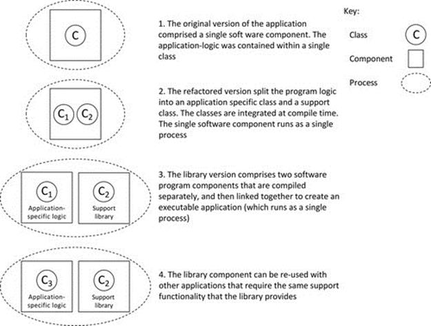
FIGURE 5.32 Diagrammatic representation of the stages of library creation and use.
It is important to reinforce the message that all three versions of the application have the same external behavior. The application logic has been redistributed across software classes and components, but the behavior is identical in each case. To confirm this, the versions were tested for interoperability, simultaneously running peers from the different versions. You can repeat this version cross testing yourself, as all the versions of the code are available in the accompanying resources.
5.13.2 Static Linking and Dynamic Linking
Libraries are linked to application source code in two main ways: statically, where the linking is performed at the component build stage (typically, this is immediately after compilation) and a self-contained executable is created and, dynamically, where the linking is postponed to run time (the linking is performed when the component is run as a process).
5.13.2.1 Static Linking
Static linking is performed when a software component is built (i.e., when the executable file is created). The compiler checks the syntax of the code and creates an intermediate code representation of the program. The linker then includes all necessary library code into the binary image (the executable file). This can increase the size of the resulting executable file significantly, although many optimized linkers only add in the actually used fragments of code from the library (only the implementations of the methods actually referenced in the application source code).
5.13.2.2 Dynamic Linking
Dynamic linking is performed at run time and uses a special variation of a library format called dynamic link library (DLL). This approach is very popular with Microsoft operating systems and came about to limit the size of application executable files and also their run-time images. The approach is advantageous when multiple applications run in the same system and require the same library, because the operating system reads the DLL file into memory and holds its image, separately to the images of the two or more application processes, such that each can call sections of code from the library as necessary. The more applications using the same DLL, the more memory savings that are made. However, if only a single application is using the DLL, there are no space savings because the combined size of the application executable file and the DLL file will take up approximately the same space on the secondary storage (such as hard disk) as the single application with the static library prelinked in. Also, since both parts need to be held in memory at run time, they will require approximately the same combined memory as the equivalent statically linked process would.
5.13.2.3 Trade-Offs Between Static and Dynamic Libraries
The executable file is larger when static linking is used than with dynamic linking. The size difference can be significant for large applications and impacts the storage space requirements, the time taken to transmit the file over a network, and also the amount of time required to load the file as the first step in execution.
The memory image size is larger for processes where the libraries have been statically linked; however, a process that uses dynamic linking still needs access to the library code. Therefore, the DLL must also be loaded into memory, evening out the gains when it is used by only a single process, but potentially saving a lot of memory space when many applications are sharing the same DLL image.
Dynamic linking can be used to achieve deployment-time configurability, in which there are different versions of the same DLL but with different functionality. The method names in the library will be the same, such that the application code can be linked with either version and operate correctly. This then allows some control over the way the application operates by changing which version of the DLL is present and without changing the application code or the executable image. However, DLL versioning can be problematic. Most applications are released as particular build versions, which have been carefully tested and are found to be stable, for example, a new release may be issued after some upgrades have been done. Similarly, DLLs can undergo upgrades and also have version numbers. Having two interdependent component types (one application and one DLL) that are each versioned separately over time can lead to complex run-time mismatches. If a method name in one of the components has changed, or the set of passed parameters is different, then the application either will not run or may crash when the problem call is made. If the changes concern only logic within a library method, then the application may appear to work correctly but return the wrong result. To put the problem into context, consider an application that has an initial release version 1.1, which works perfectly with its DLL version 1.1. After some months, there have been three more versions of the application (versions 1.2, 1.3, and 2.0) and five more versions of the DLL (versions 1.2, 1.3a, 1.3b, 2.0, and 2.1). It is quite likely that there are numerous combinations that work fine, some that have not occurred yet so the outcome is unknown (but considered unsafe), and some that definitely do not work. If you add into the scenario the existence of hundreds of customer sites each with their own technical teams performing system updates, you can start to see some aspects of the versioning challenges that can occur with multicomponent software projects. The possibility of such problems increases the testing burden, to ensure that deployed system images contain only valid combinations of the components. An undesirable situation that could arise is the need to keep multiple backdated DLL versions available to ensure that whatever version of a particular application is installed, it can be run correctly.
The DLL may be omitted from a target computer. Similarly to the problem above, the external DLL requirements of applications must be taken into account when installing the applications. A frustrating situation arises when the application runs perfectly on the development computer (which obviously has the DLL present) but then does not run when ported to another computer because the DLL is not present at that site. This situation is usually easy to fix on a small scale but adds to the overall cost of systems maintenance.
Statically linked applications are self-contained; the library code has been merged in to create a single executable file with no external dependencies. This is robust because it avoids the issues of DLL omission or DLL version mismatch.
5.13.3 Language-Dependent Feature: The C/C++ Header File
The C and C++ languages have a header file type as well as the source code file type. The use of the header file type can improve the internal code architecture of individual components and help ensure consistency across multiple components of a distributed application; hence, it is included in this chapter.
The header file is used to hold definitions of things, as opposed to implementation details. Well-structured C++ code will be divided into a number of classes, each class having one source file (with a .cpp filename extension) and one header file (with a .h filename extension). The class header file will contain the definition of the class and its methods and will declare any class-level member variables. The class header file may also contain the definitions of constants, structures, enumerations, and other constructs used in the class. There can also be additional header files, that is, ones that are not related to any specific class. These can be part of the language itself (e.g., related to the use of libraries, as with the afxsock.h header depicted in Figure 5.34, necessary because the application uses the sockets library) or can contain application-wide definitions that are used across several components. Figure 5.33 illustrates the way in which header files may be used for multiple purposes in an application.
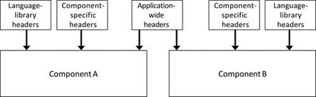
FIGURE 5.33 Use of header files when building distributed applications.
Figure 5.33 illustrates some common uses of header files to provide structure to the source code of a distributed application. Language library header files relate to the inclusion of library routines (e.g., the sockets API library); they contain the declarations of the routines, which are needed by the compiler at compile time in order that the syntax can be checked. For example, even though the actual libraries are not linked by the compiler, it needs to ensure that the various methods that have been used from a particular library have been used correctly, with the appropriate syntax, the requisite number of and types of parameters, etc. Component-specific header files provide the definitions for the implementation classes (the application-specific functionality). Application-wide headers can be used to provide global definitions that are compiled into each of the components and thus are very important for ensuring consistency in the ways that certain related components behave. A good example of this is in the definition of message types and message formats (PDUs; see Chapter 4) that must be the same for each component so that messages are interpreted correctly. In the application shown in Figure 5.33, each of the components A and B will be compiled separately, but the same application-wide header files will be used in both compilations.
Figure 5.34 puts the use of header files into a specific use-case scenario, using the three-tier database application discussed and used in Activity A1 earlier. For each component, only the main class name is shown to avoid unnecessary complexity, but otherwise, this figure accurately reflects the software architecture at the component level. The application comprises three different software components (application client, application server, and database server), which are each compiled to a separate executable file and each run as a separate process. Since the three components are part of the same application, they need to have unambiguous definitions of message formats, message-type identifiers, and the predefined application port numbers. This is achieved by placing these definitions in the file DB_Arch_General.h and including it into all three compilations. The contents of this header file are shown in Figure 5.35.
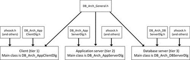
FIGURE 5.34 Header file usage example, a three-tier database application.
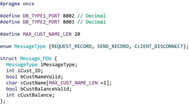
FIGURE 5.35 The contents of the header file DB_Arch_General.h from Figure 5.34.
The contents of the application-wide header file DB_Arch_General.h are shown in Figure 5.35. This file provides important definitions that must be consistent for all of the application components. If a new message type were to be added to the application to extend functionality, then adding it into the enumeration provided in this one header file would ensure that it is defined the same for all of the components. Similarly, if the new message type also required an additional field be added to the message PDU, adding it in the structure defined here will have an application-wide effect.
5.14 Hardware Virtualization
In order to explain hardware virtualization in a clear and accessible way, it is first necessary to briefly revisit the concepts of nonvirtualized (some may say “traditional”) computing.
The nonvirtualized model of computing is that each computer has an operating system installed and the operating system has a scheduler component that runs processes, so that the processes can use the resources of the computer (this aspect was discussed in depth in Chapter 2). The operating system hides some aspects of the hardware platform's configuration. One very important aspect of this is resource management that is done to ensure that resources are used efficiently (e.g., each process may only be given access to a particular fraction of the entire system memory space, thus allowing multiple processes to run concurrently without interference). The operating system also isolates application processes from physical devices, a particular example discussed in Chapter 2 was the way in which input and output streams are managed by the operating system so that the processes do not actually directly manipulate the IO devices. This operating system management of devices has two important benefits, one being that the various IO devices can be used by multiple processes without conflict and the other being that the specific interface details of individual IO devices are abstracted away at the program level. So, for example, a programmer can write an input or output statement without knowing the type or size of screen, the type of keyboard, etc., that is present and also the program once written will work correctly even if the IO devices are changed in the future.
Hardware virtualization is the term used to describe the addition of a software layer, which sits on the real hardware platform and acts as though it is actually the platform itself. The software layer is called a virtual machine. The VM is able to execute processes in the same way as the operating system would in the traditional (nonvirtualized) model of computing described above.
In some ways, hardware virtualization can be considered an extension of the isolation and transparency aspects provided to processes by operating systems. However, hardware virtualization is motivated by the need to support flexible retasking and reconfiguration of computers, which can involve replacing the entire software image on the computer, including the operating system (or running two different operating systems on the same computer) and performing these changes in a short time frame.
In order to appreciate the significance of the additional flexibility represented by the VM approach, over the nonvirtualized approach, it is necessary to consider the high degrees of heterogeneity that occur in modern distributed systems. Heterogeneity manifests in many forms, as was discussed earlier in this chapter. The existence of so many different hardware platforms, operating systems, and resource configurations adds a lot of complexity to the management of computer systems. Users need to run a variety of applications that may require different configuration of resources or even different operating systems, yet it is not feasible to reinstall the operating system in order to run a particular application or to provide each user with several differently configured computers in order to allow them to run the various different applications they need throughout the working day. The problem is more significant for the owners of large-scale computing resources due to the cost of purchasing equipment and the potentially even greater ongoing management costs associated with the man power needed to support users with such requirements. Data centers in particular need a way to automatically deal with issues of heterogeneity, because they rent out their computing resources to numerous different customers, hence multiplying the numbers of different resource configurations likely to be needed. Clearly, data centers cannot meet this demand in a cost-effective and timely manner with specifically configured physical platforms because they would have to have a much larger total number of computers and a very large technical support team.
5.14.1 Virtual Machines
VMs have become an essential tool to overcome the challenge of frequent reconfiguration of platforms to meet users' diverse needs, which arise in part from the various forms of heterogeneity in modern systems and also because of the very wide variety of applications of computing with ever-increasing extent of functionality and the inevitable accompanying complexity.
A VM is a process that runs on the physical computer and presents an interface to application process, which mimics that of the real computer. The VM thus isolates the application processes from the physical machine. For example, a computer that is running one particular operating system (such as Microsoft Windows) may host a VM that emulates a computer running a different operating system such as Linux, in which case Linux applications will run on the VM and will behave the same as if on a real computer with the genuine Linux operating system installed. The VM is the process that the Windows scheduler deals with; see Figure 5.36.
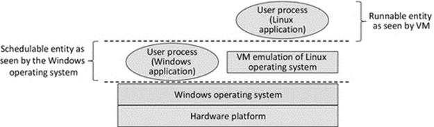
FIGURE 5.36 Using a VM to emulate additional operating systems on a single computer.
Figure 5.36 shows how a VM can be run on top of a conventional operating system such as Microsoft Windows, to enable nonnative applications to run. In other words, the VM provides an emulation of a different operating system (Linux in this case) and thus allows applications designed for that operating system to run.
For environments where computers need to be configured with different VMs, a VM manager or hypervisor can be used. The hypervisor creates and runs VMs as needed. The need for automated VM management can be understood by considering a data center scenario: each particular customer wishes to run their specific application, which requires a certain run-time system (i.e., the operating system and various needed services). Instead of having to provision the computer for each customer by installing the appropriate operating system and then each of the required services and then the various components of the customer's specific application, which involves many separate stages and is thus time-consuming and subject to failure of individual steps, the hypervisor can generate the appropriate VM image in a single step.
Type 1 hypervisors run directly on the computer hardware (i.e., they replace the operating system), whereas type 2 hypervisors are hosted by an operating system (i.e., they run on top of the operating system in the same way that the VM runs on top of the operating system in Figure 5.36).
5.14.2 Java Virtual Machine
Java implements a specific VM, the JVM, which offers a consistent interface to Java programs regardless of the actual operating system and architecture. Java programs actually run in the JVM and not directly on the underlying platform; this means that Java programs are inherently portable. This concept is illustrated with the aid of Figures 5.37 and 5.38.
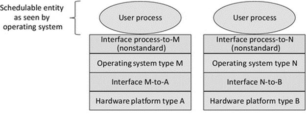
FIGURE 5.37 The conventional process-to-operating system interface is operating system-dependent.
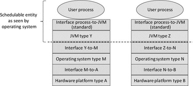
FIGURE 5.38 The JVM standard interface to processes.
Figure 5.37 shows that the conventional process run-time environment (the process-to-operating system interface) is provided differently by each operating system (as explained in detail in Section 5.3 earlier). This means that applications must be built specifically for their target operating system, and therefore, executables are not transferrable across operating systems.
Figure 5.38 shows that the JVM provides a standard interface to application processes, regardless of the underlying system comprising any combination of operating system and hardware platform. This is achieved by using a special universal code format called the Java bytecode, which is a simple and standardized representation of the program logic with a low-level format that is similar to assembly language in some respects. The end result is that the user process in left part of Figure 5.38 will run correctly in the system shown in the right of Figure 5.38 without any modification or recompilation.
The JVM itself does have to be built specifically for the platform on which it runs, hence the differences in the JVM type, and the operating system interface to the JVM (the layer below the JVM), in Figure 5.38. The operating system sees the JVM as the schedulable entity; in other words, the JVM itself is the process that runs directly on top of the operating system and not the Java application.
5.15 Static and Dynamic Configurations
The issue of static versus dynamic software configurations has been touched upon in several earlier sections, including Section 5.5.1 and also in Section 5.9 where ad hoc application configurations were discussed and explored in an activity. Later in this chapter,Section 5.16.1 also examines dynamic configuration of a service to mask failure of an individual server instance.
This section brings together the various issues associated with the choice between static and dynamic configurations of distributed applications. The main aspects that need to be considered are the way in which components locate each other, the way in which components form connections or at least communicate with each other, and the way in which roles are allocated to individual components in a group (e.g., when there are several instances of a service and a single coordinator is needed).
5.15.1 Static Configuration
Static configuration is achieved by default when building multicomponent applications. If a design fixes the roles of components and the ways in which the components relate to each other, connect to each other, and perform processing as part of the wider application, then you will end up with a static configuration. In such situations, there is no need for any additional services to dynamically map the components together; the one configuration is deemed to suit all situations. If you run the application a number of times, you will always arrive at the same component-to-component mapping.
The identity of software components can be represented in several different ways. Components need unique IDs that can be based, for example, on their IP address or on a URL, the URL being more flexible because it allows for relocation of services while still identifying the service components uniquely. Component IDs can also be system-wide unique identifiers allocated by services such as middleware, specifically for the purpose of mapping components together when messages need to be passed between them.
The essence of static configuration is that components connect to one another based on design time-decided mappings. This is most obvious if a direct reference to the identity of one component is built into another and used as the basis of forming connections or at least sending messages.
Statically configured applications are generally simpler to develop and test than their dynamically configured counterparts. However, they rely on complete design-time knowledge of their run-time behavior and also the environment in which they run. This is very difficult to confirm unless the application has very limited functional scope and comprises a small number of components. This also means that statically configured systems may need more frequent version updates to deal with any changes in the run-time environment, because each specific configuration is fixed for a particular setting. Perhaps, the most significant limitation of static configuration is that it is inflexible with respect to dynamic events such as component failures or failure of the specifically addressed platform where a resource is located.
5.15.2 Dynamic Configuration
Dynamic configuration of distributed applications increases run-time flexibility and potentially improves efficiency and robustness. In the case of efficiency, this is because components can be moved between physical locations to better map onto resource availability, or component requests can be dynamically diverted to different instances of server processes (e.g., to balance the load on a group of processors). Robustness is improved because component-to-component mappings can be adjusted to account for events such as the failure of a specific component; so, for example, if a client is mapped to a particular instance of a service and that instance fails, then the client can be remapped to another instance of the same service. There are mechanisms that can be used to do this automatically.
The essence of dynamic configuration is that components discover one another based on roles rather than component-unique IDs. That is, components know what types of services they require and request connections to components that provide those services without knowing the IDs of those components in advance. Typically, additional services are required to facilitate this, specifically to advertise the services provided by components, or otherwise to find services based on a role description, and to facilitate connectivity between the two processes. Examples of external services that facilitate dynamic discovery and connectivity include name services and middleware.
Some services perform dynamic configuration internally, for example, to balance load or to overcome or mask failures of individual subcomponents of the service. Mechanisms such as election algorithms are often used to automatically select a coordinator of a dynamic group of processes whose membership can change over time, as different nodes join and leave the service cluster. An election algorithm follows several steps: firstly to detect that a particular component has failed, secondly to carry out an election or negotiation among the remaining components to choose a new coordinator, and finally to inform all components of the identity of the new coordinator to suppress additional unnecessary elections. Election algorithms are discussed in detail in Chapter 6. Other mechanisms for dynamic configuration discussed elsewhere in the current chapter include the use of heartbeat messages by which one component informs others of its ongoing presence and health status and service advertisement messages that facilitate automatic discovery of components or the services they offer.
Dynamic configuration mechanisms also facilitate context-aware behavior in systems (see next section).
5.15.3 Context Awareness
Context awareness implies that an application's behavior or configuration takes the operating context into account, that is, it dynamically adjusts its behavior or configuration to suit environmental or operating conditions. This is a complex aspect of systems behavior, which is out of scope for the book generally, but is very briefly introduced here for completeness.
Context is information that enables a system to provide a specific, rather than generic response. To give a very simple example, you ask me the weather forecast for tomorrow and I respond “it will rain.” This is only of use to you if we have previously communicated the location we are referring to (which contextualizes both the question and the answer in this case). One example relating to distributed services concerns the failure of a server instance. The number of remaining servers is a very important context information because if there are still one hundred servers operating, the failure of one is relatively insignificant, but if there are only one, or none remaining, then it is serious and new servers need to be instantiated.
Dynamic configuration mechanisms and context information provide a powerful combination to enable sophisticated and automated reconfiguration responses to events such as sudden load increases or failure of components.
5.16 Nonfunctional Requirements of Distributed Applications
There are a number of common nonfunctional requirements of distributed applications, most of which have already been mentioned several times in various contexts in the book. Here, they are related and differentiated.
Robustness. This is a fundamental requirement of almost all distributed applications, although it can be interpreted in different ways. Robustness in the sense that there are no failures at the component level is unrealistic because no matter how well designed your software is, there are always external factors that can interrupt the operation of a distributed application. Examples include excessive network traffic causing delay or a time-out, a network failure isolating a server from its clients, and a power failure of the computer hosting the server. Therefore, a key approach to robustness is to build in redundancy, that is, to have multiple instances of critical components such that there is no single point of failure (i.e., there is no single component that, if it fails, causes the system itself to fail).
Availability This requirement is concerned with the proportion of time that the application or service is available for use. Some business- or finance-related services can cost their owners very large sums of money for each hour that they are unavailable; consider stock-trading systems, for example. Some systems such as remote monitoring of dangerous environments such as power stations and factory production systems are safety critical, and thus, availability needs to be as near to 100% as possible. You may come across the term “five nines” availability, which means that the goal is for the system to be available 99.999% of the time. Availability and robustness are sometimes confused, but technically, they are different; an example is scheduled maintenance time in which a system is not available, but has not failed. Another example is where a system can support a certain number of users (say, 100). The 101th user connects to the system and is denied service, so the service is not available to him specifically, but it has not failed.
Consistency This is the most important of all of the nonfunctional requirements. If the data in the system do not remain consistent, the system cannot be trusted and so has failed at the highest level. To put this into context with a very simple example, consider a banking application in which customers can transfer money between several of their own accounts online (over the Internet). Suppose a customer has £200 in her current account and £300 in her savings account. She moves £100 from the current account into the savings account. This requires multiple separate updates within the bank's system, possibly involving two different databases and several software components. Suppose the first step (to remove £100 from the current account) succeeds, but the second step (to place it in the savings account) fails; the system has become temporarily inconsistent because the customer's credit has gone from £500 to £400 when the total should have remained at £500. If the system has been designed well, it should automatically detect that this inconsistency has arisen and “roll back” the state of the system to the previous consistent state (in this case the initial balance values).
Performance (or Responsiveness). This is the requirement that a transaction is handled by the system within a certain time frame. For user-driven queries, the reply should be timely in the context of the use of the information. For example, if the application is stock trading, then a response within a second or so is perhaps acceptable, whereas if it is an e-commerce system in which one company is ordering wholesale batches of products from another, a longer delay of several seconds is adequate as the transactions are not so time-critical. See also the discussion on Scheduling for Real-Time systems in Chapter 2.
Consistent performance is also important for user confidence in the system. Variation in response times impacts some aspects of usability, since long delays can frustrate users or lead to input errors (e.g., where a user is uncertain that the system has detected a keystroke and so enters it again, this can lead to duplicate orders, duplicate payments, and so forth).
Scalability. This is the requirement that it should be possible to increase the scale of a system without changing the design. The increase could be in terms of the number of concurrent users supported or throughput (the number of queries or transactions handled per unit of time). Scaling up a system to meet the new demand could involve adding additional instances of components (see Section 5.16.1), placing performance-critical components on more powerful hardware platforms, or redesigning specific bottleneck components in isolation, but should not require a redesign of the overall system architecture or operation.
It is important not to confuse scalability and responsiveness; a lack of scalability as load increases may be the underlying cause of reduced responsiveness, but they are different concerns.
Extensibility It should be possible to extend the functionality of a system without needing to redesign the system itself and without impact on the other nonfunctional requirements, the only permissible exception being that there may be an acceptable trade-off between the addition of new features and a corresponding reduction in scalability as the new features may lead to an increase in communication intensity.
Transparency. This is the requirement that the internal complexities of systems are hidden from users such that they are presented with a simple to use, consistent, and coherent system. This is often cited as the fundamental quality metric for distributed systems.
A general transparency goal is the single-system abstraction such that a user, or a running process that needs access to resources, is presented with a well-designed interface to the system that hides the distribution itself. All resources should appear to be available locally and should be accessed with the same actions regardless if they are truly local or remote. As mentioned in numerous other sections, there are many different flavors of transparency and a wide variety of ways to facilitate it.
Transparency provision is potentially impacted by the design of every component and the way they interact. It should be a main theme of concern during the requirements analysis phase because it is not generally possible to post-fit transparency mechanisms to an inherently nontransparent design.
Usability. This is a general label for a broad set of concerns that overlap several of the other nonfunctional requirements, especially responsiveness and transparency. Usability is also related to some specific technical aspects, such as the quality of user interfaces and consistency in the way information is presented, especially if there are several different user interfaces provided by different components.
In general, the more transparency that is provided, the more usable a system is. This is because users are shielded from having to know technical details of the system in order to use the system. Usability in turn improves overall correctness because with clear, easy to use systems, in which users do not have to follow complex procedures and are not asked to make decisions based on unclear situations, there are fewer mistakes made by users or technical managers.
5.16.1 Replication
Replication is a commonly used technique in distributed systems, not only having the potential to contribute to several of the nonfunctional requirements identified above, most notably robustness, availability, and responsiveness, but also having the potential to disrupt consistency if not implemented appropriately.
This section focuses on the relationships between replication and the nonfunctional requirements of distributed systems. Transparency and mechanistic aspects of replication are discussed further in Chapter 6.
The simplest form of replication is service provision replication where there are multiple server instances, but each supports its own set of clients, so there is no data sharing across the servers. This approach is used to improve availability and responsiveness but does not improve robustness as there is still only one copy of the state of each client session and only one copy of the data used by each client. There is no requirement for data update propagation, but instead, there is a need to direct the clients to servers so as to balance the load across them, since if all clients connect to one server, then the service provision replication has no effect on performance.
Consider the use-case game. Multiple copies of the server could be started at different locations to achieve a simple form of replication without the need for any modification to the current design. This replicates function, but not data or state. Each client would still connect to a specific server instance (identified by its IP address) and thus would only see the other players connected to the same server instance, advertised in the available players list. More users in total could be supported, that is, availability is enhanced, and because users could connect to the geographically nearest server, the network latency may be reduced, increasing responsiveness. However, the clients are associated, via their server, in isolated groups. There is no mechanism to move games between servers or to back up game state at other servers; each client is still dependent on a particular server to hold the game state, so robustness is not improved in regard to active games.
Where replication of data occurs, the extent of performance benefits and the extent of the challenge to manage data and ensure data consistency are related to the data access mode supported, specifically whether data can be modified or is read-only, during transactions. If the replication is of active application state, or of updateable resources, then the additional complexity can be very high due to the need to propagate updates to all copies. This is relatively simpler if only one copy of the shared data is writable by the user application, but even so, there is still a significant challenge of ensuring that copies that go off-line are brought up-to-date correctly when they reappear. There are three common scenarios that occur:
1. The data are read-only at all of the replicas. This could apply to information-provision applications such as an online train timetable system, in which multiple servers could be used to support a great many clients retrieving train journey details simultaneously. However, the data itself can only be modified by a separate system (a management portal not available to the public users). There are no user queries that can cause any data updates. In such cases where the replication is across multiple server instances of read-only resources, then the additional complexity arising from the replication itself is relatively low and the scheme can scale very well.
2. The replication is implemented such that only a single copy of the data is writable and the other copies are readable. The challenges here are ensuring that only one copy of the data really is ever writable at any specific time and also ensuring that all updates to the writable copy are copied promptly and reliably to the other copies. This can work well in applications in which read accesses significantly outnumber write accesses.
3. The replication is implemented such that all copies of the data are writable. This can lead to various issues, including the specific problem of a lost update, where two copies of a particular data value are both modified in parallel. When each of the changes is then propagated across the system, the one that is applied last will overwrite the one that was applied first, that is, the first update has been lost. The lost update problem is significant because it occurs even when all components are functioning correctly, that is, it is not caused by a failure, but rather is an artifact of the system usage and the specific timing of events.
This approach can be very complex to manage and is generally undesirable because in addition to the lost update problem, there a number of ways the system can become inconsistent.
The primary objective when adding replication is to ensure that the system remains consistent under all circumstances and use scenarios. This must always be the case, to ensure the correctness of systems even when the original motivation and purpose for implementing replication are to improve availability, responsiveness, or robustness.3
Figure 5.39 illustrates a simple form of replication in which a single instance of the service (and thus data) is available to users at any given time. This is because all service requests are directed to the master instance of the service, so the backup instance is effectively invisible to users. When a user request causes data held by the server to change, the master instance updates its local copy of the data and also propagates any updates to the backup instance. The backup instance monitors the presence of the master instance. This could, for example, be facilitated by the master instance sending a status massage to the backup instance periodically, in which case if these messages cease, the backup instance becomes aware that the master instance has failed. Figure 5.39 shows the situation when both instances of the service are healthy and updates are performed on both replicas of the data. The mechanics of step 1 (parts a and b) in Figure 5.39 could be based on multicast or directed broadcast or by using a group communication mechanism, which is discussed in Chapter 6.
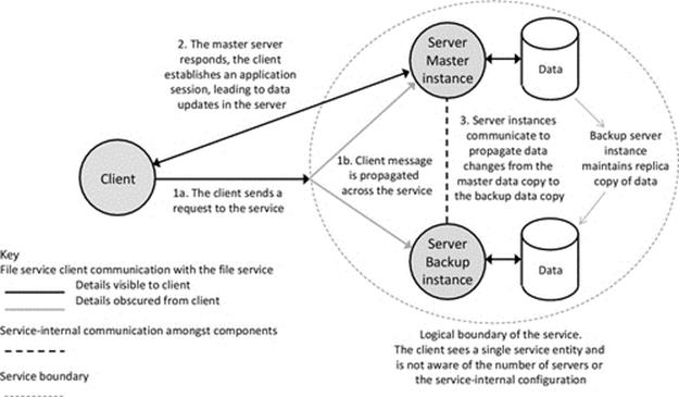
FIGURE 5.39 Master-backup data replication of active application state and data.
Figure 5.40 illustrates the adaptation of the configuration of the replicated service that occurs when the master server instance has failed. Initially, there will be a period in which the service is unavailable, because the backup instance has not yet detected the previous master's failure, so has not taken over the master role. Once the backup server instance detects that the master has failed, it takes over as master (this is also described as being promoted to master state). From this point onward, service requests are dealt with by this server instance.
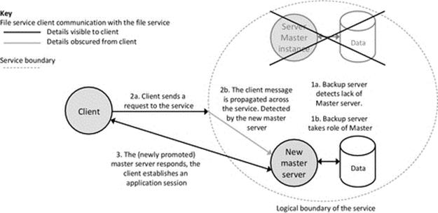
FIGURE 5.40 Backup-promotion scenario in master-backup data replication.
The mechanism by which the failure of the master instance is detected must itself be reliable. The detection is usually based on some form of heartbeat mechanism such that the healthy master server sends a periodic massage to inform the backup that it is still healthy. This may be omitted when updates are occurring regularly (because the update messages also serve the purpose of informing the backup that the master is still healthy, without adding any additional communication) and only switched on if the interval between updates exceeds some threshold. Thus, the backup copy should not wait more than a specified period without a message from the master. However, messages can be lost or delayed by the network itself, and thus, it is not safe to trigger the backup copy switching over on the omission of a single heartbeat message; perhaps, three omitted messages in sequence are appropriate in some systems. The configuration of the heartbeat scheme (which includes the interval between messages and the number of messages that must be missed in sequence to serve as confirmation that the master has failed) must be tuned for the specific application as it represents a three-way trade-off between the responsiveness of the backup system, the message overheads to maintain the backup system, and also the risk of a false alarm, which introduces a further risk of data inconsistency if both copies become writable simultaneously.
5.16.2 Semantics of Replication
When implementing mechanisms such as replication, it is important to consider carefully the merits of the various alternative ways of achieving the required functionality. For replication, semantics are concerned with the actual way the replication mechanisms behave in terms of the way they manipulate the system data. Issues that need to be considered include the following:
• What should happen when the master copy becomes unavailable, should the backup copy become available for access, or is it maintained only to establish the system consistency once the master server has been repaired?
• If the backup copy is made available (upon master failure), there is the issue as to whether it should be made read-only or read-write; the main concern is that the two copies could get out of sync. This could happen if updates occur at the backup copy, and then, it also fails; when the previous master copy comes back on line, it has no knowledge of the intervening transactions.
• Are the roles of master and backup preassigned or do they arise dynamically from the system behavior (e.g., the most accessed instance may be automatically assigned to be the master instance)? If the roles were preassigned, then what should happen after a master that had failed (and hence the initial backup instance is now acting as master) recovers? Does the original master reclaim its master role, or does it assume backup status?
• Some implementations of replication employ an odd number of server instances (at least three) so that in the event that the copies become out of sync, then a vote can be taken, that is, the correct value is taken to be the majority value. However, there are no absolute guarantees that the majority are correct (it is less likely, but possible that two out of the three missed a particular update). There is also no guarantee that there will even be a majority subset (consider a group of five server instances, in which one has failed and the four remaining are split with two having a particular data value and the other two having a different value).
Figure 5.40 illustrates one of the possible fallback scenarios when the master copy fails. In the approach illustrated, upon detection of master failure, the backup instance promotes itself to master status (i.e., it takes over the role of master). Data consistency is preserved so long as the previous master instance had propagated all data updates to the (then) backup copy, which it should do if it is operating correctly.
5.16.3 An Implementation of Replication
A demonstration application is provided to illustrate the implementation and operation of replication in the context of a simple database application. The same database theme as used in Activity A1 is continued, but in this case, there is a single database that is replicated, instead of two different databases, as used in the earlier activity. In this specific example, the replication has been used to ensure the service is robust against server-process failure. A single master status instance of the service deals with client service requests. The master instance also broadcasts periodic heartbeat messages to signal its presence to other instances of the service. An additional instance can exist, having the status of backup; its role is to monitor the status of the master instance by receiving heartbeat messages. If the absence of three successive heartbeat messages is detected, then the backup instance promotes itself to master status. The master instance of the service propagates any data updates made by the client, to the backup instance, therefore keeping the data held at the backup instance synchronized with the master instance and thus keeping the service consistent. If the backup copy has to take over from the master instance then, the data will be up-to-date and reflect any changes made before the master instance crashed.
In order to show the variety of design choices available, the implementation uses an alternative means of clients locating the service to that shown in Figures 5.39 and 5.40. The technique shown in those examples is based on the client sending a service discovery broadcast message and the master instance of the service responding. Instead, the implementation of the demonstration replicated service uses service advertising in which the master instance of the service sends broadcast messages at regular short intervals of a few seconds. A newly started client must wait to receive a service advertisement message that contains the IP address and port details needed to connect to the service. If the backup server instance elevates itself to master status, it takes over sending the service advertisement broadcasts, so that clients always detect the current master instance of the service. In this implementation, a failed master instance that recovers will take on the status of backup (assuming that another instance now has master status, such as the previous backup instance).
Figure 5.41 shows the service-internal behavior that determines the state of each instance of the replicated database application. The diagram shows the behavior of a single process; each process maintains its own copy of the state transition logic and represents its state internally as a pair of variables. In this case, the state variables that govern the state transition behavior are as follows:
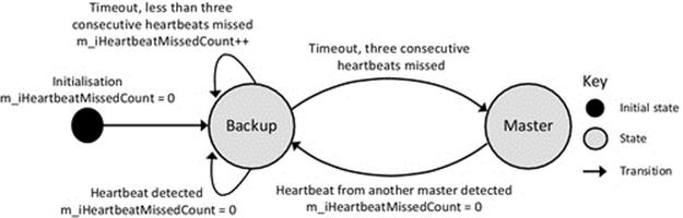
FIGURE 5.41 The state transition diagram of the replicated database demonstration application.
|
m_ServerState {Backup, Master} |
An enumerated type |
|
m_iHeartbeatMissedCount ≥ 0 |
An integer |
Each time a heartbeat is detected within the expected time frame, the m_iHeartbeatMissedCount variable is reset to 0. When a time-out occurs (the heartbeat was not detected in the expected time frame), the variable is incremented. If the variable reaches the value 3, the backup instance elevates itself to master status. There are two ways in which a master status instance can cease to exist; firstly, if it crashes or is purposely removed from the system and, secondly, if it detects any heartbeat messages from another master instance (in which case it demotes itself to backup status). This is a fail-safe mechanism to prevent the coexistence of multiple master instances.
There are two types of communication within the replication demonstration application: communication within the service itself (between the server instances) and communication between the application client and the master instance of the service. Figure 5.42shows the socket-level connectivity between the various components.
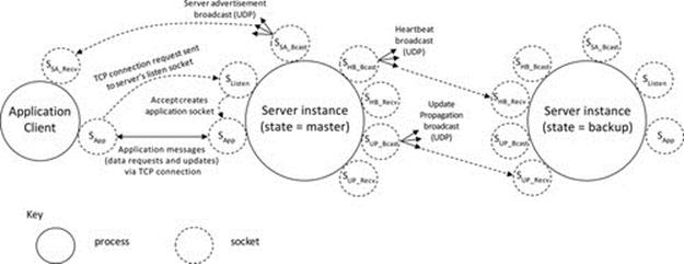
FIGURE 5.42 The socket-level connectivity between the components of the replication service.
Figure 5.42 shows the socket-level communication within the replication demonstration application. The communication between the application client and the master instance of the service is shown to the left. It comprises the server sending service advertisements, which are broadcast over UDP and used by the client to gain the server's address details and thus connect using TCP. The TCP connection is used for all application requests and replies between the client and the server. The communication between the master instance of the service and the backup instance is shown to the right. Both processes have the same sockets, but the broadcast sockets and the TCP sockets used to connect to clients are inactive on whichever instance is in backup state. Only the master instance broadcasts heartbeat messages, which the backup instance receives. When the client has caused an update of the data held by the master instance, the master sends an update propagation message to the backup instance.
The behavior of the replication demonstration application is explored in Activity A3. The full source code is available as part of the book's accompanying resources.
Activity A3
Exploring the Master-Backup Data Replication Mechanism
A replicated database application is used to investigate the behavior of a data replication mechanism, as well as aspects of dynamic service configuration and component role allocation through the use of heartbeat messages, data update propagation between server instances, and service advertisement broadcasts to enable clients to locate the master service instance.
This activity uses the Replication_Client and Replication_Server programs. To simplify the configuration of the software and to ensure that the focus of the experimentation is on the architectural aspects of replication, the database servers actually hold their data in the form of in-memory data tables. The values are initially hard-coded, but can be updated through client requests. Any updates that occur at the master server instance are then propagated to the backup server instance.
During the experiments, observe the diagnostic event information displayed in each component, which provides details of internal behavior.
Prerequisites
Two networked computers are needed because each instance of the service needs to bind to the same set of ports; therefore, they cannot be coresident on the same computer. Since broadcast communication is used, the computers need to be in the same local network.
Learning Outcomes
• To understand the concept of data replication
• To become familiar with a specific replication mechanism
• To explore the behavior of a simple replicated database application
• To explore automatic service configuration and component role allocation
• To explore dynamic service discovery with service advertisement broadcasts
• To explore update propagation
• To gain an appreciation of failure transparency in a practical application setting
The activity is performed in five stages.
Method Part A: Component Self-Configuration and Self-Advertisement (One Server)
This part of the activity is concerned with the self-configuration that occurs when a single server instance of the replicated database service is started.
Start a single copy of the client program Replication_Client and the server program Replication_Server on different computers. The server process initializes itself to backup state. It listens for heartbeat messages, and because it does not detect any (it counts three consecutively missed heartbeats), it elevates itself to master state. Once in master state, it begins to broadcast periodic service advertisements. This is to enable any clients to locate the server.
Initially, the client process does not know the address of the server, so it cannot send a connection request. Notice how it receives a service advertisement message (containing the server's address details), updates its record of the server's address, and then uses this information to automatically connect to the service.
Expected Outcome for Part A
You should see the server initializes itself to backup state, then waits for heartbeat messages and on receiving none, and elevates to master status. At this point, you see it starts to send service advertisement and heartbeat messages.
The client process receives the server advertisement.
The screenshot below shows the server instance initializing to backup state and then elevating to master state, at which point it begins sending heartbeat messages and server advertisement messages.
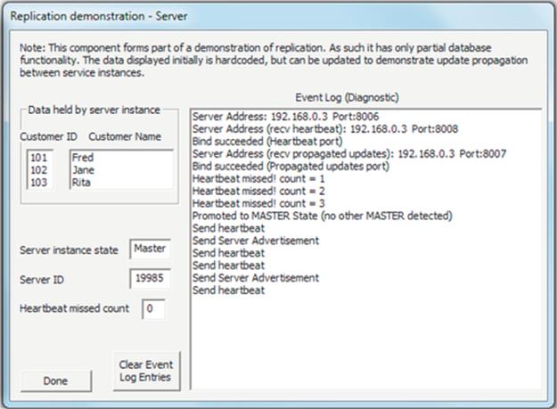
The following screenshots show the client component waiting for the service advertisement message and then receiving it and updating the server address details it holds.
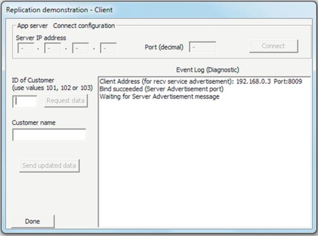
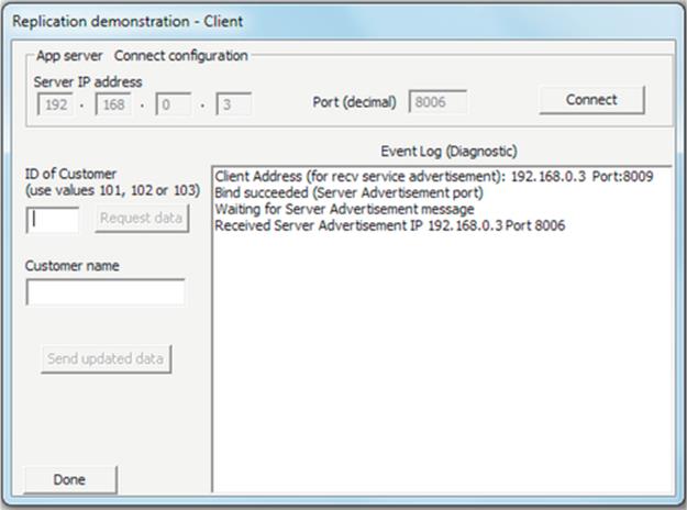
Method Part B: Using the Database Service
The application can now be used. Experiment with connecting the client to the server and requesting data items from the server. Data values held at the server can also be updated; try a few requests and a few updates.
Expected Outcome for Part B
The client should connect to the server (it establishes a TCP connection). You should be able to perform data requests and updates at the client and see the effect of these at the server.
The screenshot below shows the server state after the client has connected, and the customer number 101 name has been changed by the client from “Fred” to “Frederick.”
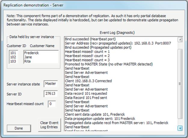
The screenshot below shows the corresponding state of the client interface after the data value was updated and sent to the server.
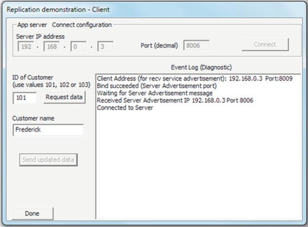
Method Part C: Component Self-Configuration (Two Servers)
This stage explores the self-configuration that occurs when there are two server instances present.
Start two instances of the service on different computers. One process should promote itself to master status (the same event sequence as explored in part A); the second instance then detects the heartbeat messages from the master process, causing it to remain in the backup state.
Expected Outcome for Part C
You should see that, by using the heartbeat mechanism, the service autoconfigures itself so that there is one master instance and one backup instance.
This screenshot shows the service instance that elevates to master. Typically, it is the one that is started first, because each instance waits the same time period to detect heartbeat messages, and the first one to start waiting is the first one to get to the end of the waiting period and elevate.
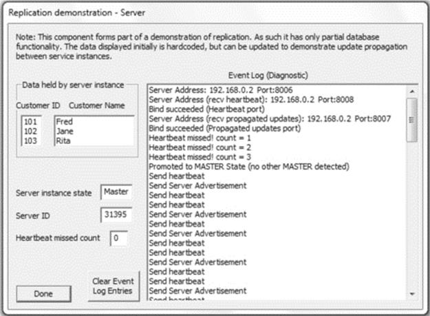
This screenshot (below) shows the server instance that remains in backup state because it is receiving the heartbeat messages from the master instance.
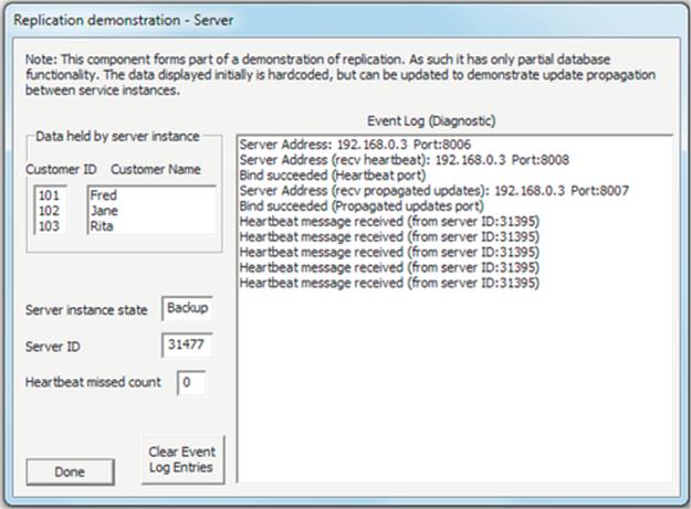
Method Part D: Update Propagation in Operation
Start two instances of the service on different computers (or continue on from part C).
Start a client on the same computer as one of the server instances, or use a third computer. The client will receive service advertisement messages from the master instance, and therefore, always connect to master; confirm this experimentally.
Notice that the customer with ID 102 initially has the name “Jane.” Use the client to change this to “John” (request the data, then manually edit the data in the client user interface, and then use the “Send updated data” button to send the new value back to the master server instance).
Expected Outcome for Part D
You should see that the update is performed successfully by the client, using the request-change-send sequence described above. The client interface is shown in the following screenshot.
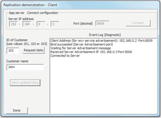
The master server instance receives the update request message from the client, performs the update on its own copy of the data, and also propagates the update to the backup server instance (as shown in the screenshot below) to maintain data consistency.
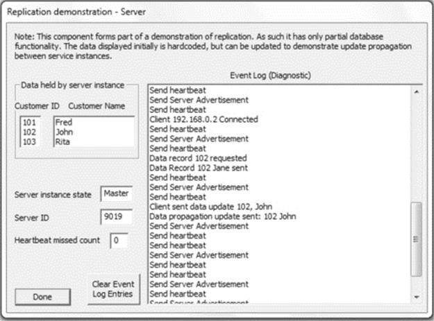
The backup server instance receives the propagated update from the master instance and updates its copy of the data accordingly; see the screenshot below.
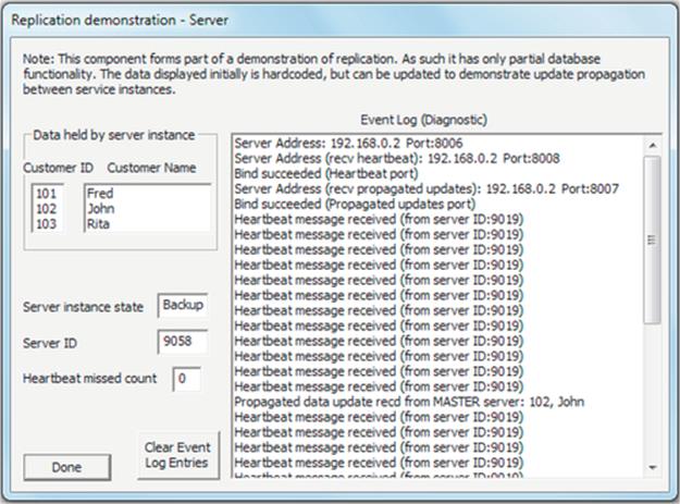
Method Part E: Automatic Reconfiguration and Failure Transparency
This stage explores the behavior when the master instance fails, and the backup server detects the lack of heartbeat messages.
Start one instance of the service on each of two different computers. Watch while the service self-organizes (i.e., one of the servers becomes the master instance, and the other remains in backup state).
Now, close the master instance (simulating a crash). Observe the behavior of the backup instance. It should detect that the master is no longer present (there are no heartbeat messages) and thus promote itself to master status.
Once the new master has established itself, restart the other server (which was originally the master). Upon starting up, it should detect the heartbeat messages being sent by the current master instance, and thus, the restarted server should remain in the backup state.
Expected Outcome for Part E
The screenshot below shows the backup service instance detecting the absence of the master: when three consecutive heartbeats have been missed, it promotes itself to master status and begins to broadcast heartbeat messages and server advertisements.
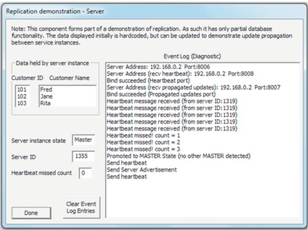
When the other instance of the service (which was previously the master and then crashed) is restarted, it detects the heartbeat messages from the current master and thus assumes backup status, as shown in the screenshot below. Note the new server ID of the restarted instance (1884), instead of its original ID (1319) when it was running previously (evidenced in the screenshot above when it was sending heartbeat messages). This is because the ID is randomly generated when the server process starts. Note also the ID of the other (now master) instance remains unchanged (1355).
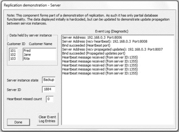
Reflection
This activity facilitates exploration of data replication in a realistic application setting. Through practical experimentation, you can see how several important mechanisms operate (service advertisement, heartbeat messages, and data update propagation). These are used to achieve automatic component discovery and service self-configuration, as well as the higher-level achievement of active data replication to achieve a robust, failure transparent database service.
It is recommended that you experiment further with the replication demonstration application to gain an in-depth understanding of its various behaviors. You should also inspect the source code and try to marry up the behavior witnessed to the underlying program logic.
5.17 The Relationship Between Distributed Applications and Networks
Distributed systems add management, structure, and most significantly transparency on top of the functionality provided by the underlying networks to achieve their connectivity and communication. Therefore, distributed applications should be considered as being in a layer conceptually above the top of the network protocol stack and not as part of the application layer.
To put this into context, consider the File Transfer Protocol (FTP). This commonly used application-layer protocol can be realized in an application form, that is, a file transfer utility, and also can be embedded into applications that may integrate a file transfer function within their general operation (such as system configuration and management utilities and automated software installers). See Figure 5.43.
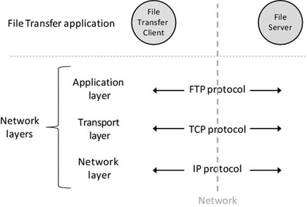
FIGURE 5.43 Distributed applications sit above the application layer.
Figure 5.43 shows the distinction between FTP, which is part of the network protocol stack, and a file transfer application. A file transfer application wraps the FTP functionality within an application form; it is software built on top of the FTP protocol and possibly integrates the functionality of transferring files with other functionality such as security and a bespoke user interface suitable for the intended use scenario. In the case of a file transfer utility, the client component is fundamentally a user interface enabling the user to submit commands to the server. The business logic is contained within the server component. The user must identify the file server by address when connecting, so this application provides limited transparency, and as such, it could be described as a network application rather than a distributed application.
Distributed applications use the connectivity provided by the network protocols as building blocks to achieve more sophisticated communication scenarios, especially by incorporating services and mechanisms such as name services and replication to achieve higher usability and especially transparency such that the user need not be aware of the distributed nature of the applications. For example, a file service that automatically mirrors changes in your local file system to a backup service in the cloud would have greater functionality than a file transfer utility and significantly would be far more transparent. See Figure 5.44.
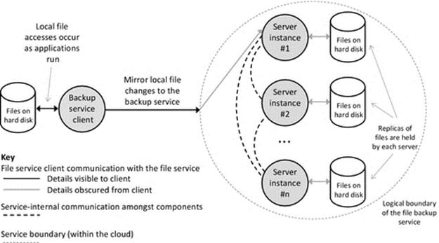
FIGURE 5.44 A file service as an example of a distributed application.
Figure 5.44 illustrates a distributed file service application. The extent of transparency provided enables the client to make service requests without being aware of the configuration of the service itself. The client does not need to know the actual number of server entities, their location, or the way they communicate within the service, achieve a logical structure, and maintain data consistency. So long as the client's service requests are met, then all is well from the client's point of view.
Network printing provides a further example for discussion. The print-client component can be embedded into, or invoked by, various applications from which the user may need to print a document (such as word processors and web browsers). The print server is a process that runs on the remote computer, which is connected to the printer, or the server may be embedded into the printer itself if it is a stand-alone network printer with its own network identity. The client performs the role of sending documents to the printer. This is essentially a file transfer, but with added control information, which includes the portion of the document to print, the print quality to use, and the number of copies required. The main business logic (such as checking access rights, queue management, and logging print jobs) and the actual printing are managed within the print server component. As with a file transfer utility, a network printing facility has limited transparency and thus could be described as a network application rather than a distributed application.
5.18 Transparency from the Architecture Viewpoint
The forms of transparency that are particularly important from the architecture viewpoint are briefly identified here and are treaded in more depth in Chapter 6.
Access transparency. The mechanisms to access resources should not be affected or modified by the software architecture of the application or by the type of coupling between components. The use of services to facilitate connectivity, such as name services and middleware, should not negatively impact access transparency.
Location transparency. Software architectures should be designed to support location transparency, especially where dynamic configuration and/or loose coupling is used. Location transparency should be maintained when components are relocated or when component roles change dynamically due to internal service reconfiguration.
Replication transparency. Replication of components is a key architectural technique to enhance robustness, availability, and responsiveness. This must be implemented such that the internal configuration and behavior within the replicated services (including details of server cardinality, server failures, and update propagation) are hidden from the external components that communicate with the services, such that they are presented with a single-instance view of the service.
Failure transparency. Failure transparency at the component level should be supported within the architectural design, using techniques such as loose coupling, dynamic configuration, and replication.
Scaling transparency. Software architectures should avoid unnecessarily complex or intense coupling between components. Tight coupling should be replaced with loose coupling using intermediate connectivity services where possible. The extent of interdependency and rigid structure between components impacts on maintainability and flexibility aspects of scalability.
Performance transparency. The intensity of communication between components should be considered carefully in the architectural design, because it can impact severely on performance. In general, the number of other components that each component communicates with should be kept to a minimum.
5.19 The Case Study from the Architectural Perspective
The game has a CS architecture. The game server has limited functional scope since it is intended primarily for demonstration and exploration; it only provides the business logic for a simple game, as well as the management of a list of up to ten connected users and a list of up to five simultaneously active games. The CS design is well suited to the game in its current form, simplicity being its main advantage in this case. There are only two-component types; the client provides the user interface and the server provides the business logic. At the small scale of this application, there are no issues with performance.
If the application were to be extended to support features such as user registration and authentication or multiple different games or if it needed to be scaled up to support large numbers of users, then a three-tier design may be more suitable because of its flexibility and better transparency provision.
5.19.1 Stateful Server Design
The game is based on a stateful server design; the server stores the game state including which players are associated by a particular game and which of the players has the next turn to make a move. The server sends messages to each client containing details of the moves made by the opponent so that both clients display an up-to-date representation of the game-board positions. When designing the game application, it was necessary to weigh up the relative advantages and disadvantages of the stateful and stateless approaches, in the specific context of the game. The stateful server approach is the more natural choice for this particular application because the server provides a connection between pairs of clients playing a game and needs access to the game state to mediate between the clients in terms of controlling the game action; if the server did not store the state locally, then the messages passed through the server between the clients would need to additionally contain the state information. The negative aspect of stateful design in this case is that if the server were to crash, the game will be destroyed.
The stateless server alternative requires spreading the state across the two clients such that they each hold details of their own and their opponent's move positions. This approach would increase the complexity of both the client and the server components. The client becomes more complex as it has to manage the state locally, and the server becomes more complex because it is much harder to govern the game, in terms of preventing clients from making multiple moves at one turn, not taking a turn, or reversing previous moves. This is because the server would only see snapshots of the game from step to step, instead of following it/enforcing it on an alternating move-by-move basis, which it controls (as in the case of the stateful design). In addition, the stateless server approach causes there to be separate copies of the state at each client, and therefore, it is possible for inconsistency to arise through the two sets of state becoming out of sync, such as if both clients think it is their turn to move at the same time (in which case the game is effectively destroyed anyway). The additional design and testing that would be required to ensure the game state remains consistent in all scenarios that could occur would far outweigh the single negative aspect of the stateful design in this case, and bear in mind that the stateless server approach is still sensitive to the failure of either client.4
5.19.2 Separation of Concerns for the Game Components
The game comprises two-component types with clearly defined roles. The server keeps the application state organized in a two-level hierarchy. The lower level holds information concerning the connected clients (representing players), which is held within an array of connection structures (one structure per client). The higher level relates players to games in play using an array of game structures (one structure per game). The game structure also holds the game-grid state, which is updated as the server receives gameplay move messages from each client and forwards them to the client's opponent. A logical game is created when one player selects another from the “available players” list, which is updated and transmitted to each connected client when a new client joins, leaves, or becomes tied up in a game. The demonstration application supports up to five simultaneous games, by holding an array of five game structures. The connection and game structures have been presented in Chapter 3.
5.19.2.1 CS Variant
The game is an example of the fat-server variant of the CS architecture, in which the client provides the user interface logic, while the server provides the game logic as well as the data and state management. In this case, the processing demands on the server, per game (and thus per client), are quite low. The message arrival frequency is low, with game move messages arriving at typical intervals of at least two seconds or so, per game.
5.19.2.2 Client and Server Lifetimes
As with most CS applications, the game has been designed such that the client is the active component that connects to the server on demand of the user (i.e., when the user wishes to play a game, they will run the client process). To support on-demand connectivity, the server is required to run continuously, whereas the client has a short lifetime (the duration of a game session). The individual client lifetimes are independent of those of other clients, but of course, a client can only be linked in a game with another client that is present at the time of game initiation. To ensure meaningful game management, and to avoid wasting system resources, one of the roles of the server is to detect the loss of connection with one of the client processes and to close the game.
5.19.3 Physical and Logical Architectures of the Game Application
Physical architecture is concerned with the relative distribution of components, the specific location of each and the way in which they are connected and communicate. In contrast, logical architecture is concerned with the identity of components and the communication mappings between components without knowledge of actual physical system configuration. This difference gives rise to two different architectural views of the game.
Figure 5.45 shows the physical view of the game application when a game between two users is in play. The two users (players) each have a computer on which they run the game client program (which causes an instance of the game client process to run on each computer). The game server program is running on a third computer (the running instance of this program is the server process). The computers are connected via the physical network and communicate using the IP protocol at the network layer. The processes communicate the game-application messages at the transport layer and thus could use either the TCP or the UDP protocols, each of which is encapsulated and carried across the network by the IP protocol. TCP was chosen for the game due to its reliability. The processes are identified for the purposes of the TCP communication by a combination of their host computer's IP address and the port number they are using, because this is the way in which the sockets (the communication end points) are differentiated. Figure 5.46provides a logical view of this situation.
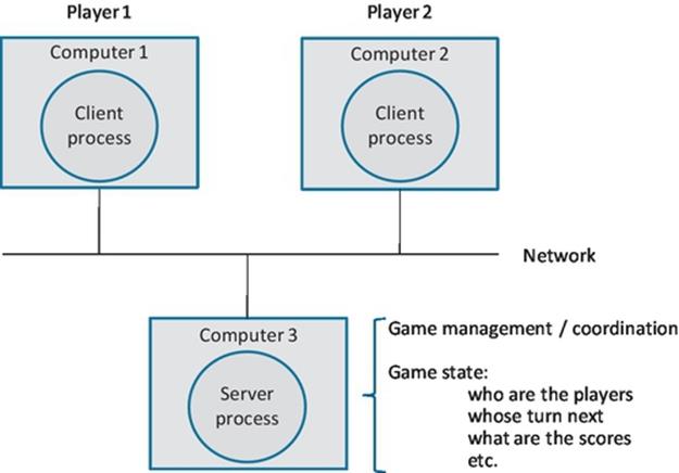
FIGURE 5.45 The physical architecture of the game.
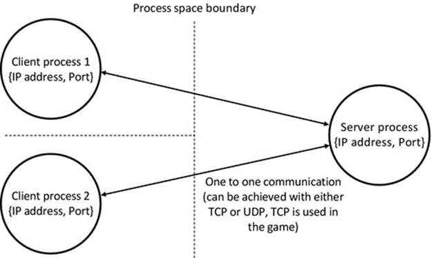
FIGURE 5.46 Logical view of the game connectivity.
Figure 5.46 shows the logical view of the physical system that was shown in Figure 5.45. This can be mapped onto the transport layer of the network model, in which the communicating processes are identified by the ports they are mapped to. The separation between the processes is indicated by the dotted lines; this indicates that the processes are independent entities in the system. This could, but does not have to, designate the presence of the physical network. In other words, the logical view is only concerned with which processes communicate with which other processes and is not concerned with the actual locations of processes. The communication used in the game has been configured such that processes can be located on the same or different computers because only the server process binds to the port that is used. At the transport layer, the network can be abstracted as a logical concept (because it facilitates process-to-process connectivity without concern for details of how it is achieved, such as which technologies are used or how many routers there are in the path). Both the TCP and the UDP transport layer protocols will deliver messages from process to process in an access transparent manner (this means that the mechanism to perform the send and receive actions is identical regardless of whether the two processes are on the same computer or different computers). See also the discussion of logical and physical views of systems in Chapter 3.
Server replication can be used to increase the robustness of an application such as the game, and it can also improve scalability and availability in large systems. However, replication also increases complexity, especially if state has to be propagated between the server instances. The example game does not need to scale up to large numbers of players and the service provided is not considered sufficiently important to justify the additional design, build, and test expense of adding server replication. However, if the game were to be part of an online casino, with paying customers expecting a highly robust and available service, then the decision would be different.
5.19.4 Transparency Aspects of the Game
Ideally, users of distributed applications are provided with an abstraction, which hides the presence of the network and the boundaries between physical computers such that the user is presented with a single-machine view of the system. Obviously, in a multiplayer game, the user is aware that there is at least one other user who is located at a different computer and that they are connected by a network; this is an example where full network transparency is not necessary or achievable. However, the user does not need to know any of the details concerning the connectivity, distribution, or internal architecture of the game application.
Locating the server: In the case study game, the user manually enters the IP address of the server. This is an issue from a transparency point of view because it reveals the distributed nature of the game and also requires the user to know, or find out, the address of the server. Techniques to automatically locate the server, such as the server advertisement used in the replication demonstration earlier in the chapter, could be used. Adding server advertisement to the use-case game is one of the programming challenges at the end of Chapter 3.
5.20 End-of-Chapter Exercises
5.20.1 Questions
Q1. Design-specific transparency implications. This question refers to the Activity A1, specifically the three-tier single application server configuration (configuration C).
A single data request message is sent by the client to the single application server. The application server uses the content of this message to create a pair of request messages, one for each specific database. Responses to these messages are returned from the two databases to the application server and are forwarded on by the application server as two separate responses to the client.
(a) Explain the transparency implications of this design decision.
(b) What would be the consequences of combining the two responses (one from each database) into a single reply to the client?
Q2. Software architectures. Identify the main benefits and drawbacks of the following architectures:
(a) Client-server
(b) Peer-to-peer
(c) Three-tier
(d) Multitier
(e) Distributed objects
Q3. Component coupling. Identify the type(s) of coupling occurring in each of the following scenarios:
(a) A CS application operating over middleware
(b) A prototype three-tier system that uses hard-coded addresses to identify the locations of components
(c) A multitier application in which components use a directory service to find the addresses of other components
(d) A peer-to-peer application in which components connect to one another when discovered in the local network (the discovery process is automatic, based on the use of broadcast messages)
(e) A social-media application in which clients connect to an online service to exchange information
(f) A CS application that uses server advertising broadcasts to enable the client to locate the server and establish a connection.
Q4. Identifying heterogeneity. Identify the classes of heterogeneity that may occur in each of the following scenarios:
(a) A computer laboratory with computers purchased in batches over a two-year period, installed with the Windows operating system and the same suite of application software on all computers.
(b) A small company network system comprising a couple of different desktop computers running various versions of the Windows operating system and a couple of laptops also running the Windows operating system.
(c) A system that supports a CS business application. A powerful computer running the Linux operating system is used to host the server process. Users access the service through lower-cost desktop computers running the Windows operating system.
(d) An ad hoc network created between a group of friends playing a multiplayer game over wireless links on a collection of mobile devices including smartphones and tablets.
(e) A home network system comprising a desktop computer running the Linux operating system and a laptop running the Windows operating system and a laptop running the Mac OS X operating system.
5.20.2 Programming Exercises
Programming Exercise #A1: This programming challenge relates to the demonstration distributed database application used in Activity A1. Base your solution on configuration C of the database application architecture (see the details in the activity).
Implement autoconfiguration so that the application server component can detect and automatically connect to the database servers. The recommended way to achieve this is for a service advertisement mechanism to be added to the database servers (see the replication demonstration application source code for an example mechanism).
Programming Exercise #A2: This programming challenge relates to the demonstration distributed database application used in Activity A1. Base your solution on configuration C of the database application architecture (see the details in the activity).
Implement autoconfiguration so that the application client component can detect and automatically connect to the application server. The recommended way to achieve this is for a service advertisement mechanism to be added to the application server (see the replication demonstration application source code for an example mechanism).
Programming Exercise #A3: This programming challenge relates to the demonstration peer-to-peer application used in Activity A2. The peer-to-peer media-sharing application automatically discovers peers and displays the additional resources they have. This allows the user to play soundtracks regardless of which peer holds them. However, the demonstration application does not detect peer disconnection, so the actual music track availability list could be stale. This programming task is to extend the functionality of the peer-to-peer application to correct this situation.
Starting with the provided project and source code (for the application used in Activity A2), add a simple heartbeat detection mechanism so that each peer can monitor the continuing presence of those other peers that it has already detected. Hint: the peers already generate periodic self-advertisement messages, but currently, a receiver ignores these from a particular sender once it has discovered that sender. Modification of the receive logic would allow these to be used to check that the peer is still present. If a peer is not detected for a certain period, then it is assumed to be no longer present and the local peer must stop advertising the resources that the lost peer held. In terms of how long to wait before determining that a peer has gone, perhaps, three missed self-advertisement messages in sequence are appropriate (as was done with the master presence detection in the replication demonstration; see Activity A3) although you can experiment with other configurations.
Implementation note: After being used in Activity A2, the peer-to-peer application was refactored and developed as a library version, in Section 5.13. Hence, there are three versions of the sample code available. You can use any of these versions of the peer-to-peer application as your starting point (the original version, the refactored version, or the library version, but note that the sample solution is based on the refactored version).
An example solution is provided in the program MediaShare_Peer_Disconnect.
Programming Exercise #A4: This programming challenge relates to the demonstration replicated database application used in Activity A3.
Implement a full-database transfer mechanism. The replicated database example application currently only supports incremental update propagation. What this means is that each update that happens at the master instance is propagated, on an individual basis, to the backup instance. This has the potential weakness that if the backup server was unavailable for some time (it has a crash or is shutdown) and then restarted, it may have missed several updates. This task requires you to develop a mechanism whereby the backup server instance (upon start-up) requests a full-database transfer from the master server instance. You will need to add a new message type REQUEST_FULL_DATABASE_TRANSFER to enable the backup instance to make the request. You may be able to use the existing update propagation mechanism (but within a loop) to transfer the database rows one by one.
An example solution is provided in the program Replication_Server_DB_Transfer.
5.20.3 Answers to end-of-Chapter Questions
Q1. Answer
(a) The transparency implications of the design include the following:
• Sending back two replies, arising as the result of a single query sent by the client, requires the client logic to be able to receive and process the messages without confusion.
• The approach reveals clues as to the internal architecture of the service, specifically in this case that there are multiple database servers (breaking the single-system view).
• In the specific way it has been implemented, this approach is robust and to some extent provides failure transparency in the sense that it allows the client to receive data from one database when the other is unavailable.
• The approach is not universally suitable, since in many database applications, it is not desirable to receive incomplete responses from queries.
(b) The consequences of combining the two responses (one from each database) into a single reply to the client include the following:
• Additional complexity in the application server. The two replies from the database servers arrive asynchronously at the application server, so there would need to be a means of waiting until both responses were available before passing a single reply message back to the client.
• The timing aspects could be difficult, specifically how long should the application server wait for the pair of responses. If it waits indefinitely, the service will be unreliable in the event that one of the database servers has crashed. If it waits too long before timing out, then the service will be robust but with higher than necessary latency. If it does not wait long enough before timing out, then valid responses from databases will be lost.
Q2. Answer
(a) CS is a very popular architecture for distributed systems and is well understood. This two-tier approach works well at low scales or with limited complexity applications. The two types of component have different functionality and behavior; a key aspect that affects performance and scalability is the way in which the functionality is divided across the component types.
(b) Peer-to-peer applications have a single-component type. Many components can connect together, often on an ad hoc basis, to achieve application-level goals, which are often related to data or resource sharing. A main benefit is dynamic run-time configuration flexibility. Connectivity in peer-to-peer applications can become a performance bottleneck, which thus affects scalability.
(c) The three-tier architecture facilitates separation of the three stands of functionality (user interface, business logic, and data access logic) such that a middle tier can be dedicated to business logic. This is more flexible and potentially more scalable and robust than the two-tier CS architecture but is also more complex (in terms of structure and behavior, thus requiring greater design and testing effort).
(d) Multitier is an extension of three-tier; it facilitates multiple middle tiers so that the business logic can be subdivided. This not only extends the flexibility and scalability advantages of three-tier designs (compared, e.g., with two-tier) but also further increases the complexity.
(e) The distributed objects approach is a fine-grained technique by which the application's logic is distributed at the object level. This means that there can be a large number of relatively simple objects distributed across a system, each providing quite limited but clearly defined functionality. The main advantage is the flexibility it offers. However, there is potentially high complexity, and if poorly designed, there can be large numbers of component-component dependencies and high interaction intensity, which impacts on robustness. Distributed objects applications rely on supporting infrastructure such as middleware to facilitate object location and also communication between objects.
Q3. Answer
(a) CS applications are directly coupled (in the common case where the client identifies the server explicitly) and loosely coupled when middleware is a communication intermediary.
(b) The use of hard-coded addresses implies design time-decided connectivity. The components in adjacent tiers connect directly to each other; hence, in this case, the coupling is tight and direct. The nonadjacent tiers (the user interface and the data access tier) connect indirectly to each other, through the middle tier, which acts as an intermediary, so in this case, the coupling is tight and indirect.
(c) The adjacent components are directly coupled, and the nonadjacent components are indirectly coupled (as in the answer to part (b) above). The directory service introduces loose coupling in that the location of components can be found at run time.
(d) The ad hoc connectivity is a form of loose coupling (the communication partners were not decided at design time). The components connect directly to each other, so the coupling is also direct.
(e) Clients connect indirectly (via the online service) and to any other clients (not known at design time) so the coupling between clients is indirect and loose. The connection between a specific client and the service itself is direct and tight (it was decided at design time).
(f) The use of a service advertisement mechanism implies loose coupling. The resulting connection is directly between a client and a server and thus is an example of direct coupling.
Refer to Section 5.5.1 for further explanation.
Q4. Answer
(a) It is possible that there is no heterogeneity present in this case. However, purchasing different batches of computers over an extended time period is likely to lead to resource differences, for example, the later batches may have larger memory, larger hard disk storage, or different variants of the CPU. Thus, it is likely that there is some performance heterogeneity present. In addition, it is possible that different versions of the Windows operating system are in use, potentially giving rise to operating system heterogeneity.
(b) The hardware platforms are likely to be compatible (the laptops should provide the same hardware interface as the PC), and thus, the platforms may offer the same interfaces to the processes and operating systems. It is likely that the platforms offer different levels of resource, so the system will exhibit performance heterogeneity. Operating system heterogeneity may arise if different versions of the Windows operating system are in use.
(c) Performance heterogeneity has been introduced purposefully to ensure the server process has sufficient resource to achieve the appropriate performance. Operating system heterogeneity is also present.
(d) This system exhibits all three forms of heterogeneity (performance, platform, and operating system). Different executable versions of the game will be needed for the various different devices, and the interoperability between the devices is achieved by using a standard communication mechanism.
(e) This system may exhibit all three forms of heterogeneity, although it is possible that the three platforms are compatible. Performance heterogeneity and operating system heterogeneity will be present, and in general, the different computers will be used for executing different applications (or components thereof).
5.20.4 List of in-Text Activities
|
Activity number |
Section |
Description |
|
A1 |
5.8 |
Exploring architecture, coupling, connectivity, and transparency with two-tier and three-tier versions of a database application |
|
A2 |
5.9.3 |
Exploring peer-to-peer architecture and behavior, using a peer-to-peer music-sharing application with ad hoc automatic configuration |
|
A3 |
5.16.3 |
Exploring replication, using a master-backup database application with service advertisement, heartbeat-based dynamic configuration of component roles, and update propagation among service instances |
5.20.5 List of Accompanying Resources
The following resources are referred to directly in the chapter text, the in-text activities, and/or the end of chapter exercises.
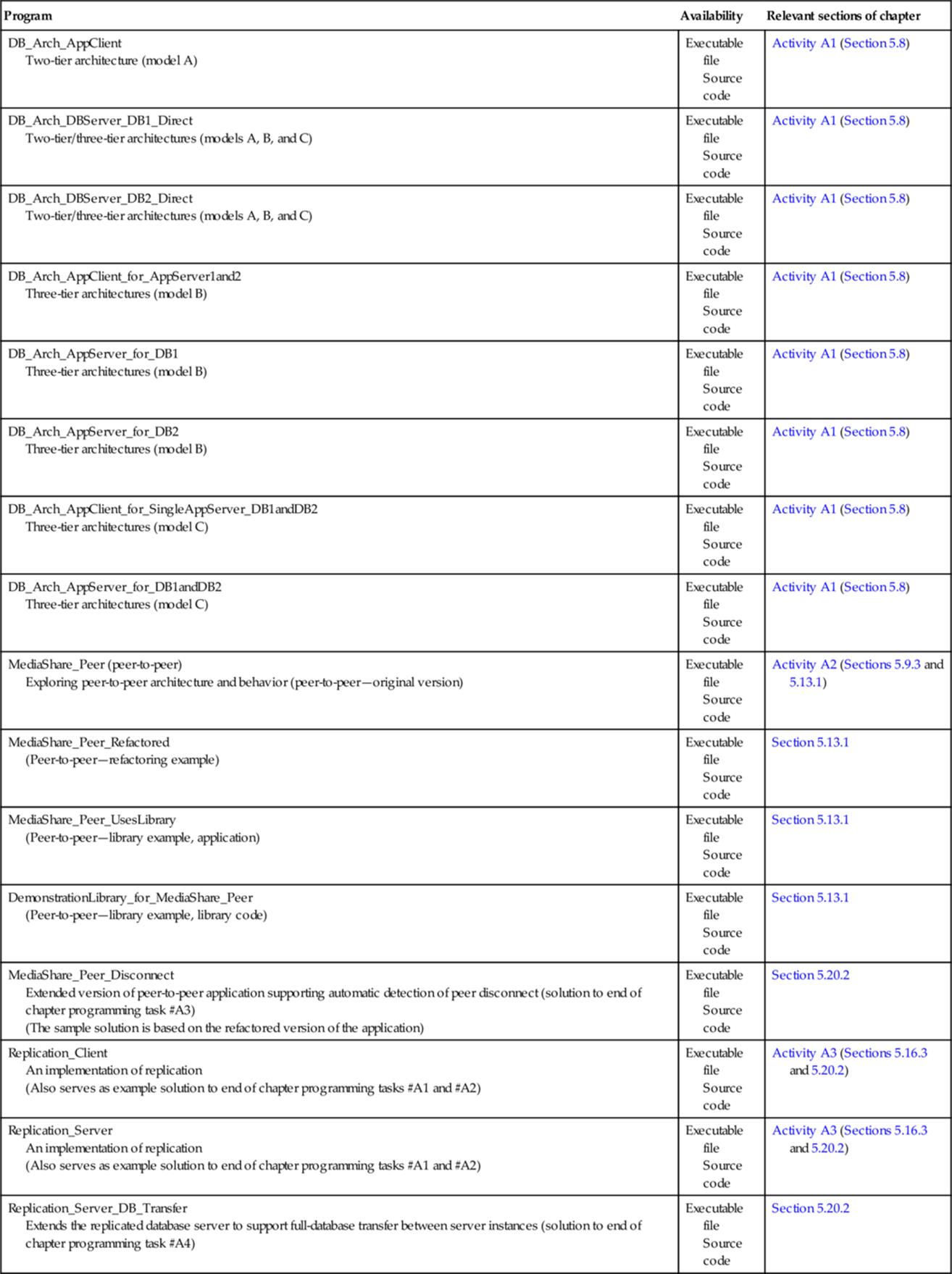
Appendix The Peer-to-Peer Application-Level Protocol Message Sequence
Activity A2 part C sets the challenge of determining the application-level protocol message sequence of the sample peer-to-peer application. The message sequence is shown in Figure 5.47 so that you can check your answers.
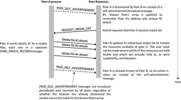
FIGURE 5.47 The peer-to-peer application-level protocol message sequence diagram.
1 A human behavior analogy of the changing of component's role is provided by the relationship between a salesperson in a shop and the customer. The salesperson (the server) serves the customer (who is the client). However, the salesperson may need to order some special goods for the customer, from another distributor. Thus, the salesperson's role changes to customer for the purposes of the second transaction when the salesperson requests goods from the external supplier.
2 The phrase “connections established in an ad hoc manner” essentially means that there will be various connections established between a particular peer and its neighbors, depending on perhaps the sequence with which specific peers joined the group (because some applications may limit the number of peers that an individual connects to), and the actual range between each pair of individuals (so different subsets are visible to each individual). Therefore, the exact mapping of connections might not be predictable and may be different even in similar (slightly different) situations.
3 Replication mechanisms provide a very good example of the general rule that whenever a new feature is added to an application or system, for whatever reason, it potentially introduces additional challenges or new failure modes. Circumventing the new challenges or protecting against these new failure modes can be costly in terms of design and development effort and especially testing (which must cover a wide state space of possible scenarios). Ultimately, we can find ourselves doing what the author terms “complexity tail chasing” in which we add increasing layers of complexity to deal with the issues arising from the complexity of earlier layers. Therefore, before adding any additional mechanisms such as replication, it is vital that a detailed requirements analysis has been carried out and that the consequences of adding the mechanism are considered and a balanced decision is made through in-depth understanding of the effective costs and benefits.
4 For this particular application (in which games are played between pairs of clients), a peer-to-peer design could also be considered and would have similar merits to the stateless server design, except that there would be no server, so there would need to be a mechanism to facilitate clients discovering and associating with one another to establish games. The peer-to-peer design would encounter the same challenges of duplication of game state and the need to ensure consistency as the stateless server approach does.