Real-Time Communication with WebRTC (2014)
Chapter 5. Putting It All Together: Your First WebRTC System from Scratch
We are finally ready to put all the pieces together and build our first WebRTC application. In this chapter, by leveraging a signaling server like the one we described in Chapter 4, we will implement the Browser RTC Trapezoid in a distributed scenario. Basically, we will take the running example of Chapter 3 and let it also work beyond the limits of a local perspective.
We will show how to use the signaling channel to allow two peers to exchange user media information, session descriptions, and ICE protocol candidates. We will also highlight how the signaling server role proves fundamental only during the setup phase. Indeed, once the above information has been successfully exchanged, the communication paradigm switches to pure peer-to-peer, with the server itself having no involvement in the actual data exchange phases.
A Complete WebRTC Call Flow
Figures 5-1, 5-2, and 5-3 provide the big picture associated with a complete WebRTC call flow involving a channel Initiator, a channel Joiner, and a signaling server relaying messages between them at channel setup time.
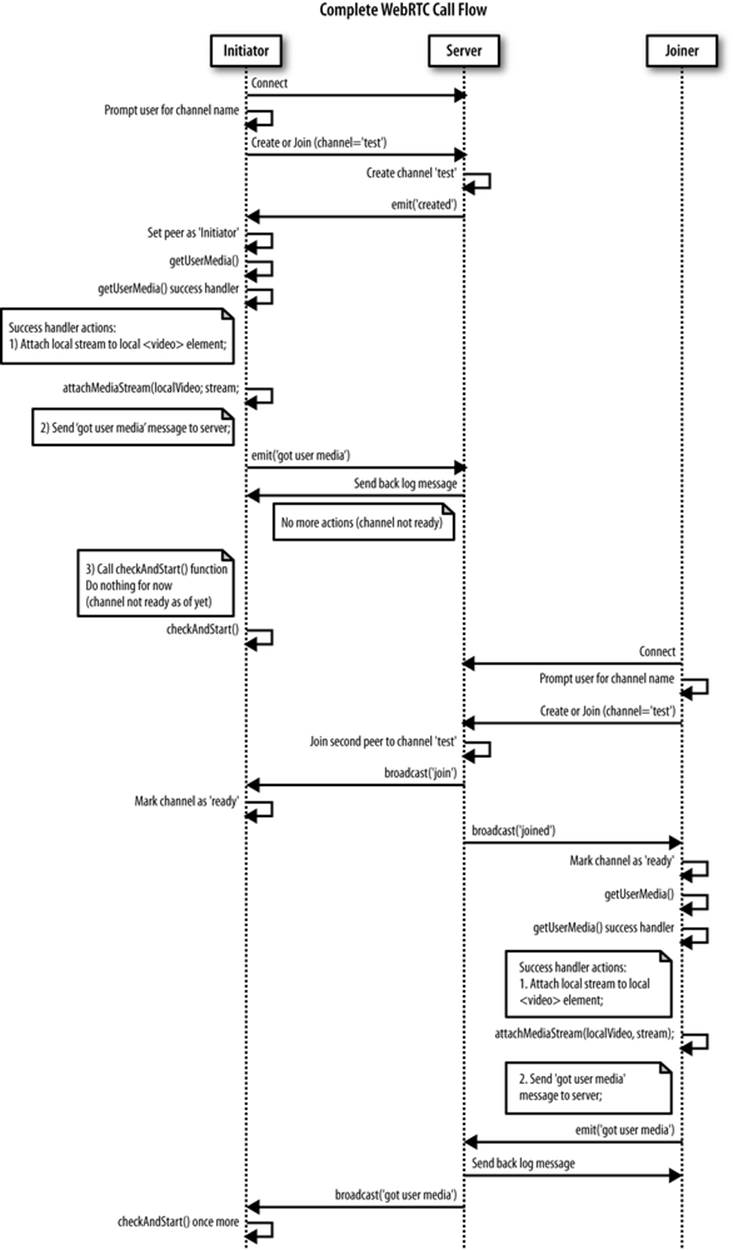
Figure 5-1. WebRTC call flow: Sequence diagram, part 1
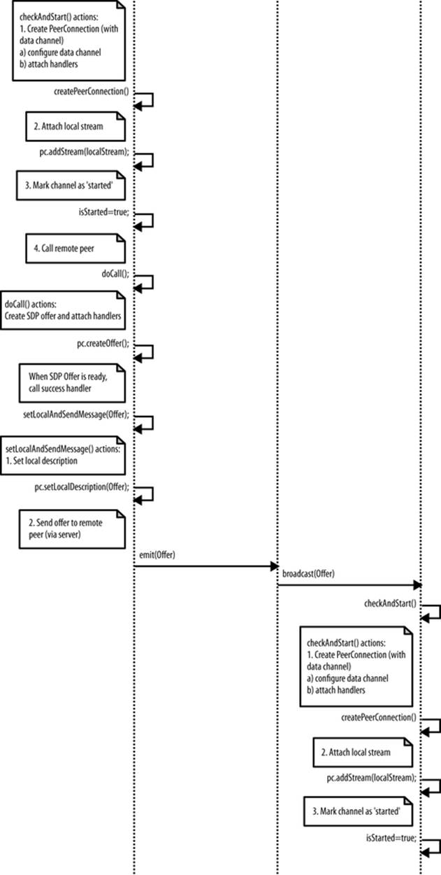
Figure 5-2. WebRTC call flow: Sequence diagram, part 2
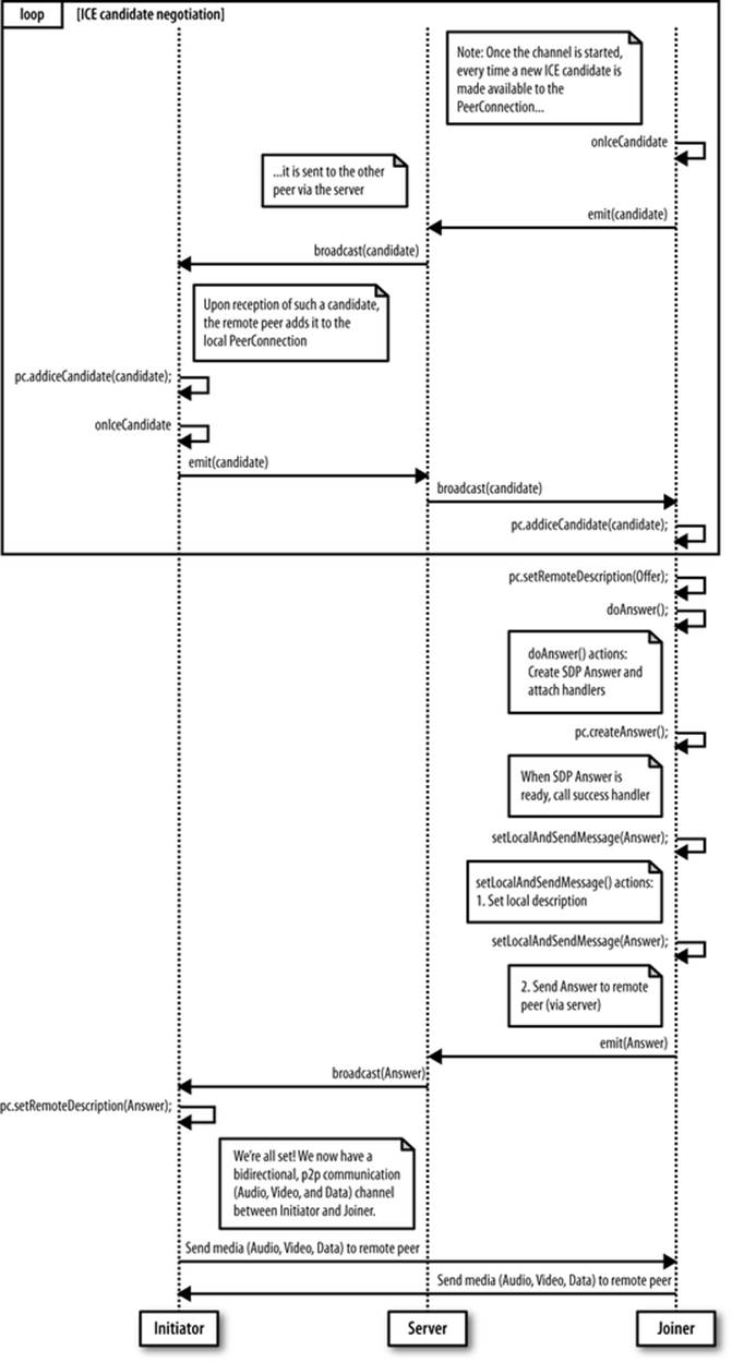
Figure 5-3. WebRTC call flow: Sequence diagram, part 3
The sequence diagram evolves through the following macrosteps:
1. The Initiator connects to the server and lets it create the signaling channel.
2. The Initiator (after getting the user’s consent) gets access to the user’s media.
3. The Joiner connects to the server and joins the channel.
4. When the Joiner also gets access to the local user’s media, a message is sent to the Initiator (through the server), triggering the negotiation procedure:
o The Initiator creates a PeerConnection, adds the local stream to it, creates an SDP offer, and sends it to the Joiner via the signaling server.
o Upon receipt of the SDP offer, the Joiner mirrors the behavior of the Initiator by creating a PeerConnection object, adding the local stream to it, and building an SDP answer to be sent back (via the server) to the remote party.
5. During negotiation, the two parties leverage the signaling server to exchange network reachability information (in the form of ICE protocol candidate addresses).
6. When the Initiator receives the Joiner’s answer to its own offer, the negotiation procedure is over: the two parties switch to peer-to-peer communication by exploiting their respective PeerConnection objects, which have also been equipped with a data channel that can be used to exchange text messages directly.
In the following sections, we will walk through these steps by analyzing each of them in further detail. Before doing so, let us introduce the simple web application we devised as a running example for this chapter; the HTML code is reported in Example 5-1.
Example 5-1. Simple WebRTC application
<!DOCTYPE html>
<html>
<head>
<title>Very simple WebRTC application with a Node.js signaling server</title>
</head>
<body>
<div id='mainDiv'>
<table border="1" width="100%">
<tr>
<th>
Local video
</th>
<th>
Remote video
</th>
</tr>
<tr>
<td>
<video id="localVideo" autoplay></video>
</td>
<td>
<video id="remoteVideo" autoplay></video>
</td>
</tr>
<tr>
<td class="center">
<textarea rows="4" cols="60"
id="dataChannelSend" disabled
placeholder="This will be enabled once
the data channel is up...">
</textarea>
</td>
<td class="center">
<textarea rows="4" cols="60"
id="dataChannelReceive" disabled>
</textarea>
</td>
</tr>
<tr>
<td class="center">
<button id="sendButton" disabled>Send</button>
</td>
<td></td>
</tr>
</table>
</div>
<script src='/socket.io/socket.io.js'></script>
<script src='js/lib/adapter.js'></script>
<script src='js/completeNodeClientWithDataChannel.js'></script>
</body>
</html>
Local video, as well as local data channel information, are shown on the left side of the page, whereas remote video and data are reproduced on the right side of the window. The page refers to three script files, the first of which is the already introduced socket.io library (see The socket.io JavaScript Library). As to the second file (adapter.js), it is a handy JavaScript shim library that helps the programmer by properly abstracting browser prefixes, as well as other browser differences and changes in the way vendors are currently interpreting the specs. Finally,completeNodeClientWithDataChannel.js contains the actual client code and is presented in Example 5-2 in its entirety for the benefit of the reader. We will dig into the details of this file in the remainder of this chapter.
Example 5-2. completeNodeClientWithDataChannel.js
'use strict';
// Look after different browser vendors' ways of calling the getUserMedia()
// API method:
// Opera --> getUserMedia
// Chrome --> webkitGetUserMedia
// Firefox --> mozGetUserMedia
navigator.getUserMedia = navigator.getUserMedia ||
navigator.webkitGetUserMedia || navigator.mozGetUserMedia;
// Clean-up function:
// collect garbage before unloading browser's window
window.onbeforeunload = function(e){
hangup();
}
// Data channel information
var sendChannel, receiveChannel;
var sendButton = document.getElementById("sendButton");
var sendTextarea = document.getElementById("dataChannelSend");
var receiveTextarea = document.getElementById("dataChannelReceive");
// HTML5 <video> elements
var localVideo = document.querySelector('#localVideo');
var remoteVideo = document.querySelector('#remoteVideo');
// Handler associated with Send button
sendButton.onclick = sendData;
// Flags...
var isChannelReady = false;
var isInitiator = false;
var isStarted = false;
// WebRTC data structures
// Streams
var localStream;
var remoteStream;
// PeerConnection
var pc;
// PeerConnection ICE protocol configuration (either Firefox or Chrome)
var pc_config = webrtcDetectedBrowser === 'firefox' ?
{'iceServers':[{'url':'stun:23.21.150.121'}]} : // IP address
{'iceServers': [{'url': 'stun:stun.l.google.com:19302'}]};
var pc_constraints = {
'optional': [
{'DtlsSrtpKeyAgreement': true}
]};
var sdpConstraints = {};
// Let's get started: prompt user for input (room name)
var room = prompt('Enter room name:');
// Connect to signaling server
var socket = io.connect("http://localhost:8181");
// Send 'Create or join' message to singnaling server
if (room !== '') {
console.log('Create or join room', room);
socket.emit('create or join', room);
}
// Set getUserMedia constraints
var constraints = {video: true, audio: true};
// From this point on, execution proceeds based on asynchronous events...
// getUserMedia() handlers...
function handleUserMedia(stream) {
localStream = stream;
attachMediaStream(localVideo, stream);
console.log('Adding local stream.');
sendMessage('got user media');
}
function handleUserMediaError(error){
console.log('navigator.getUserMedia error: ', error);
}
// Server-mediated message exchanging...
// 1. Server-->Client...
// Handle 'created' message coming back from server:
// this peer is the initiator
socket.on('created', function (room){
console.log('Created room ' + room);
isInitiator = true;
// Call getUserMedia()
navigator.getUserMedia(constraints, handleUserMedia, handleUserMediaError);
console.log('Getting user media with constraints', constraints);
checkAndStart();
});
// Handle 'full' message coming back from server:
// this peer arrived too late :-(
socket.on('full', function (room){
console.log('Room ' + room + ' is full');
});
// Handle 'join' message coming back from server:
// another peer is joining the channel
socket.on('join', function (room){
console.log('Another peer made a request to join room ' + room);
console.log('This peer is the initiator of room ' + room + '!');
isChannelReady = true;
});
// Handle 'joined' message coming back from server:
// this is the second peer joining the channel
socket.on('joined', function (room){
console.log('This peer has joined room ' + room);
isChannelReady = true;
// Call getUserMedia()
navigator.getUserMedia(constraints, handleUserMedia, handleUserMediaError);
console.log('Getting user media with constraints', constraints);
});
// Server-sent log message...
socket.on('log', function (array){
console.log.apply(console, array);
});
// Receive message from the other peer via the signaling server
socket.on('message', function (message){
console.log('Received message:', message);
if (message === 'got user media') {
checkAndStart();
} elseif (message.type === 'offer') {
if (!isInitiator && !isStarted) {
checkAndStart();
}
pc.setRemoteDescription(new RTCSessionDescription(message));
doAnswer();
} elseif (message.type === 'answer' && isStarted) {
pc.setRemoteDescription(new RTCSessionDescription(message));
} elseif (message.type === 'candidate' && isStarted) {
var candidate = new RTCIceCandidate({sdpMLineIndex:message.label,
candidate:message.candidate});
pc.addIceCandidate(candidate);
} elseif (message === 'bye' && isStarted) {
handleRemoteHangup();
}
});
// 2. Client-->Server
// Send message to the other peer via the signaling server
function sendMessage(message){
console.log('Sending message: ', message);
socket.emit('message', message);
}
// Channel negotiation trigger function
function checkAndStart() {
if (!isStarted && typeof localStream != 'undefined' && isChannelReady) {
createPeerConnection();
isStarted = true;
if (isInitiator) {
doCall();
}
}
}
// PeerConnection management...
function createPeerConnection() {
try {
pc = new RTCPeerConnection(pc_config, pc_constraints);
pc.addStream(localStream);
pc.onicecandidate = handleIceCandidate;
console.log('Created RTCPeerConnnection with:\n' +
' config: \'' + JSON.stringify(pc_config) + '\';\n' +
' constraints: \'' + JSON.stringify(pc_constraints) + '\'.');
} catch (e) {
console.log('Failed to create PeerConnection, exception: ' + e.message);
alert('Cannot create RTCPeerConnection object.');
return;
}
pc.onaddstream = handleRemoteStreamAdded;
pc.onremovestream = handleRemoteStreamRemoved;
if (isInitiator) {
try {
// Create a reliable data channel
sendChannel = pc.createDataChannel("sendDataChannel",
{reliable: true});
trace('Created send data channel');
} catch (e) {
alert('Failed to create data channel. ');
trace('createDataChannel() failed with exception: ' + e.message);
}
sendChannel.onopen = handleSendChannelStateChange;
sendChannel.onmessage = handleMessage;
sendChannel.onclose = handleSendChannelStateChange;
} else { // Joiner
pc.ondatachannel = gotReceiveChannel;
}
}
// Data channel management
function sendData() {
var data = sendTextarea.value;
if(isInitiator) sendChannel.send(data);
else receiveChannel.send(data);
trace('Sent data: ' + data);
}
// Handlers...
function gotReceiveChannel(event) {
trace('Receive Channel Callback');
receiveChannel = event.channel;
receiveChannel.onmessage = handleMessage;
receiveChannel.onopen = handleReceiveChannelStateChange;
receiveChannel.onclose = handleReceiveChannelStateChange;
}
function handleMessage(event) {
trace('Received message: ' + event.data);
receiveTextarea.value += event.data + '\n';
}
function handleSendChannelStateChange() {
var readyState = sendChannel.readyState;
trace('Send channel state is: ' + readyState);
// If channel ready, enable user's input
if (readyState == "open") {
dataChannelSend.disabled = false;
dataChannelSend.focus();
dataChannelSend.placeholder = "";
sendButton.disabled = false;
} else {
dataChannelSend.disabled = true;
sendButton.disabled = true;
}
}
function handleReceiveChannelStateChange() {
var readyState = receiveChannel.readyState;
trace('Receive channel state is: ' + readyState);
// If channel ready, enable user's input
if (readyState == "open") {
dataChannelSend.disabled = false;
dataChannelSend.focus();
dataChannelSend.placeholder = "";
sendButton.disabled = false;
} else {
dataChannelSend.disabled = true;
sendButton.disabled = true;
}
}
// ICE candidates management
function handleIceCandidate(event) {
console.log('handleIceCandidate event: ', event);
if (event.candidate) {
sendMessage({
type: 'candidate',
label: event.candidate.sdpMLineIndex,
id: event.candidate.sdpMid,
candidate: event.candidate.candidate});
} else {
console.log('End of candidates.');
}
}
// Create Offer
function doCall() {
console.log('Creating Offer...');
pc.createOffer(setLocalAndSendMessage, onSignalingError, sdpConstraints);
}
// Signaling error handler
function onSignalingError(error) {
console.log('Failed to create signaling message : ' + error.name);
}
// Create Answer
function doAnswer() {
console.log('Sending answer to peer.');
pc.createAnswer(setLocalAndSendMessage, onSignalingError, sdpConstraints);
}
// Success handler for both createOffer()
// and createAnswer()
function setLocalAndSendMessage(sessionDescription) {
pc.setLocalDescription(sessionDescription);
sendMessage(sessionDescription);
}
// Remote stream handlers...
function handleRemoteStreamAdded(event) {
console.log('Remote stream added.');
attachMediaStream(remoteVideo, event.stream);
console.log('Remote stream attached!!.');
remoteStream = event.stream;
}
function handleRemoteStreamRemoved(event) {
console.log('Remote stream removed. Event: ', event);
}
// Clean-up functions...
function hangup() {
console.log('Hanging up.');
stop();
sendMessage('bye');
}
function handleRemoteHangup() {
console.log('Session terminated.');
stop();
isInitiator = false;
}
function stop() {
isStarted = false;
if (sendChannel) sendChannel.close();
if (receiveChannel) receiveChannel.close();
if (pc) pc.close();
pc = null;
sendButton.disabled=true;
}
Based on the information contained in Chapter 4, the reader should face no issues in understanding the behavior of the signaling server, which has been written as a Node.js application and whose code is reproduced in the following:
varstatic = require('node-static');
var http = require('http');
// Create a node-static server instance
var file = new(static.Server)();
// We use the http module’s createServer function and
// rely on our instance of node-static to serve the files
var app = http.createServer(function (req, res) {
file.serve(req, res);
}).listen(8181);
// Use socket.io JavaScript library for real-time web applications
var io = require('socket.io').listen(app);
// Let's start managing connections...
io.sockets.on('connection', function (socket){
// Handle 'message' messages
socket.on('message', function (message) {
log('S --> got message: ', message);
// channel-only broadcast...
socket.broadcast.to(message.channel).emit('message', message);
});
// Handle 'create or join' messages
socket.on('create or join', function (room) {
var numClients = io.sockets.clients(room).length;
log('S --> Room ' + room + ' has ' + numClients + ' client(s)');
log('S --> Request to create or join room', room);
// First client joining...
if (numClients == 0){
socket.join(room);
socket.emit('created', room);
} elseif (numClients == 1) {
// Second client joining...
io.sockets.in(room).emit('join', room);
socket.join(room);
socket.emit('joined', room);
} else { // max two clients
socket.emit('full', room);
}
});
function log(){
var array = [">>> "];
for (var i = 0; i < arguments.length; i++) {
array.push(arguments[i]);
}
socket.emit('log', array);
}
});
Basically, the server looks after both channel management operations (creation upon reception of the Initiator’s request, join when the second peer arrives) and message relaying (at session setup time). As already anticipated, it completes its tasks right after a peer-to-peer session between the two browsers sharing the signaling channel has been successfully instantiated.
Let’s now get started with our complete WebRTC example walk-through.
Initiator Joining the Channel
Figure 5-4 shows the sequence of actions undertaken by the Initiator when the sample WebRTC application described in the previous section is started.
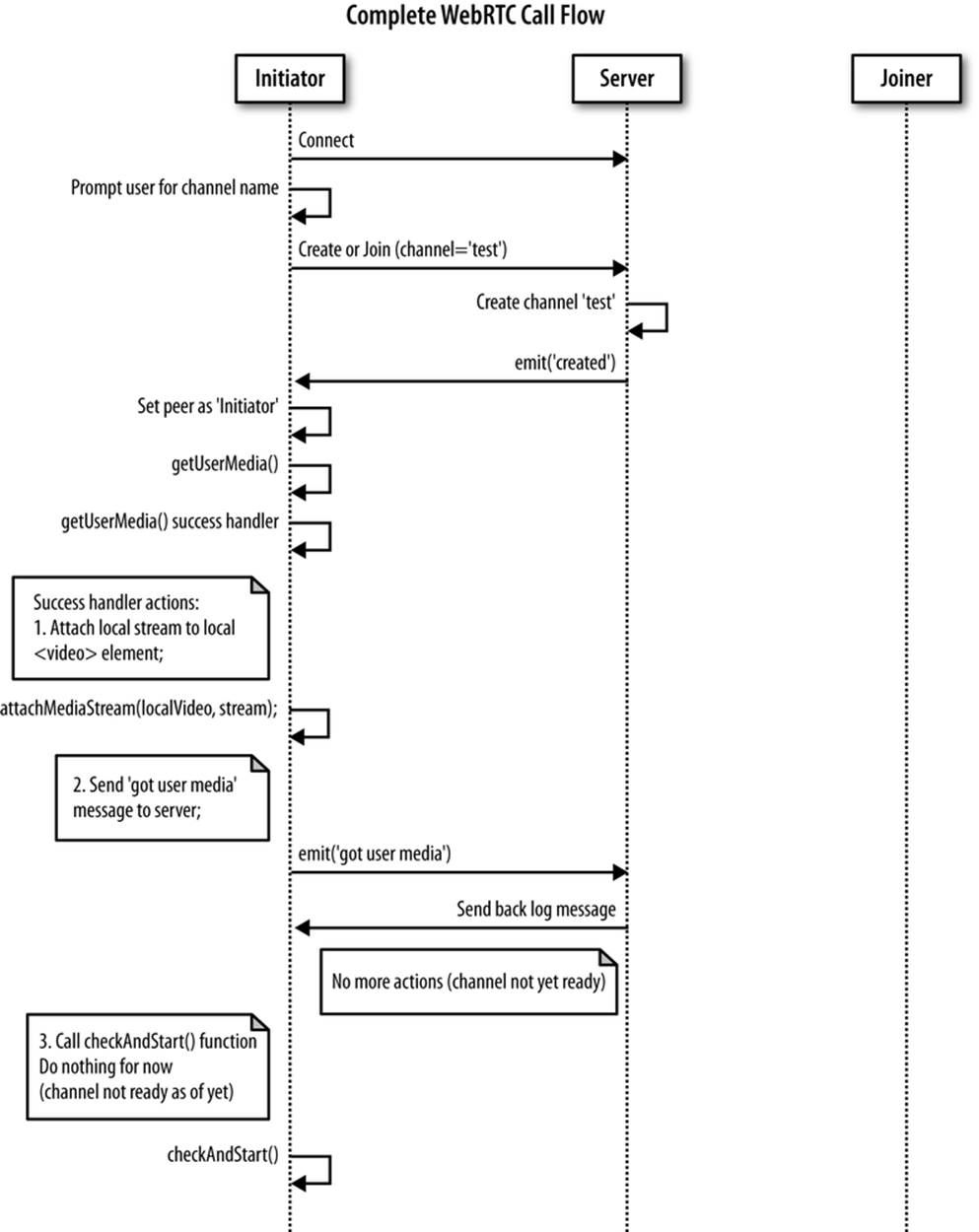
Figure 5-4. Initiator joining the channel
As shown in the figure, as soon as the web page is loaded in the browser, the user is first prompted for the channel name; then, the peer connects to the signaling server and sends it a create or join message. This is reported in the JavaScript snippet below and also shown in the snapshot inFigure 5-5:
...
// Let's get started: prompt user for input (room name)
var room = prompt('Enter room name:');
// Connect to signalling server
var socket = io.connect("http://localhost:8181");
// Send 'create' or 'join' message to singnalling server
if (room !== '') {
console.log('Create or join room', room);
socket.emit('create or join', room);
}
...
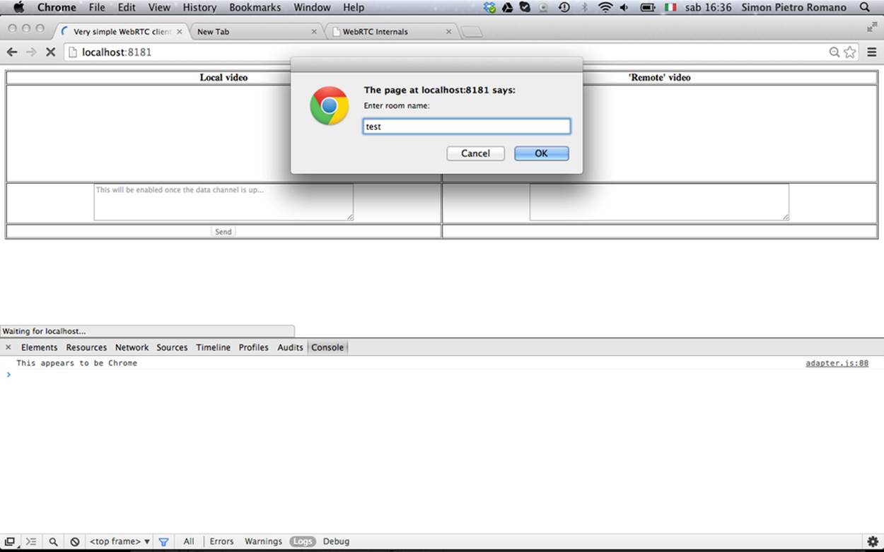
Figure 5-5. Initiator joining with Chrome browser
When the server receives the create or join message, it recognizes the peer as the Initiator and creates the server-side room associated with the required channel. It eventually sends a created message back to the client:
...
// Handle 'create or join' messages
socket.on('create or join', function (room) {
var numClients = io.sockets.clients(room).length;
log('S --> Room ' + room + ' has ' + numClients + ' client(s)');
log('S --> Request to create or join room', room);
// First client joining...
if (numClients == 0){
socket.join(room);
socket.emit('created', room);
} elseif (numClients == 1) {
...
...
Figure 5-6 shows the server’s console at this stage.
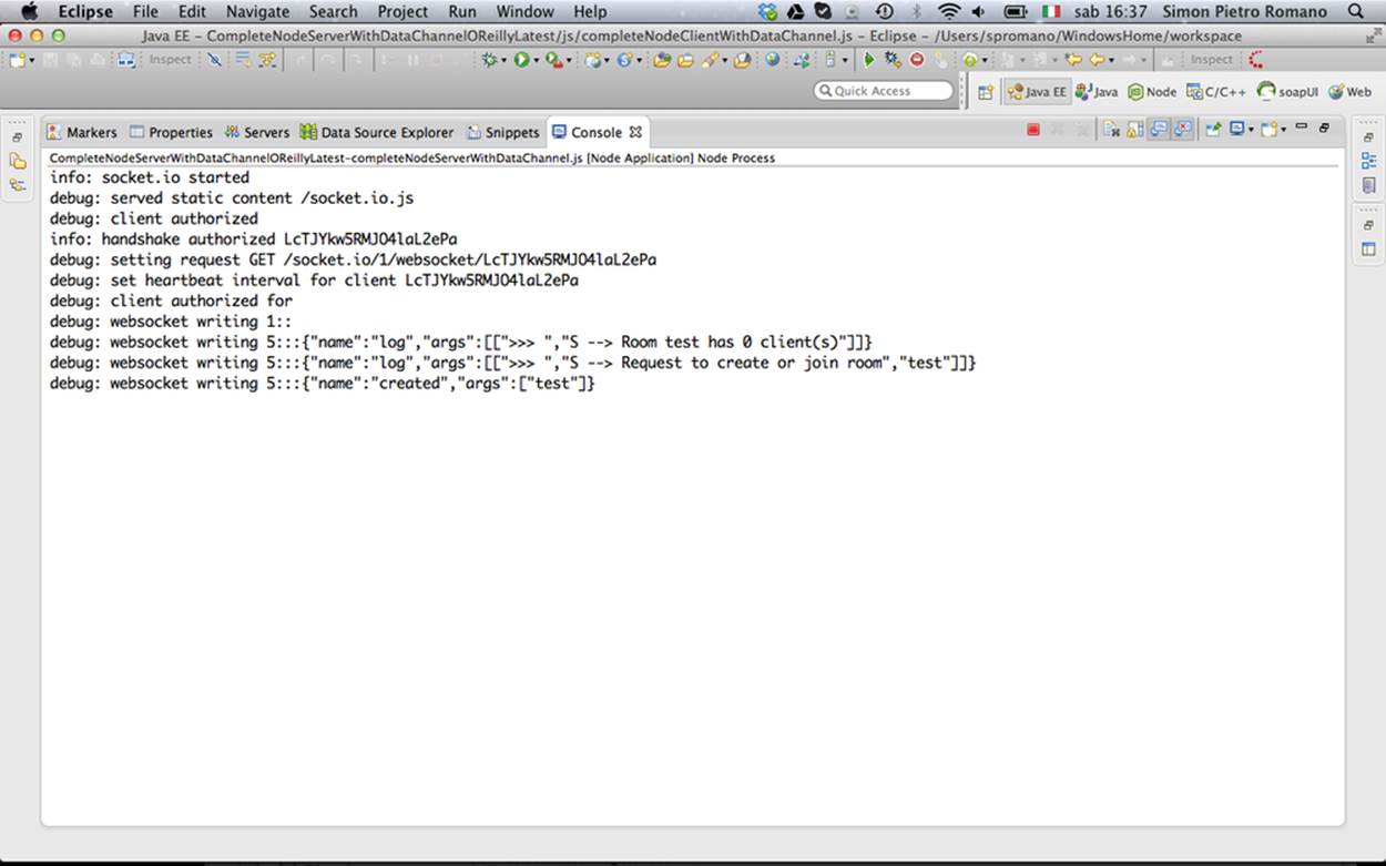
Figure 5-6. Signaling server creating the signaling channel
We have now reached the point where the client gets a created message back from the server and realizes it is going to play the role of the channel initiator:
// Handle 'created' message coming back from server:
// this peer is the initiator
socket.on('created', function (room){
console.log('Created room ' + room);
isInitiator = true;
...
The next action undertaken by the client is getting access to the user’s media through the getUserMedia() API call:
...
// Call getUserMedia()
navigator.getUserMedia(constraints, handleUserMedia, handleUserMediaError);
console.log('Getting user media with constraints', constraints);
...
Figure 5-7 shows the browser’s window right before getting the user’s consent.
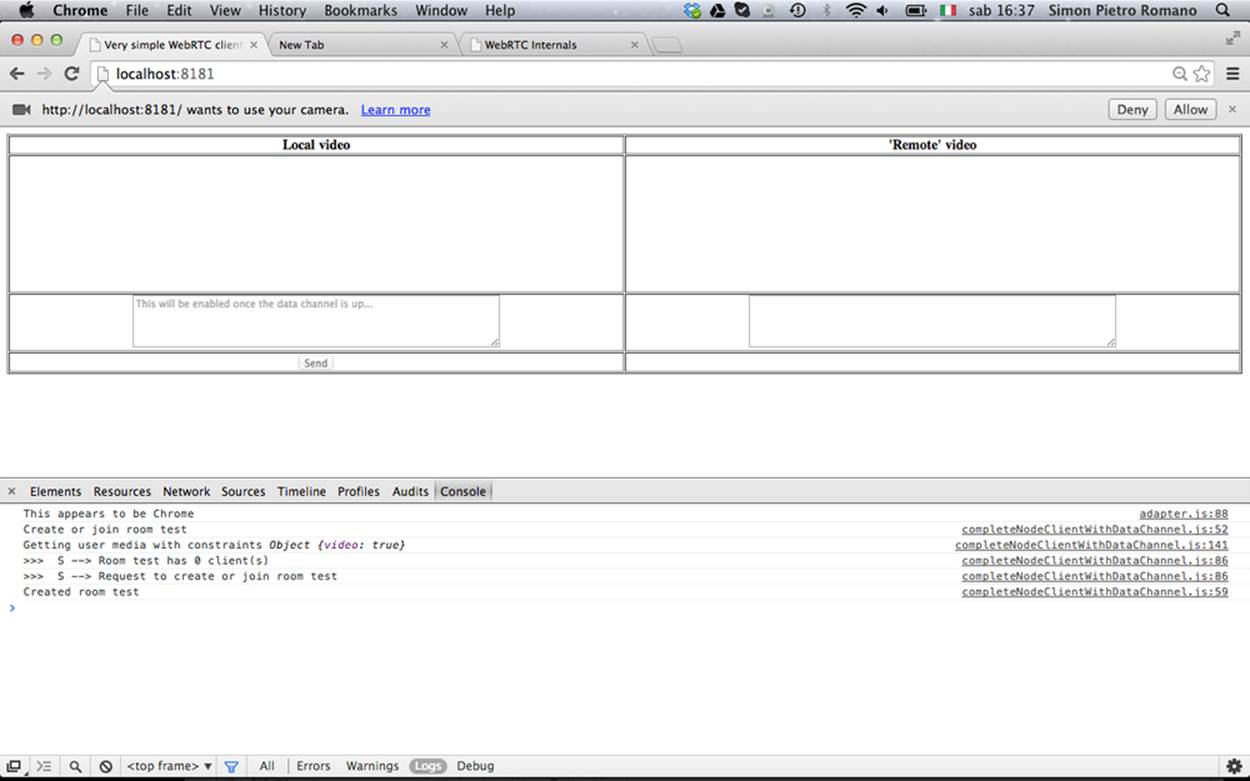
Figure 5-7. Initiator asking for user’s consent
The following snapshot reports the actions performed by the handleUserMedia() success handler: (1) the retrieved video stream is attached to the local <video> element of the HTML page; and (2) a got user media message is sent to the server.
...
function handleUserMedia(stream) {
localStream = stream;
attachMediaStream(localVideo, stream);
console.log('Adding local stream.');
sendMessage('got user media');
}
...
The effect of the first of these actions is shown in Figure 5-8.
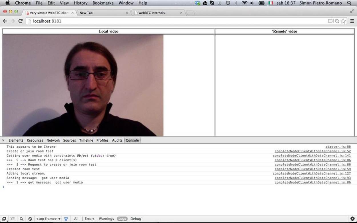
Figure 5-8. Initiator after user’s consent
The JavaScript code used to send messages to the server is given below:
...
// Send message to the other peer via the signaling server
function sendMessage(message){
console.log('Sending message: ', message);
socket.emit('message', message);
}
...
Server-side behavior associated with the reception of a generic message is shown in the following excerpt. The server first sends a logging message (which is also visible in the browser’s console in the lower part of Figure 5-8) back to the client and then broadcasts the received message to the remote party, if it exists (which is not the case at this point of the call flow):
...
// Handle 'message' messages
socket.on('message', function (message) {
log('S --> got message: ', message);
// channel-only broadcast...
socket.broadcast.to(message.channel).emit('message', message);
});
...
The last action performed by the channel initiator is the execution of the checkAndStart() function, which, at this stage of the overall call flow, actually does nothing, since the channel is not yet ready:
...
function checkAndStart() {
// Do nothing if channel not ready...
if (!isStarted && typeof localStream != 'undefined' && isChannelReady) {
...
...
Joiner Joining the Channel
Let’s now figure out what happens when the second peer joins the channel. The relevant sequence of actions is illustrated in Figure 5-9.
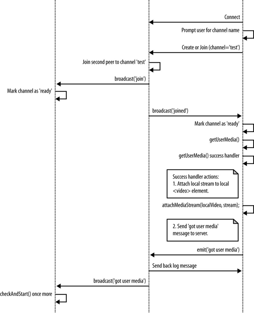
Figure 5-9. Joiner joining the channel
The first part of the diagram mirrors the behavior of the Initiator, prompting the user for a channel name and sending a create or join message to the server. Message handling on the server’s side (with the server’s console reported in Figure 5-10) this time envisages that a join message is sent to the Initiator (who can now mark the channel as ready), immediately followed by a joined response towards the Joiner:
...
} elseif (numClients == 1) {
// Second client joining...
io.sockets.in(room).emit('join', room);
socket.join(room);
socket.emit('joined', room);
} else { // max two clients
...
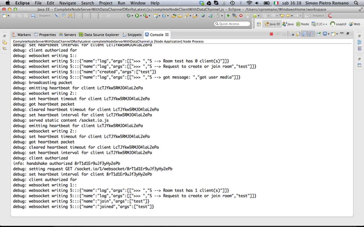
Figure 5-10. Signaling server managing Joiner’s request
The following excerpt shows the client-side actions associated with the reception of a join message:
...
// Handle 'join' message coming back from server:
// another peer is joining the channel
socket.on('join', function (room){
console.log('Another peer made a request to join room ' + room);
console.log('This peer is the initiator of room ' + room + '!');
isChannelReady = true;
});
...
Finally, the following JavaScript illustrates how the client realizes that it is playing the Joiner’s role since it gets back a joined response to the create or join request:
...
// Handle 'joined' message coming back from server:
// this is the second peer joining the channel
socket.on('joined', function (room){
console.log('This peer has joined room ' + room);
isChannelReady = true;
});
...
From this point on, the remaining actions performed by the Joiner at this stage of the negotiation are exactly the same as the ones we already described when looking at the Initiator’s role in the previous section: (1) access local media (waiting for the user’s consent); (2) attach local video to the HTML page; and (3) send a got user media message to the remote peer via the signaling server.
Initiator Starting Negotiation
Upon reception of the got user media message relayed by the server, the Initiator once again activates the checkAndStart() function, which is this time actually executed, since the boundary conditions have now changed: the channel is ready and the local stream has already been made available by the getUserMedia() API call.
The UML snapshot in Figure 5-11 and the following JavaScript code indicate that the Initiator (1) creates a PeerConnection object; (2) marks the channel as started; and (3) activates the doCall() JavaScript function.
...
// Channel negotiation trigger function
function checkAndStart() {
if (!isStarted && typeof localStream != 'undefined' && isChannelReady) {
createPeerConnection();
isStarted = true;
if (isInitiator) {
doCall();
}
}
}
...
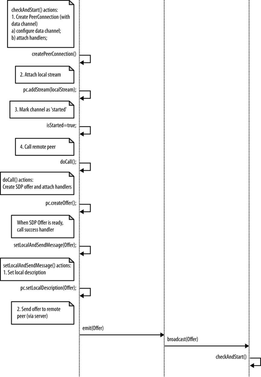
Figure 5-11. Initiator starting negotiation
Digging into the details of the above actions, the following code excerpt shows that a number of handlers are attached to the PeerConnection object in order to properly manage both ICE candidate addresses and remote stream addition and removal. Furthermore, the PeerConnection is also equipped with a data channel that will be used to exchange text data with the Joiner, in a peer-to-peer fashion:
...
function createPeerConnection() {
try {
pc = new RTCPeerConnection(pc_config, pc_constraints);
pc.addStream(localStream);
pc.onicecandidate = handleIceCandidate;
console.log('Created RTCPeerConnnection with:\n' +
' config: \'' + JSON.stringify(pc_config) + '\';\n' +
' constraints: \'' + JSON.stringify(pc_constraints) + '\'.');
} catch (e) {
console.log('Failed to create PeerConnection, exception: ' + e.message);
alert('Cannot create RTCPeerConnection object.');
return;
}
pc.onaddstream = handleRemoteStreamAdded;
pc.onremovestream = handleRemoteStreamRemoved;
if (isInitiator) {
try {
// Create a reliable data channel
sendChannel = pc.createDataChannel("sendDataChannel",
{reliable: true});
trace('Created send data channel');
} catch (e) {
alert('Failed to create data channel. ');
trace('createDataChannel() failed with exception: ' + e.message);
}
sendChannel.onopen = handleSendChannelStateChange;
sendChannel.onmessage = handleMessage;
sendChannel.onclose = handleSendChannelStateChange;
} else { // Joiner
pc.ondatachannel = gotReceiveChannel;
}
}
...
With respect to the doCall() function, it basically calls the createOffer() method on the available PeerConnection, asking the browser to properly build an SDP (Session Description Protocol) object representing the Initiator’s media and capabilities to be communicated to the remote party:
...
function doCall() {
console.log('Creating Offer...');
pc.createOffer(setLocalAndSendMessage,
onSignalingError, sdpConstraints);
}
...
The success handler associated with this call is in charge of both associating the browser-provided SDP with the PeerConnection and transferring it to the remote peer, via the signaling server:
...
function setLocalAndSendMessage(sessionDescription) {
pc.setLocalDescription(sessionDescription);
sendMessage(sessionDescription);
}
...
Joiner Managing Initiator’s Offer
Figure 5-12 shows the actions undertaken by the Joiner upon reception of the Initiator’s SDP Offer.
Indeed, as indicated by this next JavaScript snippet, when the offer arrives at the Joiner’s side, first the checkAndStart() function is run:
...
// Receive message from the other peer via the signalling server
socket.on('message', function (message){
console.log('Received message:', message);
if (message === 'got user media') {
...
} elseif (message.type === 'offer') {
if (!isInitiator && !isStarted) {
checkAndStart();
}
pc.setRemoteDescription(new RTCSessionDescription(message));
doAnswer();
} elseif (message.type === 'answer' && isStarted) {
...
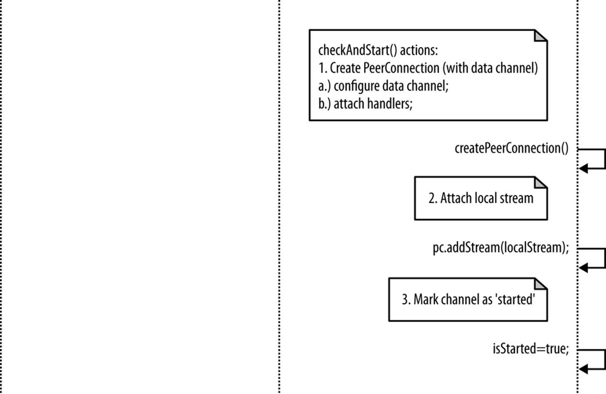
Figure 5-12. Joiner’s actions after getting Initiator’s Offer
When executed by the Joiner, this function creates the Joiner’s PeerConnection object and sets the isStarted flag:
...
function checkAndStart() {
if (!isStarted && typeof localStream != 'undefined' && isChannelReady) {
createPeerConnection();
isStarted = true;
if (isInitiator) {
...
}
}
}
...
As will be explained in Joiner’s Answer, once done with the checkAndStart() function, the Joiner still has to both configure its local PeerConnection and properly build the SDP Answer to be sent back to the Initiator. In the following, we will first briefly discuss the ICE candidate exchanging procedures required on both sides.
ICE Candidate Exchanging
As we already anticipated, one of the main tasks of the signaling server is to enable the exchange of network reachability information between Initiator and Joiner to make it possible to establish a flow of media packets between the two. The Interactive Connectivity Establishment (ICE), RFC5245, technique allows peers to discover enough information about each other’s topology to potentially find one or more communication paths between each other.
Such information is locally gathered by the ICE Agent associated with each RTCPeerConnection object. The ICE Agent is responsible for:
§ Gathering local IP, port tuple candidates
§ Performing connectivity checks between peers
§ Sending connection keepalives
Once a session description (either local or remote) is set, the local ICE agent automatically begins the process of discovering all of the possible candidates for the local peer:
1. The ICE agent queries the operating system for local IP addresses.
2. If configured, it queries an external STUN server to retrieve the public IP address and port tuple of the peer.
3. If configured, the agent also uses the TURN server as a last resort. If the peer-to-peer connectivity check fails, the media flow will be relayed through the TURN server.
Whenever a new candidate (i.e., IP, port tuple) is discovered, the ICE Agent automatically registers it with the RTCPeerConnection object and notifies the application via a callback function (onIceCandidate). The application can decide to transfer each candidate as soon as it is discovered (Trickle ICE) to the remote party or decide to wait for the ICE gathering phase to complete and then send all of the candidates at once.
The sequence of events associated with this specific phase is illustrated in Figure 5-13.
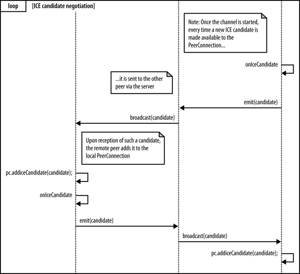
Figure 5-13. Server-mediated ICE candidate exchange procedure
The figure shows that whenever the browser raises an IceCandidate event (because a new ICE candidate has been gathered), the handleIceCandidate() handler is activated. This handler wraps the retrieved candidate inside a dedicated candidate message to be sent to the remote party, via the server:
...
function handleIceCandidate(event) {
console.log('handleIceCandidate event: ', event);
if (event.candidate) {
sendMessage({
type: 'candidate',
label: event.candidate.sdpMLineIndex,
id: event.candidate.sdpMid,
candidate: event.candidate.candidate});
} else {
console.log('End of candidates.');
}
}
...
As usual, the server simply acts as a mediator between the two negotiating parties, as witnessed by the console snapshot in Figure 5-14, which shows how the server relays both the SDP description sent by the Initiator and the ICE candidate addresses retrieved by the two interacting peers.
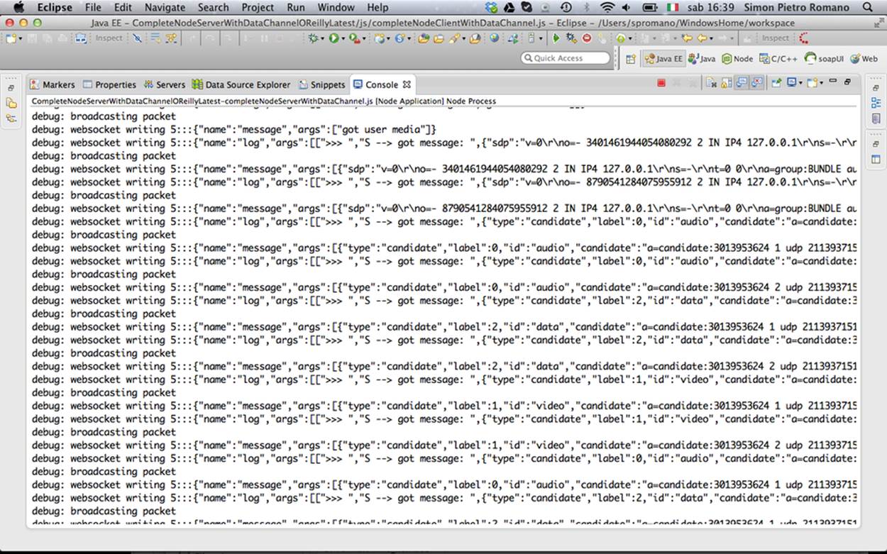
Figure 5-14. Server-mediated negotiation logs
Finally, the JavaScript snippet presented in the following indicates that the two peers add the received candidates to their own PeerConnection objects as soon as they arrive from the signaling server:
...
// Receive message from the other peer via the signaling server
socket.on('message', function (message){
console.log('Received message:', message);
if (message === 'got user media') {
...
} elseif (message.type === 'offer') {
...
} elseif (message.type === 'answer' && isStarted) {
...
} elseif (message.type === 'candidate' && isStarted) {
var candidate = new RTCIceCandidate({sdpMLineIndex:message.label,
candidate:message.candidate});
pc.addIceCandidate(candidate);
} elseif (message === 'bye' && isStarted) {
...
}
});
...
Once the ICE candidates are received by the other peer, the remote session description is set on the RTCPeerConnection object (setRemoteDescription), so the ICE Agent can begin to peform the connectivity check to see if it can reach the other peer.
At this point, each ICE agent has a complete list of both its candidates and its peer’s candidates. It pairs them up. To see which pairs work, each agent schedules a series of prioritized checks: local IP addresses are checked first, then public, and TURN is used as a last resort. Each check is a STUN request/response transaction that the client will perform on a particular candidate pair by sending a STUN request from the local candidate to the remote candidate.
If one of the pair candidates works, then there is a routing path for a peer-to-peer connection. Conversely, if all candidates fail, then either the RTCPeerConnection is marked as failed or the connection falls back to a TURN relay server to establish the connection.
Once a connection is established, the ICE Agent continues to issue periodic STUN requests to the other peer. This serves as a connection keepalive.
TRICKLE ICE
Trickle ICE is a proposed extension to the ICE protocol where instead of waiting for the ICE gathering process to complete, it is possible to send incremental updates to the other peer. This helps accelerate the overall setup phase.
The Trickle ICE mechanism involves the following steps:
§ Both peers exchange SDP offers without ICE candidates.
§ ICE candidates are sent via the signaling channel as soon they are discovered.
§ ICE connectivity checks are run as soon as the new candidate descriptions are available.
Joiner’s Answer
Now that we’re done with ICE candidate exchange, let’s get the train of thought back on track. We were at the point (Joiner Managing Initiator’s Offer) where the Joiner handles Initiator’s Offer by creating its own PeerConnection object. As sketched in Figure 5-15, once done with this, the Joiner first associates the received SDP with the newly instantiated PeerConnection and immediately thereafter calls the doAnswer() JavaScript function.
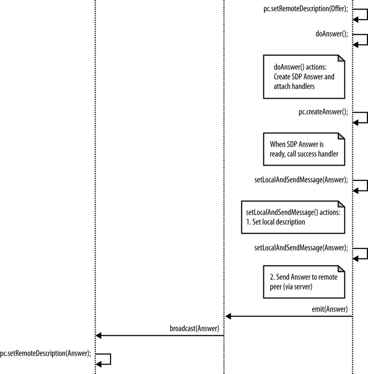
Figure 5-15. Joiner’s Answer to Initiator’s Offer
The snippet below highlights this specific part of the Joiner’s algorithm:
...
// Receive message from the other peer via the signaling server
socket.on('message', function (message){
console.log('Received message:', message);
if (message === 'got user media') {
...
} elseif (message.type === 'offer') {
...
pc.setRemoteDescription(new RTCSessionDescription(message));
doAnswer();
} elseif (message.type === 'answer' && isStarted) {
...
The doAnswer() function basically handles the creation of an SDP Answer to be associated with the received Offer:
...
function doAnswer() {
console.log('Sending answer to peer.');
pc.createAnswer(setLocalAndSendMessage,
onSignalingError, sdpConstraints);
}
...
Similarly to the createOffer() method, the createAnswer() call sets up a success handler to be called as soon as the browser makes the local SDP available. The role of such a handler is to first set the browser-provided SDP as the local session description associated with Joiner’sPeerConnection and then send such a description to the remote party via the signaling server:
...
function setLocalAndSendMessage(sessionDescription) {
pc.setLocalDescription(sessionDescription);
sendMessage(sessionDescription);
}
...
When the Initiator receives Joiner’s Answer from the server, it can properly set it as the remote session description associated with its local PeerConnection object:
...
// Receive message from the other peer via the signaling server
socket.on('message', function (message){
console.log('Received message:', message);
if (message === 'got user media') {
...
} elseif (message.type === 'offer') {
...
} elseif (message.type === 'answer' && isStarted) {
pc.setRemoteDescription(new RTCSessionDescription(message));
} elseif (message.type === 'candidate' && isStarted) {
...
} elseif (message === 'bye' && isStarted) {
...
}
});
...
Going Peer-to-Peer!
We’re finally all set! The two peers have successfully exchanged session descriptions and network reachability information. Two PeerConnection objects have been properly set up and configured thanks to the mediation of the signaling server. As depicted in Figure 5-16, a bidirectional multimedia communication channel is now available as a direct transport means between the two browsers. The server is now done with its task and will be from now on completely bypassed by the two communicating peers.
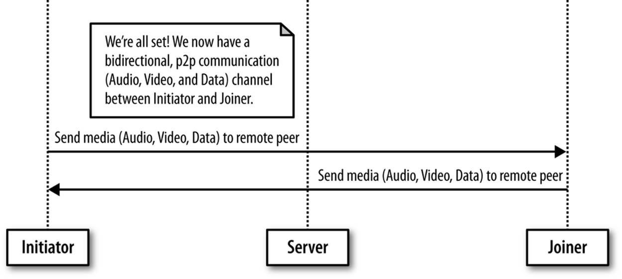
Figure 5-16. Going peer-to-peer after communication setup
The two snapshots in Figures 5-17 and 5-18 show, respectively, the Joiner’s and the Initiator’s windows right after successful channel negotiation. You can see in both figures that each peer now has available local and remote views, as well as two text areas that can be used, respectively, to send direct messages to the remote party and to log direct messages received from the remote party.
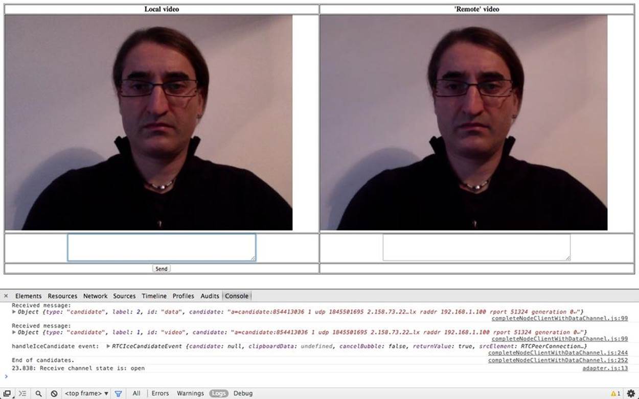
Figure 5-17. Communication established in Chrome: Joiner’s side
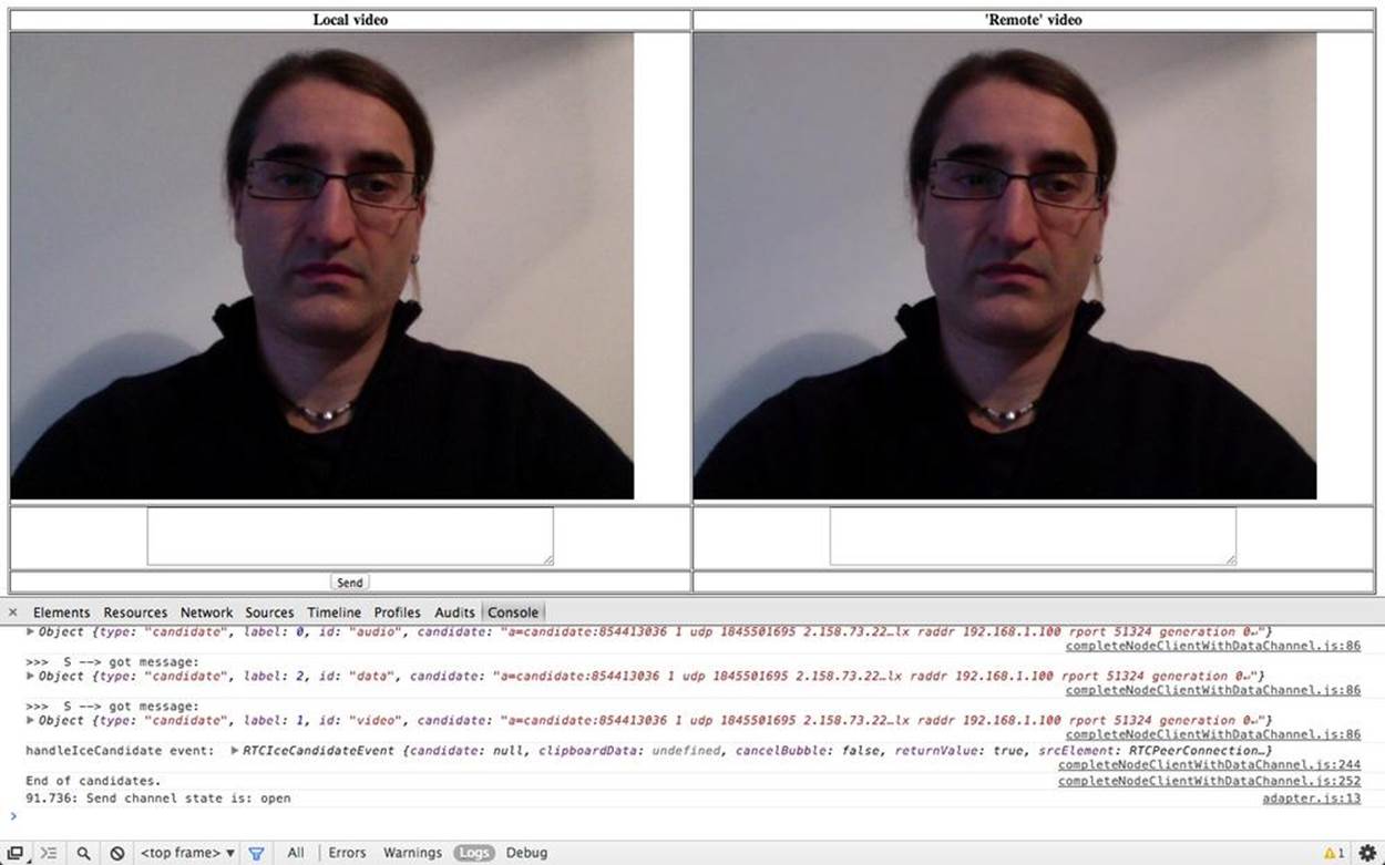
Figure 5-18. Communication established in Chrome: Initiator’s side
Using the Data Channel
In this subsection we will delve into the details of configuring and using the data channel. Actually, the data channel is created by the Initiator as part of the createPeerConnection() function code:
...
function createPeerConnection() {
try {
pc = new RTCPeerConnection(pc_config, pc_constraints);
...
} catch (e) {
...
}
pc.onaddstream = handleRemoteStreamAdded;
pc.onremovestream = handleRemoteStreamRemoved;
if (isInitiator) {
try {
// Create a reliable data channel
sendChannel = pc.createDataChannel("sendDataChannel",
{reliable: true});
trace('Created send data channel');
} catch (e) {
...
}
sendChannel.onopen = handleSendChannelStateChange;
sendChannel.onmessage = handleMessage;
sendChannel.onclose = handleSendChannelStateChange;
} else { // Joiner
pc.ondatachannel = gotReceiveChannel;
}
}
...
The above snippet shows how a number of handlers are associated with the data channel. As an example, we present below the handleSendChannelStateChange() function, which takes care of enabling both the sender’s text area and the Send button as soon as the channel reaches theopen state:
...
function handleSendChannelStateChange() {
var readyState = sendChannel.readyState;
trace('Send channel state is: ' + readyState);
if (readyState == "open") {
dataChannelSend.disabled = false;
dataChannelSend.focus();
dataChannelSend.placeholder = "";
sendButton.disabled = false;
} else {
dataChannelSend.disabled = true;
sendButton.disabled = true;
}
}
...
The sendData() JavaScript function shown below is configured as a handler for the Send button and performs the following actions: (1) it collects text inserted by the user in the sendTextArea; and (2) it sends such text across the instantiated data channel.
...
// Handler associated with Send button
sendButton.onclick = sendData;
...
function sendData() {
var data = sendTextarea.value;
if(isInitiator) sendChannel.send(data);
else receiveChannel.send(data);
trace('Sent data: ' + data);
}
...
Figure 5-19 shows the Initiator’s window right after having sent a text message across the data channel.
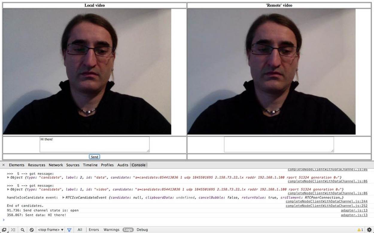
Figure 5-19. Using the data channel: Initiator’s side
Once the message arrives at the other side, the handleMessage() function is triggered. This function, which is shown below, simply takes the transferred data and logs them inside the receiveTextArea element of the HTML page:
...
function handleMessage(event) {
trace('Received message: ' + event.data);
receiveTextarea.value += event.data + '\n';
}
...
This is also shown in the snapshot contained in Figure 5-20.

Figure 5-20. Using the data channel: Joiner’s side
Moving on to the receive channel, as soon as Joiner’s browser raises the dataChannel event, the gotReceiveChannel() function is activated. This handler sets up the receive channel and properly configures it for the management of channel-related events:
...
function gotReceiveChannel(event) {
trace('Receive Channel Callback');
receiveChannel = event.channel;
receiveChannel.onmessage = handleMessage;
receiveChannel.onopen = handleReceiveChannelStateChange;
receiveChannel.onclose = handleReceiveChannelStateChange;
}
...
Figures 5-21 and 5-22 show, respectively, the Joiner sending back an answer to the Initiator across the data channel and the Initiator receiving the answer and logging it inside the data channel text area.
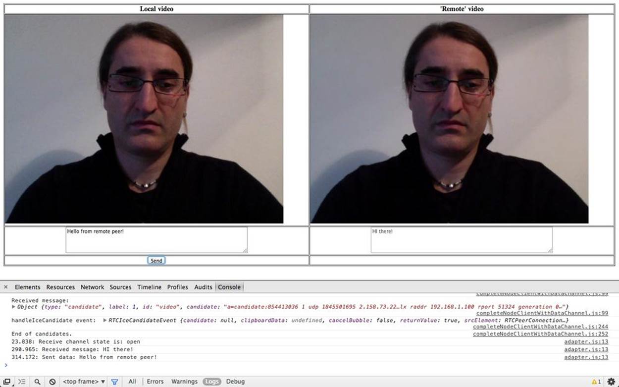
Figure 5-21. Data channel: Joiner answering Initiator’s message
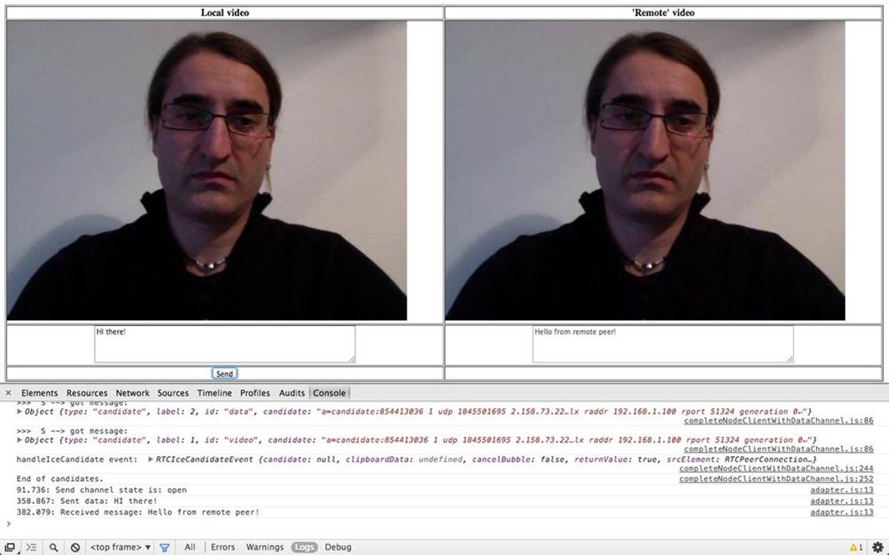
Figure 5-22. Data channel: Initiator getting Joiner’s answer
A Quick Look at the Chrome WebRTC Internals Tool
In this last section, we will provide some information about the WebRTC-specific debugging tools made available by Google Chrome. Indeed, when you’re using a WebRTC-enabled web application, you can monitor its status by opening a new tab and entering chrome://webrtc-internals/inside the tab’s location bar. For the case of our sample application, a snapshot of the webrtc-internals tab is presented in Figure 5-23.
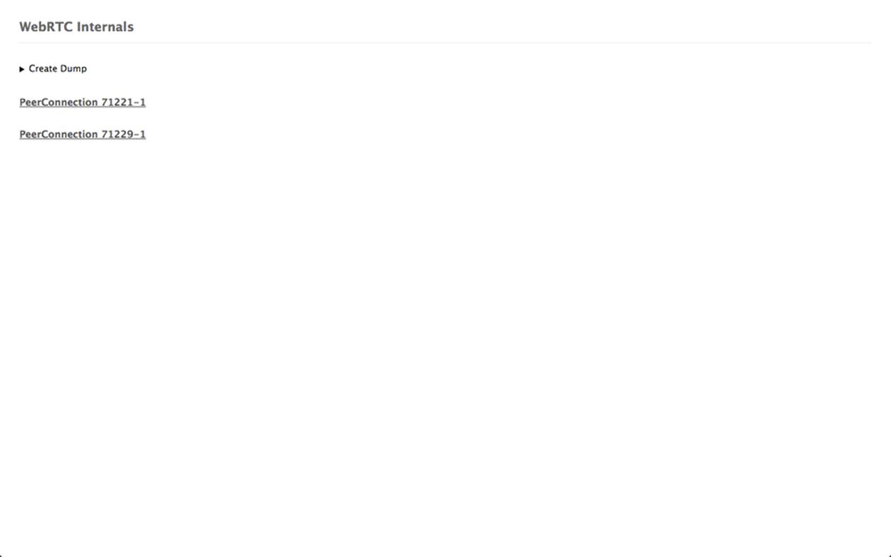
Figure 5-23. Active PeerConnections
As shown in the figure, the logging page reports information about the active PeerConnection objects. In our case, since we’re running both the Initiator and the Joiner on the same machine, we see two active PeerConnection instances, associated, respectively, with the Initiator (PeerConnection71221-1) and with the Joiner (PeerConnection71229-1). By clicking on one of the reported identifiers, fine-grained information about the related PeerConnection appears. As an example, Figures 5-24 and 5-25 show, respectively, the Initiator’s Offer and corresponding Joiner’s Answer in the form of SDP objects. In the same figures, you can also see a list of all events generated by the browser while processing the call.
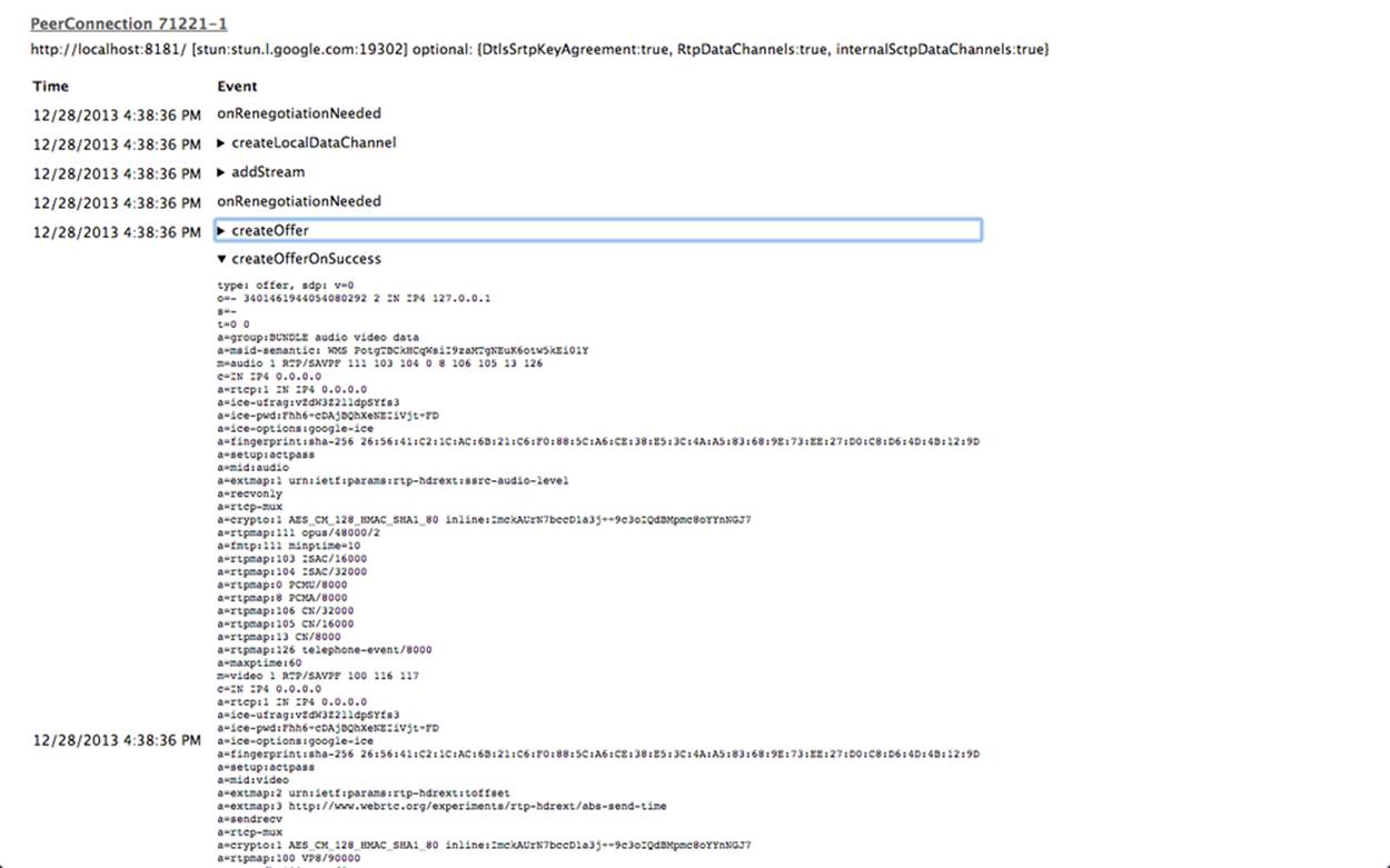
Figure 5-24. The SDP Offer
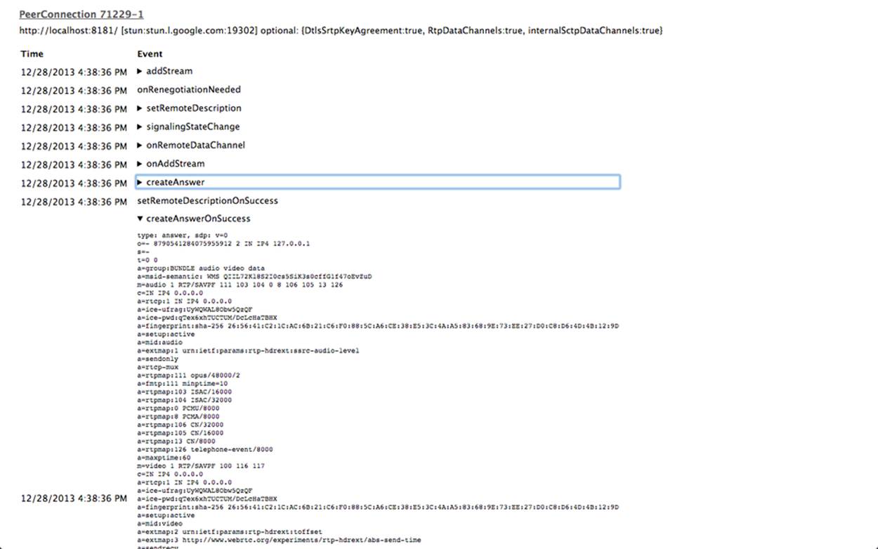
Figure 5-25. The SDP Answer
Chrome is also very good at reporting channel statistics for all of the media involved in a peer-to-peer exchange. As an example, you can see in Figure 5-26 that channel information (channel creation timestamp, browser component handling the channel, local and remote channel certificates for secure information exchanging) is reported for audio, video, and data channels.
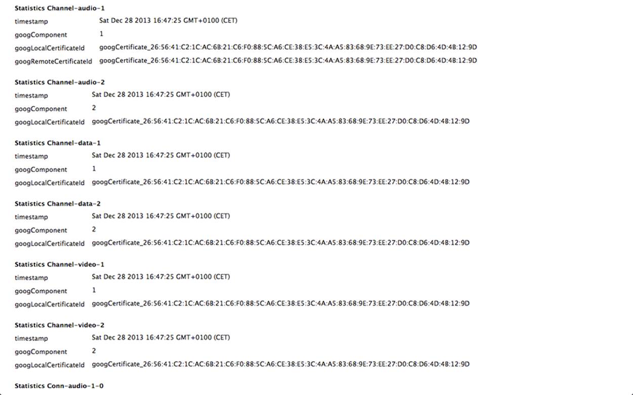
Figure 5-26. Channel statistics in text format
Figure 5-27 instead reports, in graphical format, detailed information about both network-related (estimated available bandwidth, packets sent per second, average round-trip time, etc.) and encoding-related (target encoding bit rate, actual encoding bit rate, etc.) information about media (i.e., both audio and video) streams.
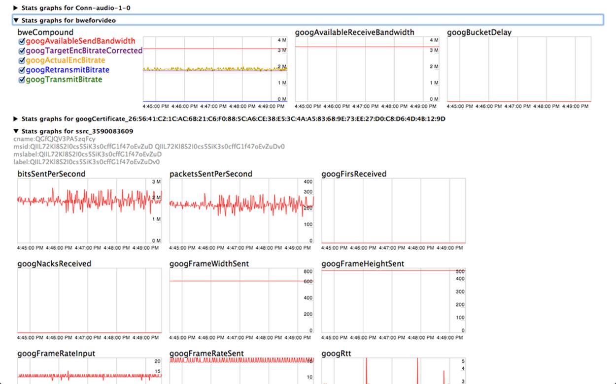
Figure 5-27. Channel statistics in graphical format
Finally, Figure 5-28 illustrates how the browser is actually in charge of both keeping track of ICE protocol machine state changes and generating the related events for the overlying application.
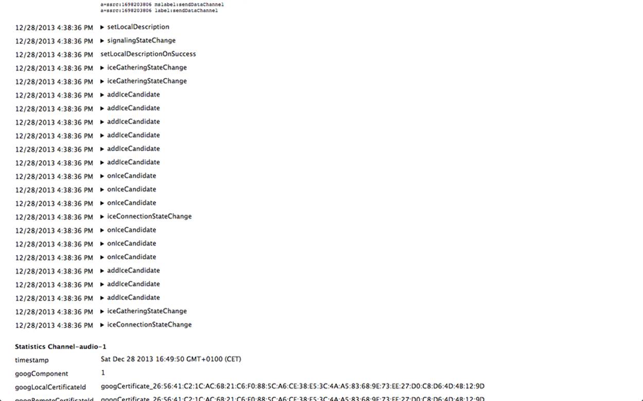
Figure 5-28. Signaling state machine with ICE candidate events
All materials on the site are licensed Creative Commons Attribution-Sharealike 3.0 Unported CC BY-SA 3.0 & GNU Free Documentation License (GFDL)
If you are the copyright holder of any material contained on our site and intend to remove it, please contact our site administrator for approval.
© 2016-2026 All site design rights belong to S.Y.A.