CCNP Security SISAS 300-208 Official Cert Guide (2015)
Part III: Cisco Identity Services Engine
Chapter 9. Initial Configuration of Cisco ISE
This chapter covers the following exam topics:
![]() Describe Native AD and LDAP
Describe Native AD and LDAP
![]() Describe Identity Store Options
Describe Identity Store Options
![]() Network Access Devices
Network Access Devices
![]() ISE Endpoint Identity Configuration
ISE Endpoint Identity Configuration
![]() Troubleshoot Using Cisco ISE Diagnostic Tools
Troubleshoot Using Cisco ISE Diagnostic Tools
![]() Identity Management
Identity Management
When you buy a Cisco Identity Services Engine (ISE) appliance, you can take it out of the box and power on the appliance and it will be ready to control access to the network, right? Wrong. Of course not. Cisco ISE is a very powerful policy engine, and as such it requires a fair amount of preparation to teach it how to communicate in the company’s environment.
We are not simply talking about the standard requirement of “this device requires a valid IP address before it can communicate on a network.” Although that is absolutely a requirement for Cisco ISE, there is so much more.
Cisco ISE will need to be configured for working domain name resolution (DNS), for correct time synchronization (NTP), and to have a valid and resolvable fully qualified domain name (FQDN) that any network-attached device might use to resolve the address. Cisco ISE will need a certificate installed that has been signed by the company’s root certificate authority or a public certificate authority. It will also need to be configured with the addresses and secret keys of all the network devices that will use it—and most likely be joined to an Active Directory (AD) infrastructure to use as one of the identity sources.
The blueprint for this exam focuses mainly on the state of Cisco ISE after the administrative graphical user interface (GUI) is running and available. However, critical steps during the initial installation can make the overall deployment successful or make it more difficult. Therefore, this chapter focuses on all of it.
“Do I Know This Already?” Quiz
The “Do I Know This Already?” quiz enables you to assess whether you should read this entire chapter thoroughly or jump to the “Exam Preparation Tasks” section. If you are in doubt about your answers to these questions or your own assessment of your knowledge of the topics, read the entire chapter. Table 9-1 lists the major headings in this chapter and their corresponding “Do I Know This Already?” quiz questions. You can find the answers in Appendix A, “Answers to the ‘Do I Know This Already?’ Quizzes.”
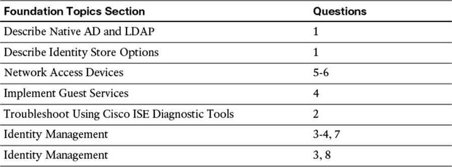
Table 9-1 “Do I Know This Already?” Section-to-Question Mapping
Caution
The goal of self-assessment is to gauge your mastery of the topics in this chapter. If you do not know the answer to a question or are only partially sure of the answer, you should mark that question as wrong for purposes of the self-assessment. Giving yourself credit for an answer you correctly guess skews your self-assessment results and might provide you with a false sense of security.
1. Which rights and permissions are required for the account used to join Cisco ISE to the Active Directory domain?
a. Search Active Directory, Remove workstation from domain, Change passwords
b. Write to Active Directory, Add workstation to organizational unit, Read properties of computer objects
c. Search Active Directory, Add workstation to domain, Set attributes on the new machine account
d. Write to Active Directory, Add workstation to domain, Read properties of computer objects
2. Which CLI command lists all the ISE processes and their statuses?
a. show status ise
b. show application status ise
c. show application status
d. show version
3. Which two functions does a certificate fulfill when used with HTTPS and EAPoverLAN?
a. Authenticates the server to the client, and the encryption method is embedded in the transform-set field within the certificate.
b. Identifies the client to the NAD and is used as the basis for the encrypted transport between the client and the NAD.
c. Authenticates the server to the client and is used as the basis for the encrypted transport between the client and server.
d. Authenticates the client to the NAD, and the encryption method is embedded in the transform-set field within the certificate.
4. True or False? When submitting a certificate signing request (CSR), the CSR and the private key are sent to the signing certificate authority (CA), so the CA can sign the key-pair.
a. True
b. False
5. True or False? Settings such as RADIUS shared secret keys and SNMP strings can be set on a per Network Device Group (NDG) level.
a. True
b. False
6. What is a valid use of network device groups?
a. Use NDG as the condition by which to build different policy sets for the staged deployment of ISE.
b. Use the incoming authentication protocol type to route the authentication to a network device group that is able to process that authentication type.
c. Use the NDG to determine to which ISE policy node to route the authentication request.
d. The result of an authorization policy will allow the user to log in and control devices within the assigned network device group.
7. True or False? Local endpoint identity groups should be created per endpoint profile instead of using the attribute itself.
a. True
b. False
8. True or False? Cisco ISE 1.2 can join 1 Active Directory Forest and process authentications for any domain in the forest with 2-way trusts.
a. True
b. False
9. What is the purpose of a certificate authentication profile (CAP)?
a. Defines which CA to use for revocation checking via either certificate revocation lists (CRLs) or online certificate status protocol (OCSP).
b. Used with MSCHAPv2 for a client to validate the authentication server.
c. Serves as the identity source for certificate authentications and defines the field of a certificate whose data will be extracted and used as the principle identity for the authorization process.
d. Used with EAP-FAST to allow for faster reauthentications and secure transport without the use of X.509 certificates.
10. True or False? It is critical to use Network Time Protocol (NTP) to ensure the time is synchronized correctly between Cisco ISE and Microsoft Active Directory.
a. True
b. False
Foundation Topics
Cisco Identity Services Engine Form Factors
Before the Cisco Identity Services Engine can be configured, it must first be installed. The installation of Cisco ISE is beyond the scope of the exam blueprint, and therefore is behind the scope of this book. There are two form factors for Cisco ISE. There is a physical appliance called the Cisco Secure Network Server (SNS). The SNS appliance is a multipurpose appliance and is used for not only Cisco ISE, but also Cisco Secure Access Control Server (ACS) and Cisco Network Admission Control (NAC) Appliance.
Cisco ISE is also available as a virtual appliance. It is important to recognize that a virtual appliance is different from a traditional virtual machine. How is it different? A virtual machine is meant to leverage the shared physical compute resources of a host server. A virtual appliance must be configured to be an exact replica of the physical appliance it is representing. That means the hardware cannot be oversubscribed and reservations for the memory and CPU must be configured at equal values to the physical SNS appliances.
Why is this so important? The authors of this book have both been involved in a number of escalation cases where the root of the problem that the customer ran into was the misconfiguration of the VMware virtual machine(s) itself. The main misconfigurations are no resource reservations were set for the memory and CPU; the VM storage was much slower than the physical drives of the SNS appliance; and delayed writes causing database corruption. Please use that as a lesson to ensure the virtual appliances are always configured with the correct reservations and storage in place.
For instructions on installation and configuration, see the Cisco Identity Services Engine Installation guides at http://www.cisco.com/c/en/us/support/security/identity-services-engine/products-installation-guides-list.html.
Bootstrapping Cisco ISE
As stated in the introduction, Cisco ISE is a powerful policy engine, and as such, it requires a fair amount of preparation to teach it how to communicate in the company’s environment.
The SNS Appliance will come with Cisco ISE preinstalled and waiting at the setup screen (as shown in Figure 9-2). For the virtual appliance and for any time you are installing from a DVD (or .iso file), you will see the installation choices menu displayed in Figure 9-1.
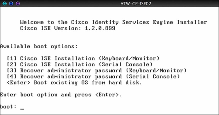
Figure 9-1 Installation choices.
The underlying operating system (OS) that will be installed is a customized Linux called the Cisco Application Development Environment Operating System (ADE-OS). After the OS has completed installing, the appliance will restart and boot into the setup prompt, as shown in Figure 9-2.
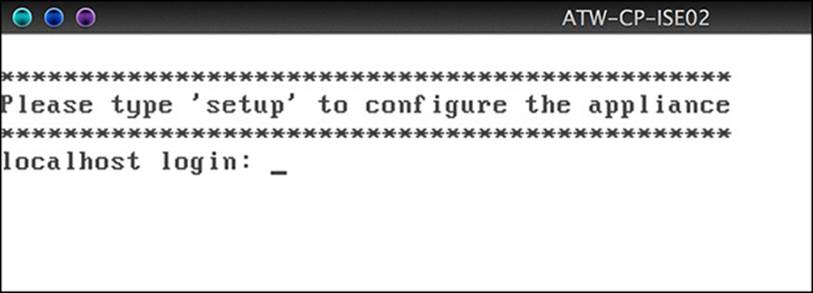
Figure 9-2 Setup prompt.
Typing setup will launch the command-line setup wizard. Following the prompts, enter all the bootstrapping information the setup wizard asks for, as shown in Figure 9-3.
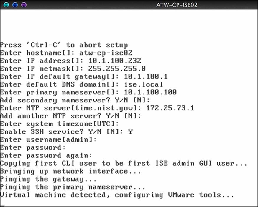
Figure 9-3 CLI Setup Wizard.
After the settings have been validated, the ISE application itself is installed. This will take quite a bit of time, so at this point you should go drink a few gallons of coffee. After the ISE application is fully installed, the device will reboot. You can log in to the CLI one more time and ensure that the ISE application has started successfully before attempting to connect to the web interface. The command show application status ise lists all the ISE processes and their statuses, as shown in Figure 9-4. When the application service is running, ISE is ready for you to connect to the administrative GUI.
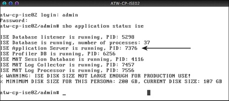
Figure 9-4 Output of the show application status ise command.
You connect to the Cisco ISE GUI using secure HTTP (HTTPS), using the following URL: https://<ise-fqdn>/admin/. Upon connecting to the ISE GUI the first time, your web browser will most likely present an error about the certificate being unknown or untrusted, as shown in Figure 9-5. This error message is due to the self-signed certificate that is created during installation.
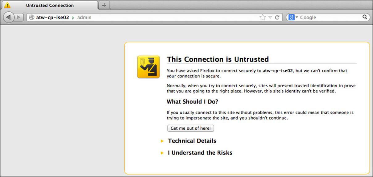
Figure 9-5 Untrusted certificate error.
Accept and trust this certificate to gain access to the administrative GUI login, as shown in Figure 9-6. Enter the username and password entered during the installation setup wizard.
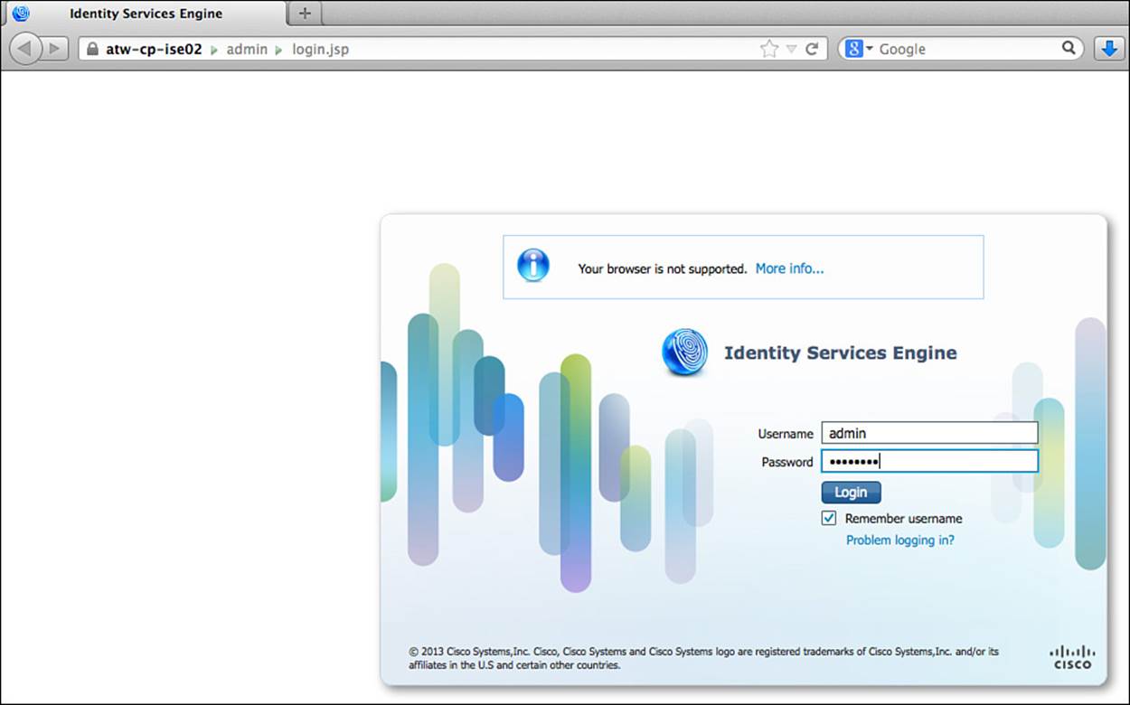
Figure 9-6 Administrative login.
Where Are Certificates Used with the Cisco Identity Services Engine?
When you connect to a website secured with Secure Sockets Layer (SSL, a.k.a.: HTTPS), the website will use an x.509 certificate to establish that secure communication. The certificate is used for more than one function:
1. To prove “identity” of the website
2. To serve as the basis of encryption between the client (web browser) and the website
Figure 9-7 illustrates the process of securing a website. Numerous web portals are hosted on ISE, including the administrative portal, which was displayed in Figure 9-6. In addition, there are many end-user–facing portals for web authentication, endpoint management, and other uses. All portals on ISE require encryption by default. In other words, all portals in ISE will use HTTPS, and a certificate on ISE will be used to secure that communication.
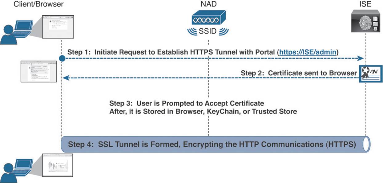
Figure 9-7 Securing Web communications with SSL.
Certificates are also used to secure Extensible Authentication Protocol communications, as described in great detail in Chapter 4, “EAP over LAN (also Known as 802.1X).” Much like the SSL communication with websites, certificates are used to form a Transport Layer Security (TLS) tunnel between the endpoint and the RADIUS server, within which EAP authentication will occur, as shown in Figure 9-8. Much like the secure-HTTPS example, the x.509 certificate has multiple functions with EAP as well. It is used to identify the RADIUS server to the client (supplicant) as well as form the basis of the encrypted communication.
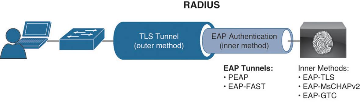
Figure 9-8 Securing EAP communications with TLS.
Self-Signed Certificates

When initially installing ISE, the application will generate a self-signed certificate, meaning no certificate authority (CA) was used to sign the certificate and vouch that it should indeed be trusted. By default, many browsers and operating systems alike come with a number of preinstalled CA certificates from the more popular CAs. Because a well-known and well-trusted CA was not used to sign this self-signed certificate, clients (browsers and supplicants alike) will not trust the certificate and warning messages similar to the message shown in Figure 9-5 will be displayed.
Note
To join ISE nodes in what is commonly referred to an ISE cube, each ISE node must trust the certificate(s) used by the other ISE nodes.
Numerous complexities are involved with running a production deployment with self-signed certificates. The first that will present itself is that each ISE node will need to trust each other’s ISE node (a problem that will increase itself exponentially as the deployment grows). For this and many other reasons, it is always recommended to use signed certificates. This does not mean the certificate must be signed by a public trusted root; a company’s own internal CA would suffice nicely as well.
CA-Signed Certificates
There are a few ways to implement a signed certificate on a device. If you have the public and private keys (known as the key pair) backed up and stored somewhere secure, those keys could simply be imported into whatever device you want to use those keys. This is not normally what happens when first installing ISE.
When initially installing ISE, a more common way to receive a signed certificate from a CA is to generate a certificate signing request (CSR) and then submit that CSR to the CA. The CA then signs the public key based on the CSR and returns that public key to you, as shown in Figure 9-9.
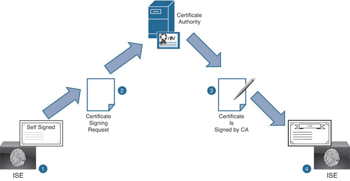
Figure 9-9 Stages of certificate signing overview.
For ISE, all certificate management is handled within the ISE GUI under Administration > System > Certificates. The initial screen displays the local certificates, which displays the default self-signed certificate, as shown in Figure 9-10.
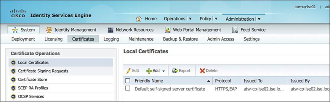
Figure 9-10 Administration > System > Certificates > Local Certificates.
Initiate the generation of a CSR by clicking Add > Certificate Signing Request, as shown in Figure 9-11.
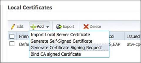
Figure 9-11 Local Certificates > Add > Generate Certificate Signing Request.
Fill in the Certificate Subject field for the CSR after the Generate Certificate Signing Request page is displayed in the main window, as shown in Figure 9-12. A number of fields can make up the certificate subject and should be separated by commas. These include
![]() Common Name (CN)—This is the only mandatory field for the certificate subject. The CN should be a fully qualified domain name (FQDN) that will resolve via DNS to an IP address of the ISE node. The standard would be to use the hostname and domain name configured during the initial setup of ISE (ex: atw-cp-ise02.ise.local).
Common Name (CN)—This is the only mandatory field for the certificate subject. The CN should be a fully qualified domain name (FQDN) that will resolve via DNS to an IP address of the ISE node. The standard would be to use the hostname and domain name configured during the initial setup of ISE (ex: atw-cp-ise02.ise.local).
Note
Pay close attention to capitalization because it will matter when binding the signed certificate.
![]() Organization (O)—This should be the organization the certificate is meant to represent; in other words, the name of the company that is implementing ISE.
Organization (O)—This should be the organization the certificate is meant to represent; in other words, the name of the company that is implementing ISE.
![]() Organizational Unit (OU)—This field should represent the division of the company that is controlling the device for which the certificate is being used.
Organizational Unit (OU)—This field should represent the division of the company that is controlling the device for which the certificate is being used.
![]() Locality (L)—Another field for defining the entity, it is often used to denote the city where the entity resides.
Locality (L)—Another field for defining the entity, it is often used to denote the city where the entity resides.
![]() State (ST)—The state or province in which the entity resides.
State (ST)—The state or province in which the entity resides.
![]() Country (C)—The country in which the entity resides.
Country (C)—The country in which the entity resides.
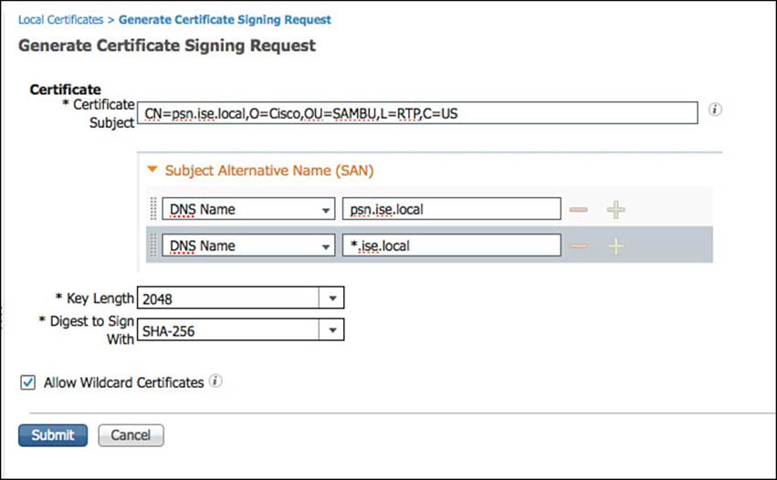
Figure 9-12 CSR form.
There are many more optional fields, or attributes. The only required one is the Common Name (CN). Another section of certificate attributes that the ISE GUI enables customization of is the Subject Alternative Name (SAN) field. The SAN field is meant to carry a number of attributes, each designed to aid in the identification of the certificate.
When presented with a certificate, a client will compare the name of the host with the CN field of the certificate subject. If the hostname or FQDN used to reach the host does not match what is in the CN field, it will cause a certificate name mismatch. For example, if a secure website is hosted at https://www.ciscopress.com and the subject of that certificate has a CN=www.ciscopress.com, the name and the CN will match. However, the FQDN www.ciscopress.com resolves to an IP address of 159.182.165.54. That same address also might resolve to the FQDN ofwww.pearsonpublishing.com. If you were to enter the URL of https://159.182.165.54 or https://www.pearsonpublishing.com into the web browser, a certificate mismatch error would occur.
This brings the conversation to one of wildcard certificates. A wildcard certificate is one that uses a wildcard notation (an asterisk and a period before the domain name) and enables the certificate to be shared across multiple hosts in an organization. A sample CN value for a wildcard certificate’s Subject Name would look like the following:
*wolandheffner.com
If you configure a wildcard certificate to use *wolandheffner.com, that same certificate can be used to secure any host whose DNS name ends in “wolandheffner.com”, such as:
aaa.wolandheffner.com
psn.wolandheffner.com
mydevices.wolandheffner.com
sponsor.wolandheffner.com
Although a wildcard certificate would solve the issue for a different hostname in the CN, it would still require the domain name to be the same. So, why doesn’t ISE just use wildcard certificates for everything? Wildcard certificates are not used for all functions because Microsoft supplicants will not trust wildcard certificates for EAP communications.
As an alternative to wildcard certificates, focus can shift to the Subject Alternative Name (SAN) field, which was designed to allow for these name mismatches. The certificate is authorized to represent the name in the CN field, as well as the name(s) in the SAN field. The options could be DNSName or IPAddress to match a different FQDN or even the IP address of the host. The RFC defining the x.509 certificate fields (RFC 6125) defines the requirement for the FQDN from the CN field to also be listed as a DNSName in the SAN field.
As shown in Figure 9-12, a wildcard value also can be added as a DNSName entry in the SAN field. This provides a best of both worlds approach for matching multiple values. It enables the use of the same private and public key-pair to be installed across all the ISE nodes, which enables a much smoother user experience with mobile devices.
After clicking Submit, a public and private key pair is created. The private key will be kept secret and never distributed to any third party. The public key and the X.509 information are then combined to form the CSR. This CSR is stored under Administration > System > Certificates > Certificate Signing Requests, as shown in Figure 9-13.
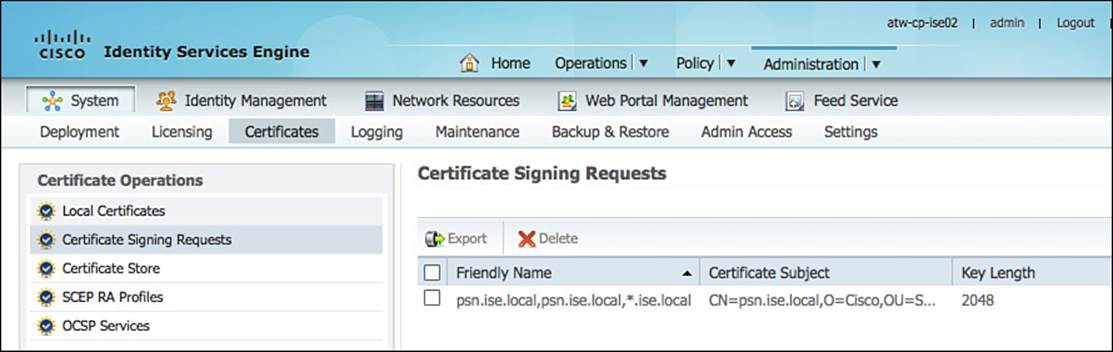
Figure 9-13 Administration > System > Certificates > Certificate Signing Requests.
From here, you will select the certificate signing request and click Export. This will prompt you to save the CSR to your local drive, as shown in Figure 9-14.
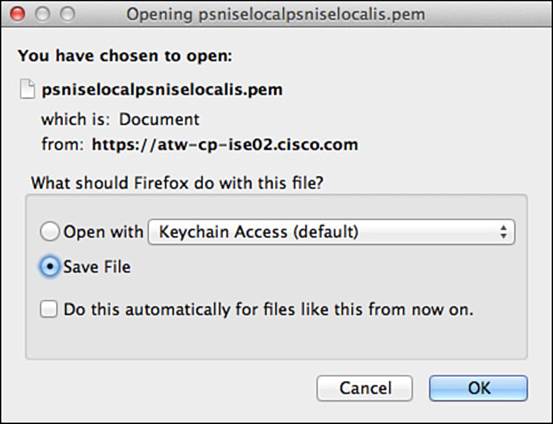
Figure 9-14 Downloading the CSR.
The CSR will be a Base-64 encoded, plain-text format file, known as a PEM file. This can be opened in a standard text editor, as shown in Figure 9-15. Copy all the text including the “-----BEGIN CERTIFICATE REQUEST-----” and the “-----END CERTIFICATE REQUEST-----”, but do not include any extra spaces (if they exist).
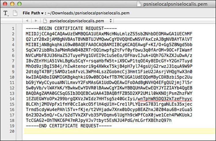
Figure 9-15 Certificate authority.
Open a web browser and navigate to the CA. In this chapter we are using the CA built in to Active Directory—for example, http://atw-cp-ad.ise.local/certsrv, which is shown in Figure 9-15. If you are not using a CA server, a different process might be required.
Next, click Request a Certificate, as shown in Figure 9-16.
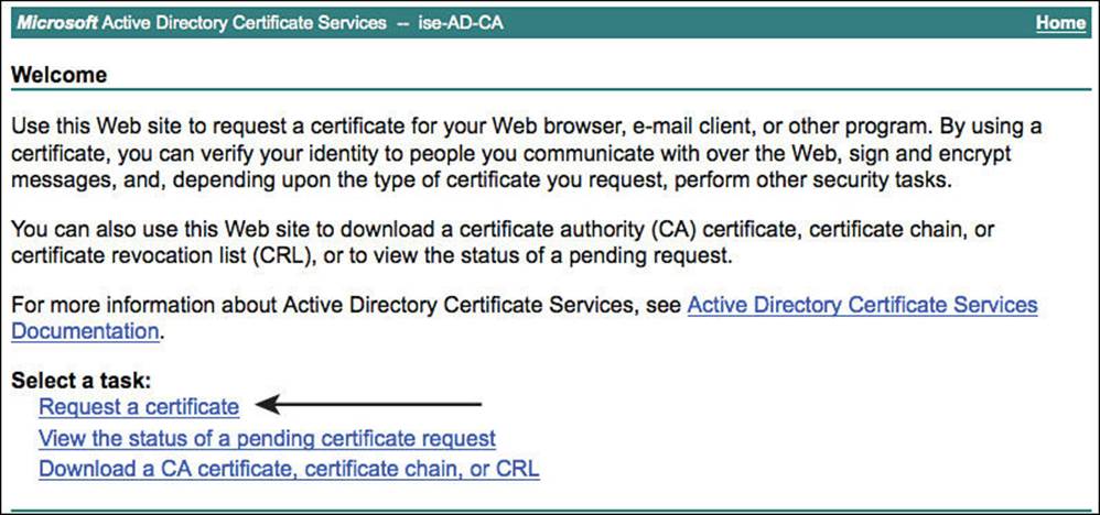
Figure 9-16 Request a certificate.
Select the Advanced Certificate Request, as shown in Figure 9-17.
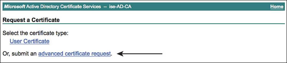
Figure 9-17 Advanced certificate request.
Paste the contents of the CSR into the form, ensuring there are no extra spaces. Select the Web Server certificate template from the drop–down list, and click Submit, as shown in Figure 9-18.
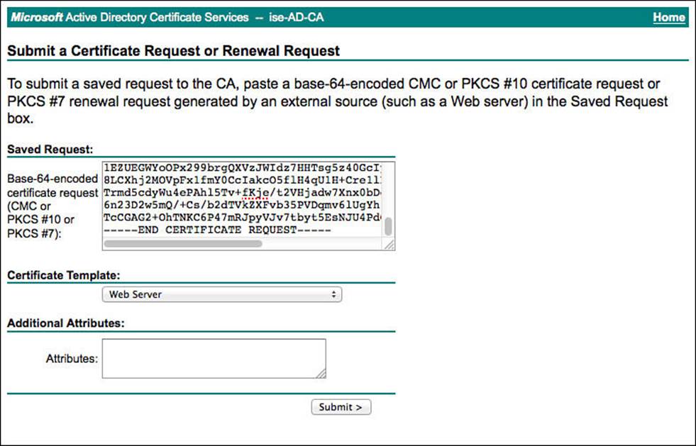
Figure 9-18 Submit the certificate signing request.
Select the Base 64 encoded option. This is the PEM format. Then click Download Certificate, as shown in Figure 9-19.
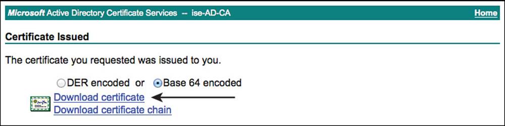
Figure 9-19 Download the signed certificate.
Note
Do not download the certificate chain. The best practice from Cisco is to import all certificates separately, instead of using certificate chains (PKCS files). This is due to the difference in behavior of the numerous client supplicants and how those supplicants authenticate the certificate chains.
Navigate back to the main page of the certificate authority, and click Download a CA Certificate, Certificate Chain, or CRL. This is where you will download the public certificate of the CA itself.
Select Base 64 and click Download CA Certificate, as shown in Figure 9-20.
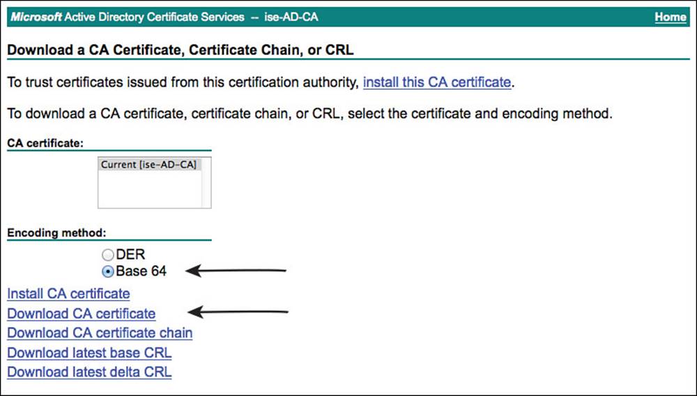
Figure 9-20 Download the CA’s public certificate.
Now you will import the CA’s certificate into the ISE trusted store by navigating to Administration > System > Certificates > Certificate Store in the ISE GUI, as shown in Figure 9-21.
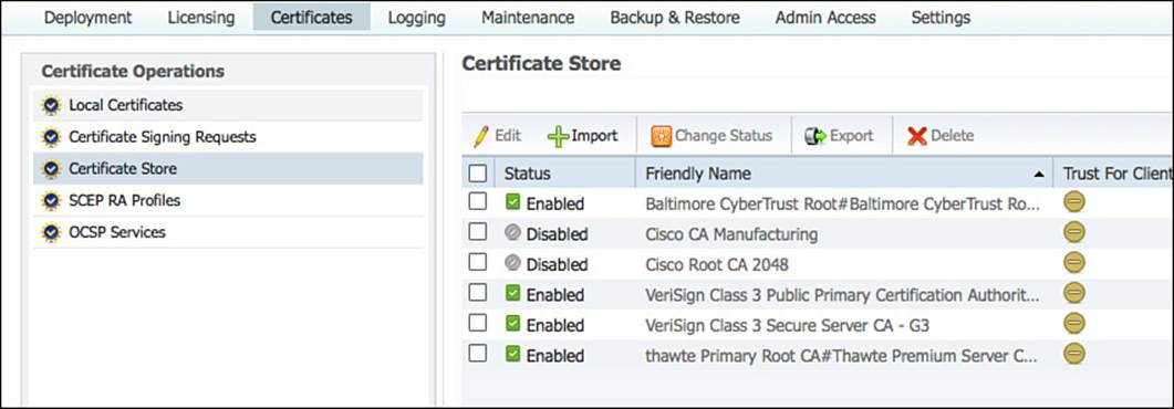
Figure 9-21 Administration > System > Certificates > Certificate Store.
This is the location of all certificates that ISE will trust, for which functions certificates from that CA are trusted, and where the revocation checking is defined.
Click Browse and select the CA’s certificate. Provide a friendly name to help identify the certificate in the list, and click Trust for Client Authentication or Secure Syslog Service. Then click Submit, as shown in Figure 9-22.
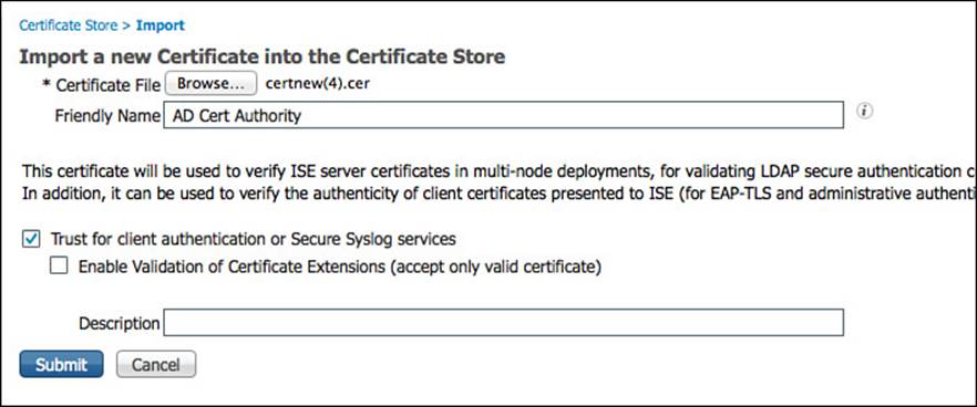
Figure 9-22 Importing the CA’s certificate to be trusted.
Now that ISE will trust certificates signed by the Active Directory CA, it is time to bind the CA signed identity certificate to the CSR for ISE to now use the certificate. Navigate to Administration > System > Certificates > Local Certificates. Click Add > Bind CA Signed Certificate.
Click Browse and select the signed identity certificate. Provide a friendly name, and ensure the Allow Wildcard Certificates check box is checked if you provided a CN that is not the exact same as the ISE node’s FQDN. Select both the EAP and HTTPS check boxes for the use of this certificate, and click Submit. Figure 9-23 shows the Bind CA Signed Certificate screen.
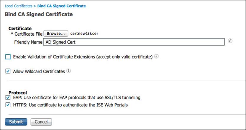
Figure 9-23 Bind CA signed certificate.
The ISE node will now restart all services to use the newly applied certificate. Upon your next login, you also can delete the CSR and the original self-signed certificate because they are no longer needed. When you connect after the reboot, you will also notice that the certificate used to protect and identify the ISE admin portal is now the signed certificate. Figure 9-24 illustrates the identity certificate in use.
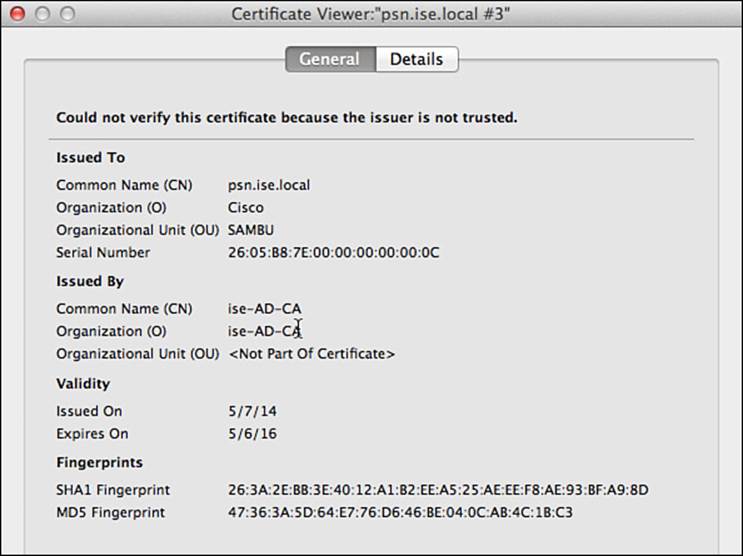
Figure 9-24 The signed certificate in use.
There is one more step that should be completed for various reasons. The public and private key-pair should be exported and stored in a secure location. Why? This is a recommended step to ensure that the same certificates can be used on any additional ISE nodes and to ensure there is a safe backup in case of an emergency that requires the ISE node to be rebuilt.
From the ISE GUI, navigate to Administration > System > Certificates > Local Certificates. Select the signed-certificate, and click Export. Select Export Certificate and Private Key, and provide a secure password that can be used to unencrypt the keys for future use, as shown in Figure 9-25.
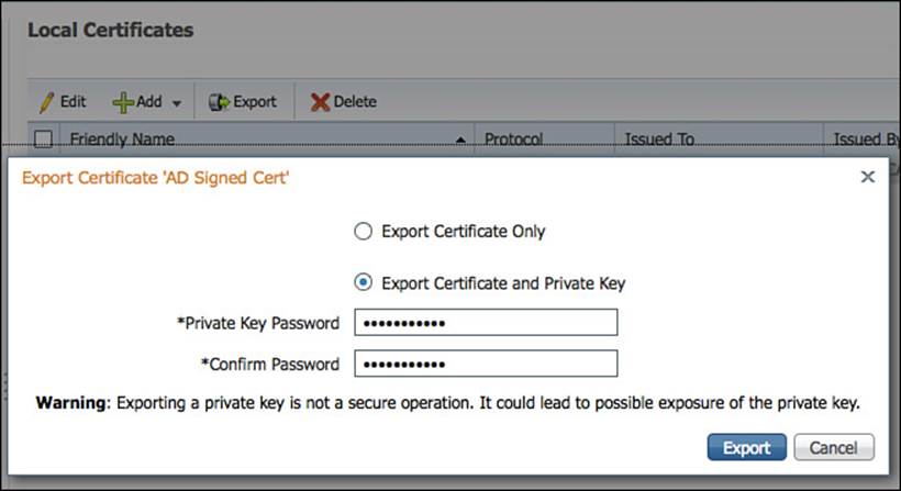
Figure 9-25 Exporting the private/public key pair.
This completes the certificate portion of the ISE installation and bootstrapping.
Network Devices
Cisco ISE is a policy server. In industry standard terms, ISE would be considered a policy administration point (the admin node) and a policy decision point (the PSN). The policy enforcement point is the network access device (NAD). The NAD is the device that applies the actual access control to the endpoint.
This device, or more specifically the device’s capabilities, is a critical part of any secure network access strategy. The more capable the network access devices (switch, wireless controller, and VPN concentrator) are, the more flexibility and power the ISE admin will have to accomplish the business goals.
Network Device Groups
Before adding network access devices to ISE, it is highly recommended to create some logical network device groups (NDGs), located under Administration > Network Resources > Network Device Groups. These groups can be a powerful tool when used correctly. With the use of NDGs, policy can be created based on the type of network device, its location, or any other logical grouping that an organization might want.
ISE is prebuilt with two top-level groups named All Device Types and All Locations. An ISE administrator can create other top-level groups as required. Examples of other top-level groups could be Line of Business, Deployment Stage, and so on—basically anything that would be an organizational unit for your business or deployment structure.
Figure 9-26 displays an example NDG hierarchy.
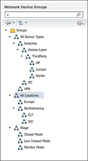
Figure 9-26 Sample NDG structure.
Network Access Devices
Now that the NDG structure is in place, it is time to add the network access devices themselves. When you add a NAD (switch, wireless LAN controller, or VPN) to ISE, you are teaching ISE about its IP address, configuring a shared secret key for the RADIUS communication, and maybe even configuring some SNMP strings to pull data from that device (think profiling data). This process is what teaches ISE how to communicate to the device that will be doing all the enforcement of ISE policy.
To add a NAD to ISE, navigate to Administration > Network Resources > Network Devices, and click Add. The network device is added to ISE as an object. That object has numerous important attributes that configure ISE to uniquely identify each NAD, as well as the shared secret key, SNMP community strings, and TrustSec configuration. The shared secret key must match the configured key on the NAD exactly.
As shown in Figure 9-27, each NAD object must be configured with one or more IP address that ISE will use to communicate with the NAD, as well as identify which NAD is the source of an incoming request. An entire subnet can be associated with a single entry, isolating which NAD on the configured subnet had authenticated the endpoint; however, this might make troubleshooting difficult in the future. This screen is also where the NDGs will be selected.
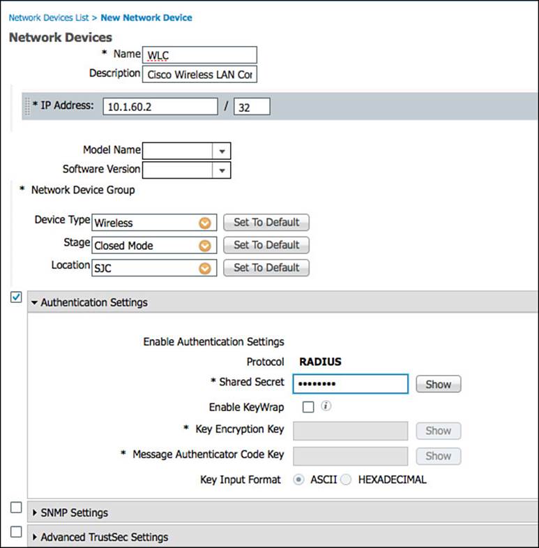
Figure 9-27 Adding a network device.
Each NAD can be assigned to one NDG of each type. In other words, one Location group; one Device Type group; and one of each manually created top-level NDG, such as Stage.
The important section labeled Authentication Settings is where the RADIUS shared secret is configured. The SNMP Settings section configures the SNMP community for the network device, which ISE will use for querying the NAD for profiling attributes such as CDP and LLDP cache information. Only configure the SNMP settings for devices that do not use the Device Sensor to send ISE profiling data within RADIUS accounting packets. The Advanced TrustSec Settings is where security group tag (SGT) and network device admission control (NDAC) settings.
Note
It is possible and common to use a comma-separated value (CSV) file to do bulk imports of NDGs and NADs. However, these functions are beyond the scope of this book.
Local User Identity Groups
Local users and local user groups are a form of identity store. Identity stores are covered in much more detail in Chapter 3, “Identity Management.” However, it’s important to cover these in this section for the instances where local users and groups are needed during initial setup for a small proof of concept or other small deployment.
Local user groups are used with local users, including guest users. The groups can be used to define specific levels of access and other attributes that should be applied to a group of local users instead of individuals. Sample uses of groups could be for local sponsors of guest users, guest user types, and more. These special groups are covered more in Chapter 14, “Deploying Guest Services.”
Figure 9-28 displays the prebuilt groups as can be shown under Administration > Identity Management > Groups > User Identity Groups. These identity groups may be used directly in the authorization policies and even have a special location within the policy where a user or endpoint identity group can be used.
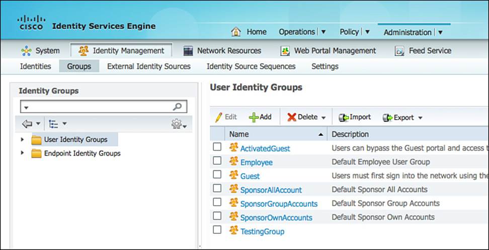
Figure 9-28 Prebuilt user identity groups.
Note
Unlike endpoint identity groups, user identity groups cannot be nested. This means you cannot create a group that is a member of another group.
Local Endpoint Groups
Endpoints and endpoint identity groups are another form of identity store. Endpoint identities are covered in much more detail in Chapter 15, “Profiling.” These groups are best used for what many organizations call MAC address management. For example, an endpoint identity group can be created with the name Corporate Asset, and a list of MAC addresses of corporate-owned tablets, laptops, desktops, and other devices can be added to the group.
Note
An endpoint can exist in one and only one identity group. However, identity groups can be nested. For example, you can create an identity group named “iPads” that is a member of the “Corporate Asset” group.
Before ISE 1.2, an administrator had to create a matching endpoint identity group for every profile that the administrator wanted to use in a policy. In ISE 1.2 and above, the profile attribute itself is used in the Authorization Policy, negating the need to waste endpoint identity groups on a profile. Now they can be used for pure MAC address management.
Figure 9-29 shows the preconfigured endpoint identity groups located under Administration > Identity Management > Groups > Endpoint Identity Groups. Notice how Cisco-IP-Phone and Workstation are nested within the Profiled group. These are legacy groups that are left over from the pre-1.2 versions.
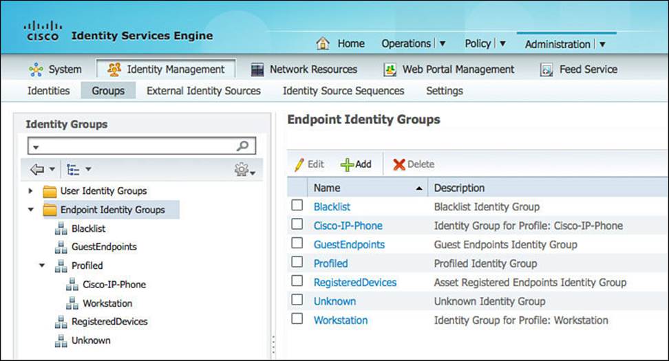
Figure 9-29 Preconfigured endpoint identity groups.
Local Users
Found within Administration > Identity Management > Identities > Users, the local users are another identity store where user accounts can be created for use with network logins, sponsor accounts for guest users, and sometimes to create test accounts for service probes. Although you can use local accounts for an entire deployment of ISE, it is not very common. The majority of deployments use an external identity store such as Active Directory as the “single source of truth”—while leveraging locally configured users for administrative purposes.
For more on identity stores, refer to Chapter 3.
External Identity Stores
Even though it would be easy to continue to think of a policy server maintaining all the user accounts locally, this would not be practical, nor would it succeed in today’s world. With large enterprises, there is usually a need for what is commonly called a single source of truth for identity. Often many different identity stores are used within an organization.
You will most likely need to configure one or more external identity sources during the configuration of your ISE deployment. The most common external identity sources and how to configure them are described in the following sections. For more on identity source types, refer to Chapter 3.
Active Directory
Microsoft Active Directory is the single most common external identity store shown with ISE deployments. Cisco ISE will join AD, creating a machine account and using native AD communications to query the identity store for user accounts and their attributes.
Cisco ISE 1.2 will join a single AD domain and can query other domains within the AD forest, as long as the trust relationships exist. For more on AD as an identity source, please refer to Chapter 3.
Prerequisites for Joining an Active Directory Domain
To join Cisco ISE to an AD domain, you don’t have to use the administrator account. Any account can be used as long as it has the following rights and permissions:
![]() Search Active Directory (to see whether ISE machine account already exists).
Search Active Directory (to see whether ISE machine account already exists).
![]() Add workstation to domain (if one does not already exist).
Add workstation to domain (if one does not already exist).
![]() Set attributes on the new machine account (OS type and version—optional).
Set attributes on the new machine account (OS type and version—optional).
In addition to an account with the appropriate rights and permissions, certain communication ports must be open between ISE and the domain controllers. Table 9-2 lists the ports that are required for Active Directory communication.
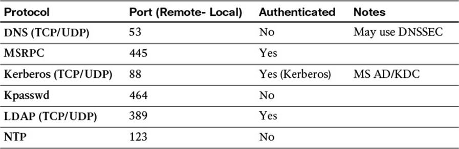
Table 9-2 Active Directory Communication Ports
Note
It is also critical to ensure that good time synchronization is in place before joining Active Directory. Time synchronization issues are the number-one reason ISE fails to join AD.
Joining an Active Directory Domain
The majority of AD join and leave operations occur within the ISE GUI, under Administration > Identity Management > External Identity Sources > Active Directory.
The first procedure is to name the AD domain in the Connection tab and save it, as shown in Figure 9-30. The domain name should be in a DNS style format, such as ciscopress.com or ise.local. After the domain name is saved, the Connection tab will show that the domain has not been joined yet, as displayed in Figure 9-31. For the sake of this book, we’ll retain the default identity store name of “AD1.” This value will be referenced in future chapters as we define the ISE policy.
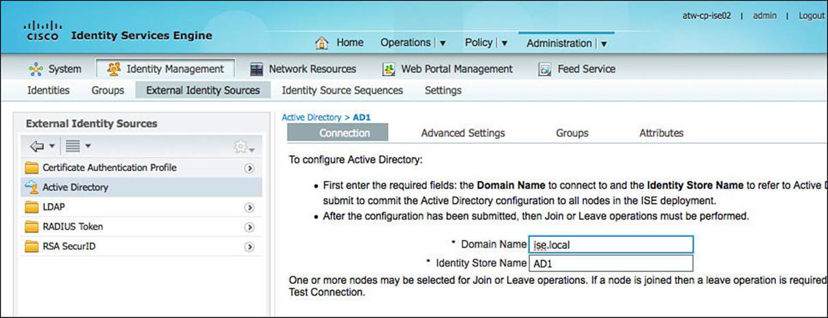
Figure 9-30 Active Directory > Connection tab.
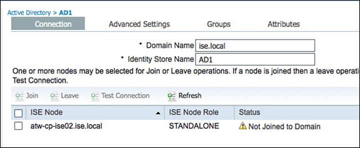
Figure 9-31 Domain not joined.
Although the cConnection tab in Figure 9-30 displays only a single ISE node, the screen will show the status of all ISE nodes in the ISE cube as it pertains to the AD connection(s). In other words, if the ISE deployment (also called the ISE cube) had 34 nodes in it, this tab would display all 34 nodes and the current status of each node’s connection to the configured AD domain. This is necessary because every ISE node will join AD independently of the other nodes, although the entire configuration is handled from this centralized GUI.
Click the Join button, which will open a dialog box for the username and password of an account with the correct rights and permissions to join the machine to AD. Enter the correct username and password and click OK, as shown in Figure 9-32.
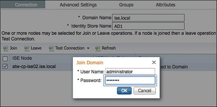
Figure 9-32 Join domain.
Figure 9-33 displays the Connection tab after the ISE node has been joined to the domain.
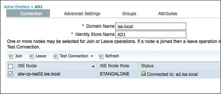
Figure 9-33 Active Directory > Connection tab (after domain join).
Now that ISE has been joined to Active Directory, there are other items that will make the overall deployment easier, such as preselecting the AD groups of interest or even preselecting specific account attributes that will be used in access policy.
To preselect the groups of interest, click the Groups tab from Administration > Identity Management > External Identity Sources > Active Directory. Click Add > Select Groups from Directory, and then the Select Directory Groups pop-up will open, as shown in Figure 9-34. After checking each of the groups of interest, click OK to accept the choices.
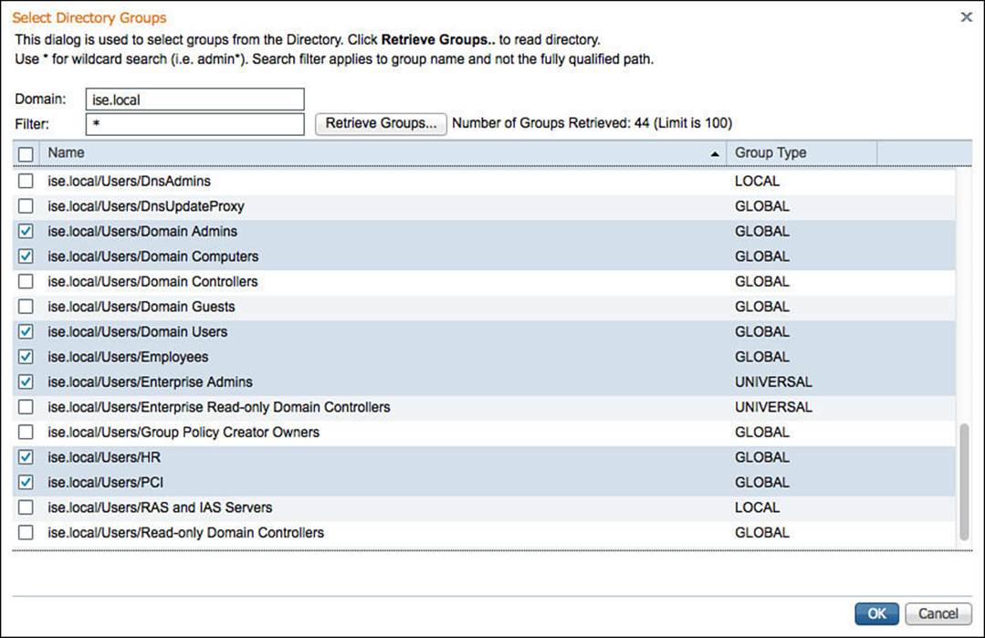
Figure 9-34 Select Directory groups.
Now, when you are building a policy that will use AD group membership as a condition, you will be presented with this list of groups instead of having to sort through the entire list of all AD groups. Figure 9-35 displays the final selection of groups.
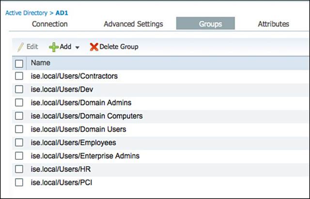
Figure 9-35 Selected Active Directory groups.
In addition to being members of groups, other attributes within Active Directory might be of interest for the creation of access policies. These attributes can be selected in the Attributes tab by clicking Add > Select Attributes from Directory. To make the administration easier, ISE will require the name of a sample user account. Then after you click the Retrieve Attributes button, all attributes of that sample user account will be displayed. Select the attributes of interest, and click. Don’t forget to save the configuration when you are finished.
Figure 9-36 shows attributes being selected, using the employee1 account as the example, and Figure 9-37 displays the final selection of attributes.
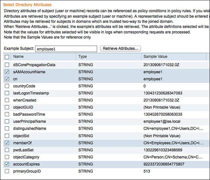
Figure 9-36 Selected Active Directory groups.
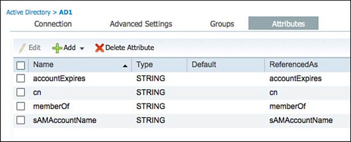
Figure 9-37 Final selection of AD attributes.
In addition to the configuration of the AD Connector, a Test Connection Tool includes both basic and detailed diagnostic tests for the connection. ISE administrators as well as Cisco TAC commonly use this tool to determine theroot cause of any issues with AD communication. Figure 9-38shows the launching of the tool, and Figure 9-39 shows the output of the detailed test results.
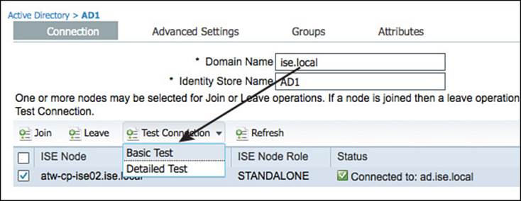
Figure 9-38 Test connection selection.
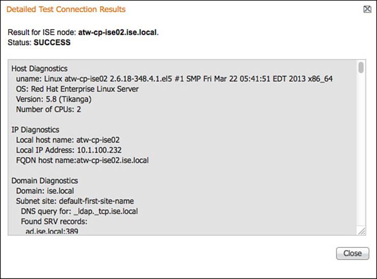
Figure 9-39 Detailed test output.
It’s important to note that AD can be used for authentication as well as authorization. However, it is common to use AD for the authorization operation only, while another source is used for the authentication operation.
Certificate Authentication Profile
As described in the previous section, many identity stores can be used for authentication, not only Active Directory. However, the authorization of the user or device might still require some information that is available in AD or another ID store. The use of digital certificates is one such example.
When you break it down, the authentication of a digital certificate is basically nothing more than ISE validating that the certificate was signed by a trusted authority and the certificate is still valid. However, to perform authorization for the device or user that is being represented by that certificate, ISE can examine values from the certificate and compare those values to attributes that exist in another identity store, such as AD. Therefore, the identity source for certificate-based authentications is a certificate authentication profile (CAP). The CAP tells ISE which value from the certificate should be used as the principle identity for comparison during the authorization phase.
Figure 9-40 shows a common CAP where the certificate subject’s common name (CN) field is being assigned as the principle identity.
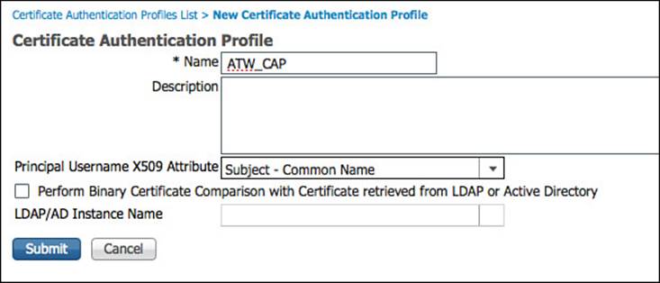
Figure 9-40 Certificate authentication profile.
The second major function of a CAP is to determine whether a binary comparison of the certificate should be performed, and if so, whicht LDAP server to use for that comparison. A binary comparison takes the public certificate used by the user or device attempting access and performs a bit-for-bit comparison to a copy stored elsewhere (usually on the issuing CA itself). This setting is configured within the CAP by checking the Perform Binary Certificate Comparison with Certificate Retrieved from LDAP or Active Directory option and selecting which LDAP or AD store will contain the copies of the public certificates.
Identity Source Sequences
To keep the policies of ISE more flexible and easier to work with, you can create an identity source sequence (ISS). An ISS will check a series of identity sources from top to bottom (as configured), allowing a single authentication rule check a number of identity sources, instead of just one.
ISSes are configured within the ISE GUI under Administration > Identity Management > Identity Source Sequences. With ISE 1.2, three preexisting ISSes are displayed in Figure 9-41 and more can be created as needed.
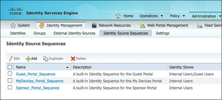
Figure 9-41 Identity source sequences.
To add a new ISS, click Add. Provide a name for the sequence, such as ALL_ID_STORES. As with all objects created within ISE, you should provide a good description to help document the configuration for any other administrators of the system. The description will even help you—in case you have to revisit the configuration after a break, solid descriptions will help you remember why this ISS was created.
A CAP can be selected to include certificate-based authentications, along with the other selected identity stores. Figure 9-42 shows part one of an ISS that will authenticate against a CAP followed by the Internal Users, Guest Users, and finally Active Directory.
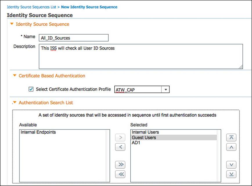
Figure 9-42 All identity stores ISS, part one.
Figure 9-43 shows the second part of the ISS, where the decision on which action to take if a selected identity store cannot be accessed is configured. The ISS can terminate the lookups and trigger a process error, or it can act as if the user was not found and continue to the next identity store in the sequence.
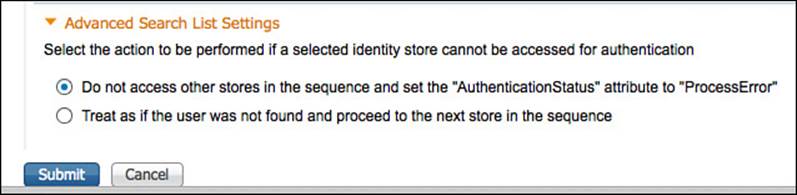
Figure 9-43 All identity stores ISS, part two.
This chapter discussed the initial configuration of ISE and the creation of identity sources for use in authentication policies. The next chapter, Chapter 10, “Authentication Policies,” will detail the use of those identity sources in the authentication policies themselves.
Exam Preparation Tasks
Review All Key Topics
Review the most important topics in the chapter, noted with the key topics icon in the outer margin of the page. Table 9-3 lists a reference of these key topics and the page numbers on which each is found.
Table 9-3 Key Topics for Chapter 9