CCNP Security SISAS 300-208 Official Cert Guide (2015)
Part IV: Implementing Secure Network Access
Chapter 12. Implement Wired and Wireless Authentication
This chapter covers the following exam topics:
![]() Implement Wired/Wireless 802.1X
Implement Wired/Wireless 802.1X
![]() AV Pairs
AV Pairs
![]() Implement MAB
Implement MAB
![]() Implement Network Authorization Enforcement
Implement Network Authorization Enforcement
![]() Troubleshooting, Monitoring, and Reporting Tools
Troubleshooting, Monitoring, and Reporting Tools
In Chapter 9, “Initial Configuration of Cisco ISE,” during the initial configuration of Cisco ISE, you added a network access device (NAD) definition into ISE and were introduced to the concept of importing multiple NADs that are defined in a comma-separated value (CSV) file. In Chapter 10, “Authentication Policies,” and Chapter 11, “Authorization Policies,” some basic authentication and authorization policies were defined on ISE.
What is still missing is one of the most important aspects of secure network access—the configuration of the NADs themselves (switch, wireless controller, and so on), also commonly referred to as the Access Layer device.
The NAD is the point of access for an endpoint and is the first network device through which an endpoint will communicate. This makes it a critical part of any secure network architecture because the NAD is also the main policy enforcement point.
When a company begins the project planning for a secure network access project (most often called a network access control [NAC] project), the basic use cases are always considered, such as how will our corporate assets authenticate to the network and what will be our plan for guest users. A lab might be built, and technology tested with a proof of concept environment (usually at small scale), and things often seem perfect. The proof of concept is considered successful and everyone celebrates the win.
In truth, many important things are not considered until the project team truly starts drilling into the deployment at scale. For instance: How to handle WAN outages when the policy server is centrally located is often considered, but the devil is in the details? What about the desktop reimaging process? In other words, when a corporate workstation needs a software repair, do they use a preexecutable environment (PXE) and boot to the network where a clean image is put onto the workstation? What about using thin-client devices that don’t have a local operating system and that boot to the network and download an operating system (OS) or even connect to a centrally located terminal server?
How will these devices get access to the network if they cannot authenticate, and how does the team ensure these devices can reach the appropriate location to download their OSes or the reimaging server, while restricting access to anything unnecessary? The policy server is obviously a lynch pin to a successful deployment. However, intelligence in the Access Layer device is crucial and will make or break the entire project.
“Do I Know This Already?” Quiz
The “Do I Know This Already?” quiz enables you to assess whether you should read this entire chapter thoroughly or jump to the “Exam Preparation Tasks” section. If you are in doubt about your answers to these questions or your own assessment of your knowledge of the topics, read the entire chapter. Table 12-1 lists the major headings in this chapter and their corresponding “Do I Know This Already?” quiz questions. You can find the answers in Appendix A, “Answers to the ‘Do I Know This Already?’ Quizzes.”
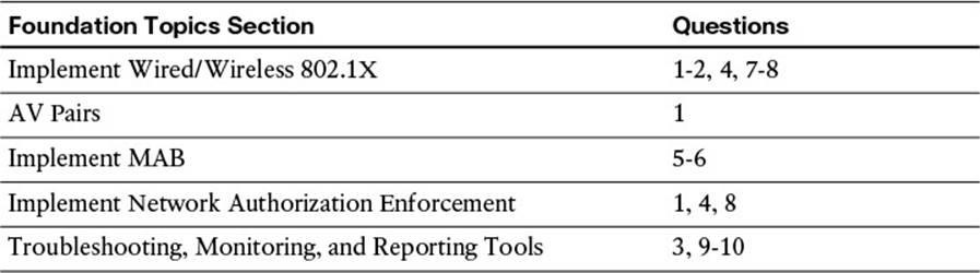
Table 12-1 “Do I Know This Already?” Section-to-Question Mapping
Caution
The goal of self-assessment is to gauge your mastery of the topics in this chapter. If you do not know the answer to a question or are only partially sure of the answer, you should mark that question as wrong for purposes of the self-assessment. Giving yourself credit for an answer you correctly guess skews your self-assessment results and might provide you with a false sense of security.
1. When configuring a Cisco switch for 802.1X, at which level of the configuration do the 802.1X-related commands exist?
a. Global configuration only.
b. Interface configuration only.
c. Both at global configuration level as well as per interface.
d. Enabling 802.1X changes the context to a dot1x subconfiguration mode, where all related commands are entered.
2. When configuring a Cisco Wireless LAN Controller (WLC) for communication with ISE, what must be configured for the wireless LAN (WLAN)? (Choose two.)
a. The authentication and authorization RADIUS servers can be pointed to different ISE PSNs, as long as those PSNs are part of a node group.
b. The authentication and authorization RADIUS servers can be pointed to the same ISE PSN.
c. The WLAN must be configured for SNMP NAC.
d. The WLAN must be configured for RADIUS NAC.
3. True or False? Cisco switches should be configured in production to send syslog messages to the ISE MNT node.
a. True
b. False
4. What is the purpose of adding a user with the username radius-test password password command?
a. The switch can send periodic RADIUS Access-Requests to the AAA servers to verify whether they are still alive. The username and password will be used for that test.
b. The username and password are used for the local RADIUS server available in the switch, which is used in WAN down scenarios.
c. The username and password are used for the supplicant’s outer identity to authenticate against the switch local user database.
d. Without the local username and password in the configuration, an administrator can be locked out of the switch when the RADIUS server is unavailable.
5. True or False? 802.1X can be configured on all switch interfaces, including Layer-3 interfaces.
a. True
b. False
6. Which of the following technologies enables an administrator to maintain the same configuration on all access ports, on all switches, regardless of the type of device connecting to the network?
a. AnyConnect
b. Multi-Auth
c. Flex-Auth
d. Flex-Connect
7. Which host mode will permit a virtually unlimited number of endpoints per port, allowing all subsequent MAC addresses to share the authorization result of the first endpoint authorized?
a. Single Mode
b. MDA
c. Multi-Auth
d. Multi-Host
8. Which interface-level command is the equivalent of “turn authentication on”?
a. authentication port-control auto
b. dot1x system-auth-control
c. ip device-tracking
d. aaa server radius dynamic-author
9. Which command on a Cisco switch will display the current status of the AAA server(s)?
a. show authentication servers
b. show radius servers
c. show aaa servers
d. show ise servers
10. Which command will validate that authentications are being attempted, which authentications are successful, and which authorization results have been assigned?
a. show authentication method dot1x
b. show aaa servers
c. show authentication statistics
d. show authentication session interface <interface>
Foundation Topics
Authentication Configuration on Wired Switches
With Cisco switches, numerous configuration sections will be required. Some aspects must be configured from global configuration mode, and others are configured at the individual interfaces. There is an authentication subsystem that must be enabled across the entire switch (global configuration), and there are interface configurations that must be entered for authentication settings (timers, enabling 802.1X communication, and more).
Global Configuration AAA Commands

By default, the AAA subsystem of the Cisco switch is disabled. Prior to enabling the AAA subsystem, none of the required commands will be available as a configuration option. Here’s how you enable it:
Step 1. Enable Authentication, Authorization, and Accounting on the access switch(es):
C3560X(config)#aaa new-model
An authentication method is required to instruct the switch on which group of RADIUS servers to use for 802.1X authentication requests.
Step 2. Create an authentication method for 802.1X:
C3560X(config)#aaa authentication dot1x default group radius
The method created in Step 2 will enable the user/device identity (username/password or certificate) to be validated by the RADIUS server. However, simply having valid credentials is not enough. There must be an authorization as well. The authorization is what defines that the user or device is actually allowed to access the network and which level of access is actually permitted.
Step 3. Create an authorization method for 802.1X:
C3560X(config)#aaa authorization network default group radius
RADIUS accounting packets are extremely useful and in many cases are required. These types of packets help ensure that the RADIUS server (Cisco ISE) knows the exact state of the switchport and endpoint. Without the accounting packets, Cisco ISE would have knowledge only of the authentication and authorization communication. Accounting packets provide information on when to terminate a live session, as well as local decisions made by the switch (such as AuthFail VLAN assignment, and so on).
RADIUS accounting packets can and should include the framed-ip-address field. That field is populated with the IP address of the endpoint and updates the RADIUS server (ISE) so it has the capability to correlate the MAC address (which it has from the authentication request) to the IP address that is most often dynamically assigned. If the switch supports Device Sensor, the sensor data will be sent to ISE using the RADIUS accounting configuration.
Step 4. Create an accounting method for 802.1X:
C3560X(config)# aaa accounting dot1x default start-stop group radius
Global Configuration RADIUS Commands
A change in the way RADIUS servers are configured in IOS occurred between version 12.2.x and the newer 15.x IOS code. When the configuration differs in the following steps, it will be broken out into a separate section.
IOS 12.2.X
Cisco switches provide a proactive method to check the availability of the RADIUS server. With this practice, the switch will send periodic test authentication messages to the RADIUS server (Cisco ISE). It is looking for a RADIUS response from the server. A success message is not necessary—a failed authentication will suffice because it shows that the server is alive.
If you want to receive an Access-Accept response, the username you are creating here must already exist in either ISE or another identity store, or it needs to be added to the local user database in Cisco ISE at a later step. This account will be used in a later step where you define the RADIUS server:
Step 1. Within global configuration mode, add a username and password for the RADIUS keepalive:
C3560X(config)#username radius-test password password
In Step 2 you are adding each Cisco ISE policy service node (PSN) to the switch configuration, using the test account we created in Step 1. The server will proactively be checked for responses once per hour, in addition to any authentications or authorizations occurring through normal processes. Repeat Step 2 for each PSN.
Step 2. Add the Cisco ISE servers to the RADIUS group:
C3560X(config)#radius-server host ise_ip_address auth-port 1812
acct-port 1813 test username radius-test key shared_secret
The switch has been configured to proactively check the Cisco ISE server for RADIUS responses. Now configure the counters on the switch to determine whether the server is alive or dead. The configuration steps for this do not differ between IOS versions, and they begin in the “Both IOS 12.2.X and 15.X” section.
IOS 15.X
Cisco switches provide a proactive method to check the availability of the RADIUS server. With this practice, the switch will send periodic test authentication messages to the RADIUS server (Cisco ISE). It is looking for a RADIUS response from the server. A success message is not necessary—a failed authentication will suffice because it shows that the server is alive.
If you want to receive an Access-Accept response, the username you are creating here must already exist in either ISE or another identity store, or it needs to be added to the local user database in Cisco ISE at a later step. This account will be used in a later step where you define the RADIUS server:
Step 1. Within global configuration mode, add a username and password for the RADIUS keepalive:
C3560X(config)#username radius-test password password
Next, you are adding each Cisco ISE PSN to the switch configuration.
Step 2. Add the Cisco ISE server:
C3560X(config)#radius server [name]
This is where the configuration really differs between IOS 12.2.X and IOS 15.X. In Step 2, you created a new RADIUS server object. The configuration related to that server is contained within this object. Next, you configure the IP address, ports, and shared secret.
Step 3. Configure the IP address, authentication port, and accounting port:
C3560X(config-radius-server)# address ipv4 [ip-address] auth-port 1812
acct-port 1813
Step 4. Configure the shared secret:
C3560X(config-radius-server)#key [shared-secret]
This uses the test account we created in Step 1. The server will proactively be checked for responses once per hour, in addition to any authentications or authorizations occurring through normal processes. Repeat Step 2 for each PSN.
Step 5. Configure the IP address, authentication port, and accounting port:
C3560X(config-radius-server)# automate-tester username
[username-from-step-1]
Optionally: If you are using a Cisco 3850, 3650, or 5760 series switch, the device sends its calling-station-id in the format of xxxx.xxxx.xxxx by default, instead of xx-xx-xx-xx-xx-xx. This can be changed with the radius-server attribute 31 mac format global configuration command.
Step 6. (Optional) Configure the format for the switch to send the calling-station-id:
3850(config)# radius-server attribute 31 mac format ietf lower-case
Both IOS 12.2.X and 15.X
The switch has been configured to proactively check the Cisco ISE server for RADIUS responses. Now configure the counters on the switch to determine whether the server is alive or dead. Your settings will configure the switch to wait 5 seconds for a response from the RADIUS server and attempt the test 3 times before marking the server dead. If that RADIUS server doesn’t send a valid response within 15 seconds, it will be marked as dead. High availability is covered in more detail in Chapter 21, “ISE Scale and High Availability.” Do the following:
Step 1. Set the dead criteria:
C3560X(config)#radius-server dead-criteria time 5 tries 3
You previously defined the IP address of a RADIUS server to which the switch will send RADIUS messages. However, you must define the servers that are allowed to perform change of authorization (CoA) (RFC 3576 / RFC 5176) operations in a different listing, also within global configuration mode.
Step 2. Enable change of authorization:
C3560X(config)#aaa server radius dynamic-author
C3560X(config-locsvr-da-radius)#client ise_ip_address server-key
shared_secret
Here we configure the switch to send any defined vendor-specific attributes (VSAs) to Cisco ISE PSNs during authentication requests and accounting updates.
Step 3. Configure the switch to use the Cisco vendor-specific attributes:
C3560X(config)#radius-server vsa send authentication
C3560X(config)#radius-server vsa send accounting
The three VSAs you will enable in Step 4 are as follows:
![]() Service-Type (RADIUS attribute 6). This is to ensure that login requests include the Service-Type with them. This Service-Type attribute indicates to ISE which authentication method was chosen for the switchport and, ultimately, the endpoint. The options are
Service-Type (RADIUS attribute 6). This is to ensure that login requests include the Service-Type with them. This Service-Type attribute indicates to ISE which authentication method was chosen for the switchport and, ultimately, the endpoint. The options are
![]() Service-Type:Framed = 802.1X
Service-Type:Framed = 802.1X
![]() Service-Type:Call-Check = MAB
Service-Type:Call-Check = MAB
![]() Service-Type:Login = Local WebAuth
Service-Type:Login = Local WebAuth
![]() Framed-IP-Address (RADIUS attribute 8). This VSA ensures the IP address is included (if one exists). This Framed-IP-Address can be used by ISE to correlate the user with other ISE profiling techniques, which are discussed in detail in Chapter 15, “Profiling.”
Framed-IP-Address (RADIUS attribute 8). This VSA ensures the IP address is included (if one exists). This Framed-IP-Address can be used by ISE to correlate the user with other ISE profiling techniques, which are discussed in detail in Chapter 15, “Profiling.”
![]() Class (RADIUS attribute 25). This VSA should be sent in Access-Request messages. This RADIUS attribute can be used for a number of features, including (NAC and VPN).
Class (RADIUS attribute 25). This VSA should be sent in Access-Request messages. This RADIUS attribute can be used for a number of features, including (NAC and VPN).
Step 4. Next, enable the VSAs:
C3560X(config)#radius-server attribute 6 on-for-login-auth
C3560X(config)#radius-server attribute 8 include-in-access-req
C3560X(config)#radius-server attribute 25 access-request include
Switches can often have multiple IP addresses associated to them. Therefore, it is a best practice to always force any management communications to occur via a specific interface. This interface IP address must match the IP address defined in the Cisco ISE network device object.
The applicable traffic that can be sourced is RADIUS and SNMP. SNMP is optional and used mostly for sending SNMP traps or informs for endpoint profiling.
Step 5. Ensure the switch always sends traffic from the correct interface:
C3560X(config)#ip radius source-interface interface_name
C3560X(config)#snmp-server trap-source interface_name
C3560X(config)#snmp-server source-interface informs interface_name
Global 802.1X Commands
Enabling 802.1X globally on the switch does not actually enable authentication on any of the switchports. Authentication will be configured but not enabled until the interface configuration occurs. Do the following:
Step 1. Enable 802.1X globally on the switch:
C3560X(config)#dot1x system-auth-control
Downloadable access control lists (dACLs) are a common enforcement mechanism in Cisco ISE deployments. For dACLs to function properly on a switch, a function called IP device tracking must be enabled globally. This command allows for the any source in the provided dACL to be replaced with the IP address of the single device connected to the switchport.
Step 2. Enable dACLs to function:
C3560X(config)#ip device tracking
Creating Local Access Control Lists
Certain functions on the switch require the use of locally configured ACLs, such as URL redirection. Some of these ACLs created will be used immediately, and some might not be used until a later phase of your deployment. The goal of this section is to prepare the switches for all possible deployment models at one time and limit the operational expense of repeated switch configuration.
The details of these ACLs and why they are created this way will be discussed in Chapter 13, “Web Authentication,” and Chapter 20, “Deploying Safely.”
Step 1. Add the following ACL to be used on switchports in Monitor Mode:
C3560X(config)#ip access-list extended ACL-ALLOW
C3560X(config-ext-nacl)#permit ip any any
Step 2. Add the following ACL to be used on switchports in Low-Impact Mode:
C3560X(config)#ip access-list ext ACL-DEFAULT
C3560X(config-ext-nacl)#remark DHCP
C3560X(config-ext-nacl)#permit udp any eq bootpc any eq bootps
C3560X(config-ext-nacl)#remark DNS
C3560X(config-ext-nacl)#permit udp any any eq domain
C3560X(config-ext-nacl)#remark Ping
C3560X(config-ext-nacl)#permit icmp any any
C3560X(config-ext-nacl)#remark PXE / TFTP
C3560X(config-ext-nacl)#permit udp any any eq tftp
C3560X(config-ext-nacl)#remark Drop all the rest
C3560X(config-ext-nacl)#deny ip any any log
Step 3. Add the following ACL to be used for URL redirection with web authentication:
C3560X(config)#ip access-list ext ACL-WEBAUTH-REDIRECT
C3560X(config-ext-nacl)#remark explicitly deny DNS from being
redirected to address a bug
C3560X(config-ext-nacl)#deny udp any any eq 53
C3560X(config-ext-nacl)#remark redirect all applicable traffic to the
ISE Server
C3560X(config-ext-nacl)#permit tcp any any eq 80
C3560X(config-ext-nacl)#permit tcp any any eq 443
C3560X(config-ext-nacl)#remark all other traffic will be implicitly
denied from the redirection
Step 4. Add the following ACL to be used for URL redirection with the posture agent:
C3560X(config)#ip access-list ext ACL-AGENT-REDIRECT
C3560X(config-ext-nacl)#remark explicitly deny DNS and DHCP from being
redirected
C3560X(config-ext-nacl)#deny udp any any eq 53 bootps
C3560X(config-ext-nacl)#remark redirect HTTP traffic only
C3560X(config-ext-nacl)#permit tcp any any eq 80
C3560X(config-ext-nacl)#remark all other traffic will be implicitly
denied from the redirection
Interface Configuration Settings for All Cisco Switches
You have just completed the global configuration settings of the access layer switches, including the RADIUS and AAA methods.
This section focuses on building a single port configuration that can be used across your entire secure unified access deployment, regardless of switch type, deployment stage, or deployment model you choose.
Configuring Interfaces as Switchports
One of the first things to do before configuring any of the authentication settings on the switchport is to ensure the switchport is configured as a Layer-2 port, not a Layer-3 port. This command is a simple, one-word command that you will run, and from that point the other commands you enter will all take effect:
Step 1. Enter interface configuration mode for the switchport range:
C3560X(config)#interface range first_interface - last_interface
Step 2. Ensure the ports are Layer-2 switchports:
C3560X(config-if-range)#switchport
The switch has some predefined macros that run a set of commands in order. The host macro automatically runs three commands for you: configuring the port to be an access port (non-trunk), disabling channel groups, and configuring spanning tree to be in portfast mode.
Step 3. Configure the port for Layer-2 edge using the host macro:
C3560X(config-if-range)#switchport host
switchport mode will be set to access
spanning-tree portfast will be enabled
channel group will be disabled
Configuring Flexible Authentication and High Availability
The default behavior of 802.1X is to deny access to the network when an authentication fails. This behavior was discovered to be an undesirable behavior in many customer deployments because it does not allow for guest access, nor does it allow employees to remediate their computer systems and gain full network access. The next phase in handling 802.1X authentication failures was to provide an “Auth-Fail VLAN” to allow a device/user that failed authentication to be granted access to a VLAN that provided limited resources.
This was a step in the right direction, but it was still missing some practicality—especially in environments that must use MAC authentication bypass (MAB) for all the printers and other nonauthenticating devices. With the default behavior of 802.1X, an administrator would have to configure ports for printers and other devices that do not have supplicants differently from the ports where she planned to do authentication.
Therefore, Cisco created flexible authentication (Flex-Auth). Flex-Auth allows a network administrator to set an authentication order and priority on the switchport, thereby allowing the port to attempt 802.1X, MAB, and then WebAuth in order. All these functions are provided while maintaining the same configuration on all access ports, thereby providing a much simpler operational model for customers than traditional 802.1X deployments.
As mentioned previously, there are multiple methods of authentication on a switchport: 802.1X (dot1x), (MAB), and web-based authentication (WebAuth). For the purpose of this wired deployment, we will focus on the first two methods—802.1X and MAB. With 802.1X authentication, the switch sends an identity request (EAP-Identity-Request) periodically after the link state has changed to up. Additionally, the endpoint supplicant should send a periodic EAP over LAN Start (EAPoL-Start) message into the switchport to speed up authentication. If a device is not able to authenticate, it merely has to wait until the dot1x timeout occurs; then MAB occurs. Assuming the device’s MAC address is in the correct database, it is then authorized to access the network. Figure 12-1 illustrates this concept.
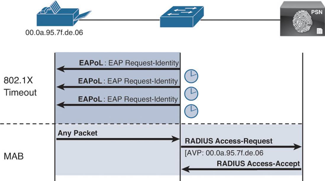
Figure 12-1 Flexible authentication.
The following steps walk you through the configuration of Flex-Auth and the configurable actions for authentication high availability.
With Flex-Auth, you are able to toggle whether dot1x or MAB has the higher priority. The best practice is to always prefer the stronger authentication method (dot1x). The dot1x method is also the default of all Cisco switches. Here’s how:
Step 1. Configure the authentication method priority on the switchports:
C3560X(config-if-range)#authentication priority dot1x mab
In certain deployment methods MAB should occur before 802.1X authentication, such as an environment in which the majority of devices are nonauthenticating. For those corner cases, Flex-Auth does allow for a network administrator to set a user-definable authentication order. However, the best practice is to maintain the order of dot1x and then MAB. Keep in mind that if the order were to be MAB followed by dot1x, with the priority being dot1x followed by MAB, any 802.1X communication would stop the MAB in flight and immediately switch to an 802.1X transaction.
Step 2. Configure the authentication method order on the switchports:
C3560X(config-if-range)#authentication order dot1x mab
Just setting the order and priority alone is not what is actually providing the Flex-Auth technology. You still must enable a key command. This is the command that dictates how the switch should behave when the RADIUS server (Cisco ISE) sends an Access-Reject response. Theauthentication event fail action [action] determines what should occur in the event of an Access-Reject being received.
One option could be to follow the original design of dot1x and deny access to the network. Another option is to assign a VLAN. This is known as using an Auth-Fail VLAN. In the early days of dot1x, this was how guest access was handled. If the authentication failed, you would assign the Guest” VLAN. It’s important to note that in a Cisco ISE secure access deployment, the fail action should be set to next-method. That is the third and final piece of the puzzle to make up the Flex-Auth technology.
Note
If the switch makes a local decision, such as assigning a VLAN instead of denying access, the switch will no longer accept CoA commands from the RADIUS server. A way to think about this is that Cisco ISE now thinks that the switchport is down, but the switch has actually permitted the endpoint to have access to the guest VLAN; therefore, the state is now out of sync.
Step 3. Configure the port to use Flex-Auth:
C3560X(config-if-range)#authentication event fail action next-method
In the global configuration section, you configured the RADIUS server entry to use a test account that will proactively alert the switch when Cisco ISE has stopped responding to RADIUS requests. Now we will configure the switchport to locally authorize the port when that server is found to be dead and reinitialize authentication when the server becomes alive again. The topic of high availability is covered in more detail in Chapter 21.
Step 4. Configure the port to use a local VLAN for voice and data when the RADIUS server is dead (when it stops responding):
C3560X(config-if-range)#authentication event server dead action
authorize
C3560X(config-if-range)#authentication event server dead action
authorize voice
C3560X(config-if-range)#authentication event server alive action
reinitialize
Historically, all authenticated hosts (when the RADIUS server is up) would get full access to network and the others (the new hosts) would not get any access to the network. However, there were concerns regarding multiple authenticating hosts on a single port when a portion of them had already authenticated while the RADIUS server was operational and others (new hosts) were trying to authenticate when the RADIUS server was down.
Cisco added a command called authentication event server dead action reinitialize vlan vlan-id. With this new feature/CLI, when new hosts try to access the network and the RADIUS server is down, that port is reinitialized immediately and all hosts (in this port) get the same VLAN.
Step 5. Configure the port to use a local VLAN when the RADIUS server is dead, and allow existing and new hosts (optional):
C3560X(config-if-range)#authentication event server dead action
reinitialize vlan vlan-id
Host Mode of the Switchport
The default behavior of an 802.1X-enabled port is to authorize only a single MAC address per port. By design, the standard originally relied heavily on the link state of the connection to determine the beginning and ending of the authentication session. Since the inception of 802.1X, enhancements have occurred to allow one or more devices per port. The host modes available are listed here:
![]() Single Host—The default mode of 802.1X is Single Host. Only a single MAC address is permitted per interface. In the early days of 802.1X, the protocol expected to rely on link state for authentication control. When the link comes up, the authenticator (switch) starts sending the EAPoL-ID-Requests to an endpoint. When the link drops, the session is killed and a RADIUS accounting stop message is sent to the RADIUS server.
Single Host—The default mode of 802.1X is Single Host. Only a single MAC address is permitted per interface. In the early days of 802.1X, the protocol expected to rely on link state for authentication control. When the link comes up, the authenticator (switch) starts sending the EAPoL-ID-Requests to an endpoint. When the link drops, the session is killed and a RADIUS accounting stop message is sent to the RADIUS server.
![]() Multidomain Authentication—Multidomain Authentication (MDA) extends 802.1X to support IP telephony by modifying it to understand two separate domains: a data domain and a voice domain. A switchport in MDA mode allows a single MAC address in each domain (that is, one phone and one endpoint behind the phone). It’s important to note that link state cannot be relied on completely because more than one device is on the switchport.
Multidomain Authentication—Multidomain Authentication (MDA) extends 802.1X to support IP telephony by modifying it to understand two separate domains: a data domain and a voice domain. A switchport in MDA mode allows a single MAC address in each domain (that is, one phone and one endpoint behind the phone). It’s important to note that link state cannot be relied on completely because more than one device is on the switchport.
Cisco has enhanced Cisco IP phones to support CDP second port disconnect messages from the phone to the switch. These messages inform the switch of the endpoint unplugging, and to terminate any authentications for that endpoint. This will work for all authentication types (dot1x, MAB, and WebAuth).
The 802.1X standard supports a different method known as EAPoL-Proxy-Logoff. This enables the IP phone to issue a logoff method for the endpoint supplicant that was authenticated behind the phone. However, that only works for dot1x authentications, and not for MAB or WebAuth.
![]() Multiple Authentication—Multiple Authentication (Multi-Auth) is an extension to MDA. It supports the dual-domain solution, while allowing virtually unlimited endpoints to be in the DATA domain. Each endpoint is required to authenticate, and each authentication session on the port is managed separately. The IP phone solutions described in the MDA section are still applicable to Multi-Auth mode.
Multiple Authentication—Multiple Authentication (Multi-Auth) is an extension to MDA. It supports the dual-domain solution, while allowing virtually unlimited endpoints to be in the DATA domain. Each endpoint is required to authenticate, and each authentication session on the port is managed separately. The IP phone solutions described in the MDA section are still applicable to Multi-Auth mode.
![]() Multiple Host—Multiple Host (Multi-Host) mode is not commonly used but is still a valid option. Much like Multi-Auth mode, Multi-Host mode is an extension to MDA. One authentication exists on the voice domain, and one authentication exists on the data domain. All other hosts on the data domain are allowed onto the network using the first successful authentication. It’s an authenticate-one-allow-the-rest type of model. The IP Phone solutions described in the MDA section are still applicable to Mult-Auth mode.
Multiple Host—Multiple Host (Multi-Host) mode is not commonly used but is still a valid option. Much like Multi-Auth mode, Multi-Host mode is an extension to MDA. One authentication exists on the voice domain, and one authentication exists on the data domain. All other hosts on the data domain are allowed onto the network using the first successful authentication. It’s an authenticate-one-allow-the-rest type of model. The IP Phone solutions described in the MDA section are still applicable to Mult-Auth mode.
Note
Using Port Security to limit the number of MAC addresses allowed on a port is not compatible with 802.1X because 802.1X handles this function natively.
During the initial phases of any secure access deployment, it is often desirable to use Multi-Auth mode to ensure that no denial of service occurs while deploying 802.1X. When the deployment moves into an enforcement phase, it is recommended to use MDA mode. In this sample configuration, we are assuming we are in the initial phases of our deployment.
Step 1. Set the host mode of the port:
C3560X(config-if-range)#authentication host-mode multi-auth
When an authentication violation occurs, such as more MAC addresses than are allowed on the port, the default action is to put the port into an err-disabled state. Although this behavior might seem to be a nice and secure behavior, it can create an accidental denial of service, especially during the initial phases of deployment. Therefore, you must set the action to be restrict. This mode of operation enables the first authenticated device to continue with its authorization and deny any additional devices.
Step 2. Configure the violation action:
C3560X(config-if-range)#authentication violation restrict
Configuring Authentication Settings
802.1X is designed to be binary by default. Successful authentication means the user is authorized to access the network. Unsuccessful authentication means the user has no access to the network. This paradigm does not lend itself very well to a modern organization. Most organizations need to do workstation imaging with pre-execution environments (PXEs) or might have some thin clients that have to boot with DHCP and don’t have any way to run a supplicant.
Additionally, when early adopters of 802.1X would deploy authentication companywide, there were repercussions. Many supplicants were misconfigured, and there were unknown devices that could not authenticate because of a lack of supplicant and other reasons.
Cisco created open authentication to aid with deployments. Open authentication allows all traffic to flow through the switchport, even without the port being authorized. This feature enables authentication to be configured across the entire organization but not deny access to any device.
Figure 12-2 depicts the difference between a switchport configured with the default behavior of 802.1X versus a switchport with open authentication configured. This is a key feature that enables the phased approach to deploying authentication, which is discussed in great length in Chapter 20.
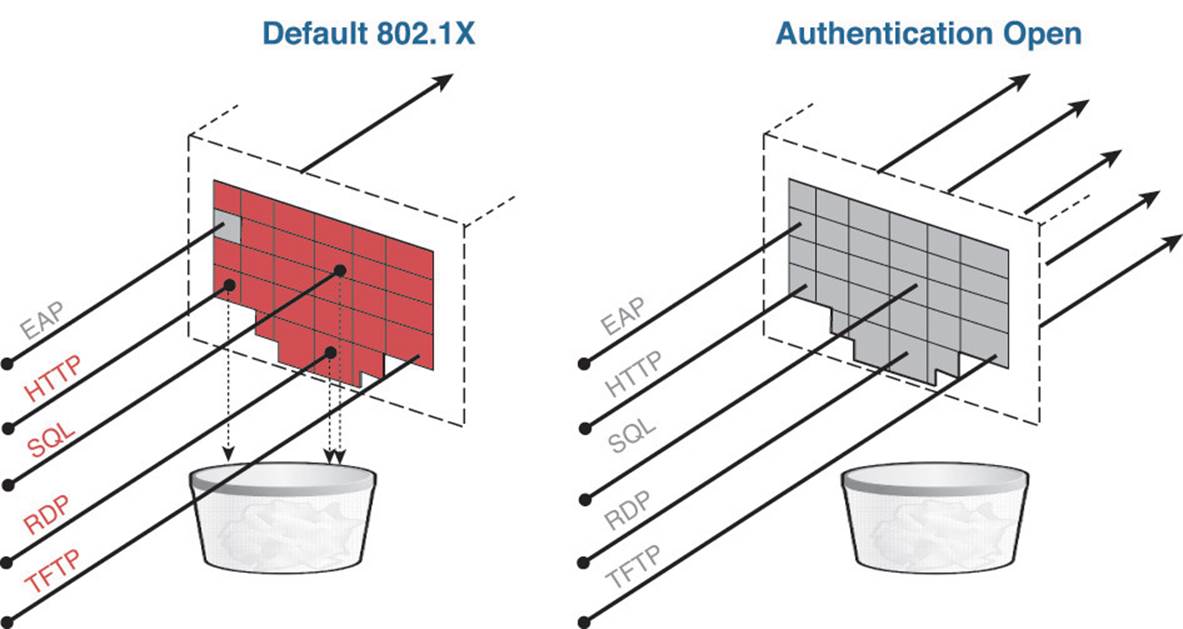
Figure 12-2 Default 802.1X versus authentication open.
Step 1. Set the port for open authentication:
C3560X(config-if-range)#authentication open
Throughout all the discussion in the text, and more specifically this chapter, surrounding MAC authentication bypass, there really is only a single interface command that enables it: mab.
Step 2. Enable MAB on the port:
C3560X(config-if-range)#mab
As previously mentioned, you have enabled dot1x globally on the switch, but no authentication will actually occur yet because the individual switchports have not been configured to do the 802.1X communication. To enable the 802.1X communication to and from a switchport, use the command dot1x pae authenticator.
Step 3. Enable the port to perform IEEE 802.1X authentication:
C3560X(config-if-range)#dot1x pae authenticator
Even with all the configuration commands that have been entered into the switch so far, you will still not be processing any authentication requests yet. A key command at the end of the switch configuration section is required first.
Configuring Authentication Timers
Many timers can be modified as needed in a deployment. Unless you are experiencing a specific problem where the adjusting of a timer can correct some unwanted behavior, it is recommended to leave all timers at their default values except for the 802.1X transmit timer (tx-period).
The tx-period timer defaults to a value of 30 seconds. Leaving this value at 30 seconds provides a default wait of 90 seconds (3 × tx-period) before a switchport begins the next method of authentication and begins the MAB process for nonauthenticating devices.
Based on numerous deployment experiences, the recommendation is that you set the tx-period value to 10 seconds to provide the most optimal time for MAB devices. Setting the value below 10 seconds can result in unwanted behavior; setting the value greater than 10 seconds can result in DHCP timeouts.
Step 1. Configure the tx-period timer:
C3560X(config-if-range)#dot1x timeout tx-period 10
The recommendation of 10 seconds might need to be reduced or increased, depending on the needs of your specific deployment. However, 10 seconds has been a successful timer for a vast majority of deployments.
Applying the Initial ACL to the Port and Enabling Authentication
This step prepares the port for Monitor Mode by applying a default ACL on the port without denying any traffic.
Step 1. Apply the initial ACL (ACL-ALLOW):
C3560X(config-if-range)#ip access-group ACL-ALLOW in
If you want to enable authentication now, you can. A key interface command is needed to truly enable all these authentication commands: authentication port-control auto. Without this command, everything will appear to be working but no authentications will be sent to the RADIUS server.
Step 2. Turn on authentication:
C3560X(config-if-range)#authentication port-control auto
You have three options for the port-control command, detailed here:
![]() auto—Enables authentication on this port and allows the authorization result to be sent from the RADIUS server. Short answer: “Turn authentication on!”
auto—Enables authentication on this port and allows the authorization result to be sent from the RADIUS server. Short answer: “Turn authentication on!”
![]() force-authorized—Hard-codes the port to be in an authorized state. This basically disables the process of authentication but allows all endpoints to connect to the network. Short answer: “Allow all endpoints connected to this switchport.”
force-authorized—Hard-codes the port to be in an authorized state. This basically disables the process of authentication but allows all endpoints to connect to the network. Short answer: “Allow all endpoints connected to this switchport.”
![]() force-unauthorized—Hard-codes the port to be in an unauthorized state. This basically disables the process of authentication and denies network access to all endpoints. Short answer: “Denial of service (DoS) the endpoints connected to this switchport.”
force-unauthorized—Hard-codes the port to be in an unauthorized state. This basically disables the process of authentication and denies network access to all endpoints. Short answer: “Denial of service (DoS) the endpoints connected to this switchport.”
Authentication Configuration on WLCs
This section reviews the configuration for the Cisco wireless LAN controller. It focuses on version 7.3 and above. With each version of the WLC software, new features are released to aid in BYOD solutions, such as DNS-based ACLs in version 7.6. All WLC screenshots in this chapter are from WLC version 7.6.
As with the Cisco catalyst switches, this chapter assumes you have established basic connectivity with the NAD and are now to the point of bootstrapping the WLC for use with ISE. Similarly, some configuration is globally applicable, meaning it applies to the entire system. Other configuration is per-wireless LAN (per-SSID), which is comparable to interface configurations on the wired NADs.
Configuring the AAA Servers
Much like the wired NADs, the first procedure in configuring the WLC is to add the ISE policy service nodes (PSNs) to the WLC as RADIUS authentication and accounting servers. This is a configuration that affects the entire WLC as a system, similar to the global configuration with a switch.
Adding the RADIUS Authentication Servers
The WLC separates the AAA server configuration into two sections. The authentication servers are configured in a separate section from the accounting servers. Start by adding the ISE PSN to the authentication servers. From the WLC GUI, do the following:
Step 1. Navigate to Security > RADIUS > Authentication.
You need to ensure that the endpoint’s MAC address is populated in the RADIUS calling-station-id field in all RADIUS packets and that a hyphen is used for the delimiter. This is important because Cisco ISE uses the endpoint MAC address as the unique identifier for the endpoint’s identity. This is used for with both 802.1X authentications and wireless MAB.
Step 2. Ensure that both the Acct Call Station ID Type and Auth Call Station ID Type drop-down boxes are set to System MAC Address.
Step 3. Ensure that the MAC Delimiter is set to Hyphen.
Figure 12-3 shows the final configuration for the Call Station ID and MAC Delimiter settings.
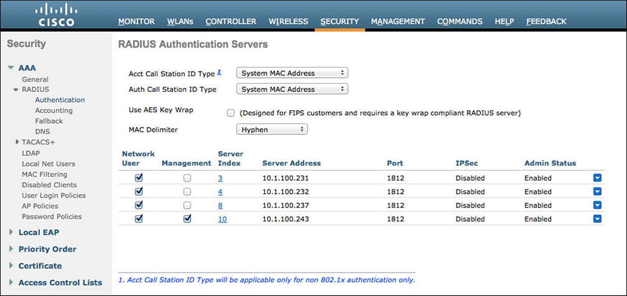
Figure 12-3 Security > RADIUS > Authentication.
Step 4. Click New to add the ISE PSN.
Step 5. Enter the IP address of the PSN (or the VIP, if using a load balancer).
Step 6. Fill in the Shared Secret field. This must match what is configured in the ISE network device object.
Step 7. The port must be 1812 for authentication.
Step 8. Ensure the server is enabled.
Step 9. Ensure that RFC 3576 (CoA) is enabled.
Step 10. Set the default server timeout to 2 seconds.
Step 11. Ensure network user is enabled. This is simply stating that the RADIUS server can be used for network authentications.
Step 12. Click Apply in the upper-right corner.
Step 13. Save the configuration.
Figure 12-4 shows a completed server configuration.
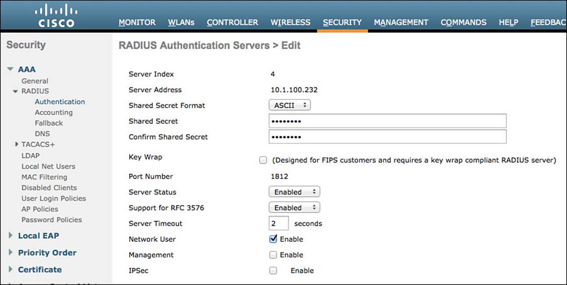
Figure 12-4 Completed server configuration.
Repeat these steps for each PSN you need to add.
Adding the RADIUS Accounting Servers
As mentioned previously, the WLC separates the AAA server configuration into two sections. Now we will define the ISE PSN in the accounting server section (see Figure 12-5). From the WLC GUI, follow these steps:
Step 1. Navigate to Security > RADIUS > Accounting.
Step 2. Ensure the MAC Delimiter is set to Hyphen.
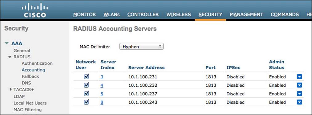
Figure 12-5 RADIUS accounting servers.
Step 3. Click New to add the ISE PSN.
Step 4. Enter the IP address of the PSN.
Step 5. Enter the shared secret to match what is configured on ISE.
Step 6. Ensure the port is 1813.
Step 7. Ensure the server is enabled.
Step 8. Verify that the Network User check box is enabled.
Figure 12-6 shows a completed server entry.
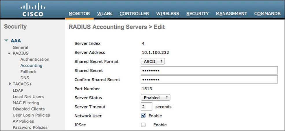
Figure 12-6 Completed accounting server configuration.
Step 9. Click Apply in the upper-right corner.
Step 10. Save the configuration.
Repeat these steps for each PSN you need to add.
Configuring RADIUS Fallback (High-Availability)
The primary RADIUS server (the server with the lowest server index) is assumed to be the most preferable server for the Cisco WLC. If the primary server becomes unresponsive, the controller switches to the next active server (the server with the next lowest server index). The controller continues to use this backup server unless you configure the controller to fall back to either the primary RADIUS server when it recovers and becomes responsive or a more preferable server from the available backup servers.
From the WLC GUI, do the following:
Step 1. Navigate to Security > AAA > RADIUS > Fallback.
Step 2. Set the Fallback Mode to Active.
Selecting Active causes the Cisco WLC to revert to a server with a lower priority from the available backup servers by using RADIUS probe messages to proactively determine whether a server that has been marked inactive is back online.
Step 3. For the Username, enter the name to be sent in the inactive server probes.
We have been using radius-test as the username so far in the book. It’s important to note, though, that you do not need to enter a password for this test user account because the system will simply look for a response from the RADIUS server; pass or fail does not matter.
Step 4. Enter a value for the Interval in Sec field.
The interval states the inactive time in passive mode and probe interval in active mode. The valid range is 180–3600 seconds, and the default value is 300 seconds. Figure 12-7 shows the completed RADIUS fallback settings.
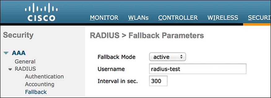
Figure 12-7 RADIUS fallback settings.
Configuring the Airespace ACLs
Just as we did with the Cisco catalyst switches, we will prestage the WLC with some access lists for:
![]() A web authentication ACL (ACL-WEBAUTH-REDIRECT)
A web authentication ACL (ACL-WEBAUTH-REDIRECT)
![]() Posture agent redirection (ACL-AGENT-REDIRECT)
Posture agent redirection (ACL-AGENT-REDIRECT)
Notice that we are using the same ACL names as the Cisco switches. This is not required, but we do it this way to ensure consistency where possible.
Creating the Web Authentication Redirection ACL
As with the catalyst switches, we will need a local ACL on the wireless controller that will redirect web traffic to the centralized web authentication portal. However, with the catalyst switch, a permit statement means that the traffic should be redirected and a deny statement describes traffic that should not be redirected. With the switch, you need two ACLs: one to define what gets redirected and a second one to filter traffic (permit or deny traffic flow).
With the Cisco WLC, there is a single access list, and it pulls double duty. It permits and denies traffic flow; at the same time, though, the traffic that is denied is redirected to the centralized web authentication portal.
From the WLC GUI, do the following:
Step 1. Navigate to Security > Access Control Lists > Access Control Lists.
Step 2. Click New to add a new ACL (see Figure 12-8).
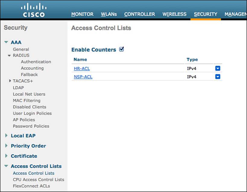
Figure 12-8 ACLs.
Step 3. Fill in the name ACL-WEBAUTH-REDIRECT (see Figure 12-9).
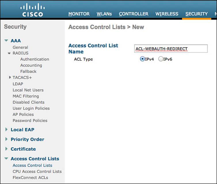
Figure 12-9 Naming the ACL.
Step 4. Click Apply.
You will be returned to the main access list screen.
Step 5. Click the new entry, ACL-WEBAUTH-REDIRECT, as shown in Figure 12-10.
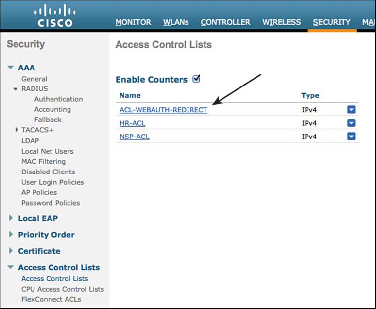
Figure 12-10 Listing of ACLs.
Step 6. Click Add New Rule in the upper-right corner.
A rule in the WLC is the equivalent of an access control entry in the switch. It is a line in the access list.
Step 7. You need to create a set of rules for this ACL that does the following:
![]() Permits all traffic outbound (toward the client)
Permits all traffic outbound (toward the client)
![]() Permits DHCP and DNS inbound
Permits DHCP and DNS inbound
![]() Permits TCP port 8443 to the ISE servers
Permits TCP port 8443 to the ISE servers
![]() Denies all other traffic, which will redirect the rest
Denies all other traffic, which will redirect the rest
Figure 12-11 shows an example of a completed ACL.
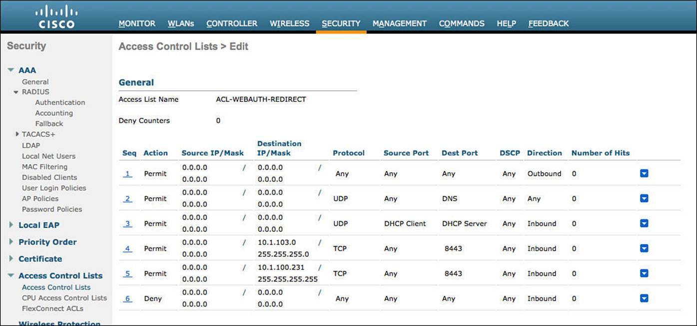
Figure 12-11 ACL-WEBAUTH-REDIRECT example.
Creating the Posture Agent Redirection ACL
Just as with the web authentication traffic, you should have an ACL for posture assessments. When a client successfully authenticates to the network but their posture is not known, the resulting authorization should be to put the client in a Posture_Req state on the controller and use a URL-Redirection with an ACL to redirect traffic to ISE, just like with web authentication.
The difference here is that we must open some more ports to allow even more traffic to flow than with web authentication. Technically, there is nothing to prevent you from using a single ACL for both web authentication and posture agent redirection if you are willing to open up all that traffic in both use cases.
To maintain consistency throughout our deployment examples, we will create a separate ACL here.
From the WLC GUI, do the following:
Step 1. Navigate to Security > Access Control Lists > Access Control Lists.
Step 2. Click New to add a new ACL.
Step 3. Enter the name ACL-AGENT-REDIRECT.
Step 4. Click Apply.
Step 5. Click the new entry: ACL-AGENT-REDIRECT.
Step 6. Click Add New Rule in the upper-right corner.
Step 7. Build a rule set for this ACL that accomplishes the following:
![]() Permits all traffic outbound (toward the client)
Permits all traffic outbound (toward the client)
![]() Permits DHCP and DNS inbound
Permits DHCP and DNS inbound
![]() Permits TCP port 8443 to the ISE servers
Permits TCP port 8443 to the ISE servers
![]() Permits TCP and UDP Port 8905 and 8909 to the ISE servers
Permits TCP and UDP Port 8905 and 8909 to the ISE servers
![]() Permits applicable traffic to the remediation servers (the servers that will fix the client if it fails the posture assessment; could be patch management systems or even external websites)
Permits applicable traffic to the remediation servers (the servers that will fix the client if it fails the posture assessment; could be patch management systems or even external websites)
![]() Denies all other traffic, which will redirect the rest
Denies all other traffic, which will redirect the rest
Figure 12-12 shows an example of a completed ACL
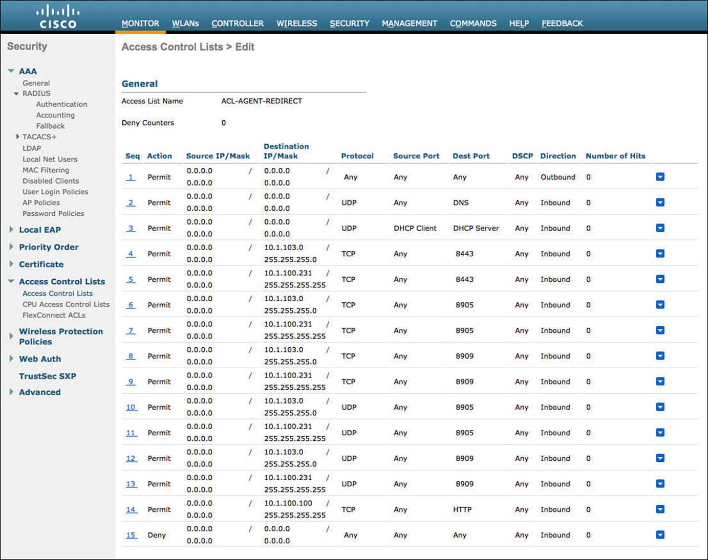
Figure 12-12 ACL-AGENT-REDIRECT example.
Creating the Dynamic Interfaces for the Client VLANs
When you want to assign a user or device to a VLAN on a catalyst switch, you simply assign the VLAN to the port, and the entire switch port is then assigned to that particular VLAN.
The wireless controller has only a few physical connections to the wired network, and it must bridge all wireless users from their RF networks (Wi-Fi) to the physical wired network. It also must have the capability to assign different VLANs per authenticated session (if necessary). I know, you’re thinking it just needs to be connected with a trunk, right? Well, yes, that’s true.
The WLC will be configured to use 802.1Q to tag traffic for a specific VLAN as that traffic exits the controller. However, the controller will call this a dynamic interface because of the way it can assign a physical interface to traffic or assign a tag.
We will create two dynamic interfaces in this chapter—one for employee traffic and one for guest traffic.
Creating the Employee Dynamic Interface
This interface is used for all successful authentications to the corporate wireless LAN, providing full access to the entire network.
From the WLC GUI, do the folowing:
Step 1. Navigate to Controller > Interfaces.
Step 2. Click New.
Step 3. Name your Interface. We will use the name employee in our example.
Step 4. Provide the VLAN ID to be used in the 802.1Q tag.
Step 5. Click Apply.
Step 6. Click the new interface named employee.
Step 7. You will most likely leave the settings alone until you reach the physical information section.
Step 8. Provide an IP address, netmask, and gateway for the VLAN.
Step 9. Provide the DHCP server address.
Step 10. Click Apply.
Figure 12-13 shows a sample employee dynamic interface configuration.
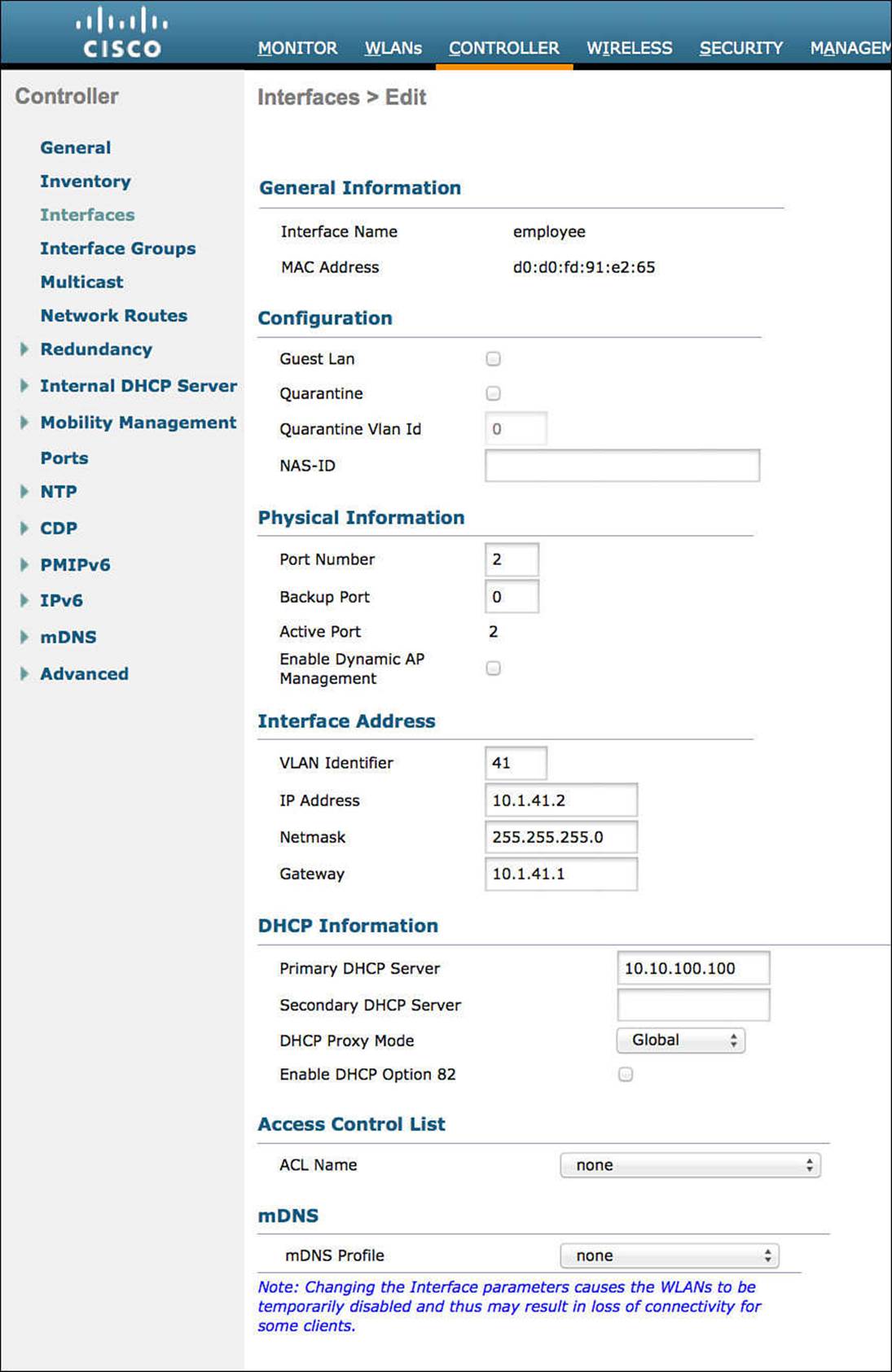
Figure 12-13 Employee dynamic interface.
Creating the Guest Dynamic Interface
This interface is used for all devices connecting to the GUEST WLAN, as well as unsuccessful or unauthorized authentications to the corporate wireless LAN. This interface will have Internet access only.
From the WLC GUI, do the folowing:
Step 1. Navigate to Controller > Interfaces.
Step 2. Click New.
Step 3. Name your Interface. We will use the name guest in our example.
Step 4. Provide the VLAN ID to be used in the 802.1Q tag.
Step 5. Click Apply.
Step 6. Click the new interface named employee.
Step 7. You will most likely leave the settings alone until you reach the physical information section.
There is a Guest LAN check box—do not enable it. This is not for GUEST WLANs; it is for providing guest access to directly connected wired LANs.
Step 8. Enter an IP address, netmask, and gateway for the VLAN.
Step 9. Enter the DHCP server address.
Step 10. Click Apply.
Figure 12-14 shows a sample guest dynamic interface configuration.
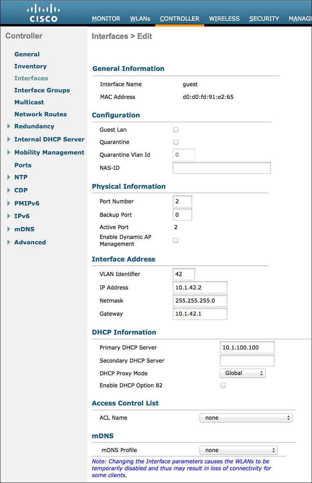
Figure 12-14 Guest dynamic interface.
Creating the Wireless LANs
Now that the RADIUS servers, ACLs, and dynamic interfaces are all created and configured, we will move on to creating two WLANs: a guest WLAN and a corporate WLAN. The guest WLAN will be an open WLAN, whereas the corporate WLAN will be configured to use 802.1X to authenticate devices.
Creating the Guest WLAN
The guest WLAN will be created as an open SSID but will send the endpoint MAC addresses to ISE for MAB, just like the wired networks.
From the WLC GUI, follow these steps (see Figure 12-15):
Step 1. Using the headers across the top, navigate to WLAN.
Step 2. Select Create New in the drop-down menu.
Step 3. Click Go.
Step 4. Select WLAN.
Step 5. Give the WLAN profile a name; we will use CP-Guest in this example.
Step 6. Enter an SSID name; we will use CiscoPress-Guest in this example.
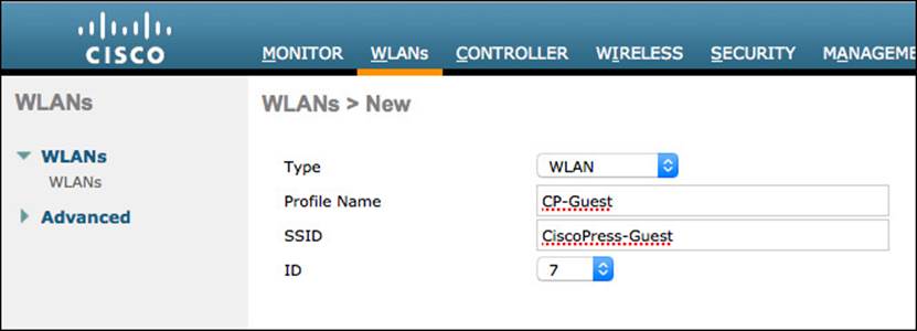
Figure 12-15 Guest WLAN creation.
Note
WLAN ID is a unique identifier for each WLAN/SSID on a controller. The default should be fine in most cases. However, the WLAN ID can be used as a condition within your authorization policy. If you choose to use the WLAN ID in your policy, ensure that the WLAN ID is the same across all WLCs; otherwise, you might get unwanted results.
Step 7. Click Apply.
General Tab
The General tab is where a WLAN is enabled or disabled, and it is where the default interface is selected:
Step 1. If you are ready to put this SSID in an operative state, ensure the Enabled check box is selected.
Step 2. Next to Interface/Interface Group (G), select the GUEST interface we created previously from the drop-down menu. Figure 12-16 shows the General tab.
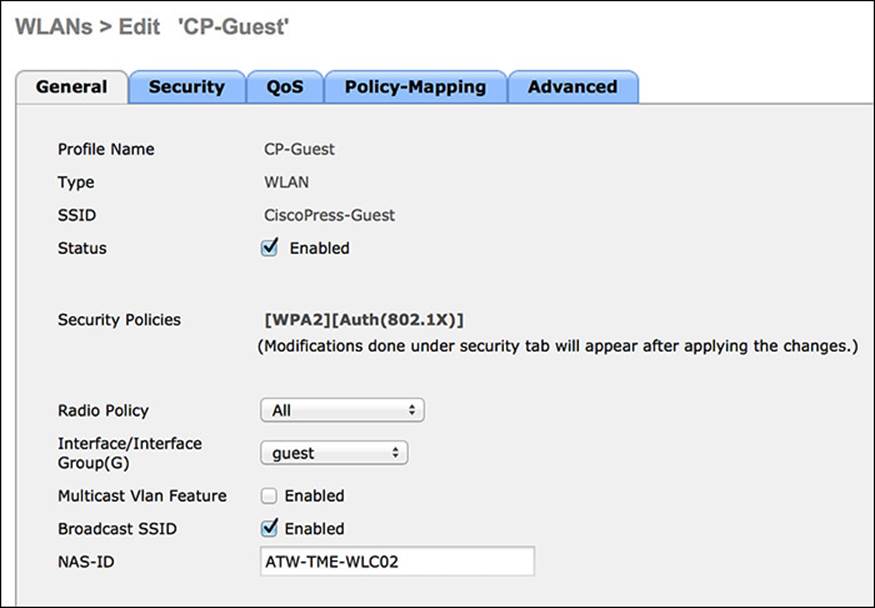
Figure 12-16 GUEST WLAN General tab.
Step 3. Click the Security tab.
Layer 2 Security Tab
The Layer 2 Security tab relates to the manner of protection for which devices associate to the wireless network and what encryption should be used (if any). It defines the use of Wi-Fi protected access (WPA), wired equivalent privacy (WEP), or even the ability to do MAC filtering. For an open guest network, you will select no Layer-2 security and will enable MAC filtering, which is how you configure wireless MAB. Here’s how:
Step 1. Change the Layer 2 Security from the default (WPA) to None.
Step 2. Check the box for MAC Filtering (which is MAB). Figure 12-17 shows the completed tab.
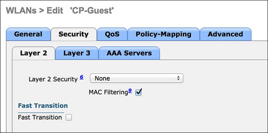
Figure 12-17 Layer 2 Security tab.
Step 3. Click the Layer 3 tab.
Layer 3 Security Tab
The Layer-3 security options are used for local web authentication and should be set to None for an ISE deployment with centralized web authentication:
Step 1. Ensure the Layer-3 security option is set to None, as shown in Figure 12-18.
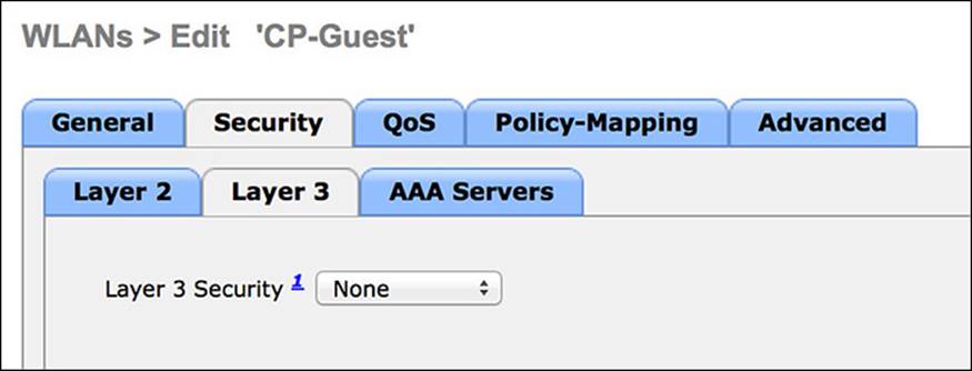
Figure 12-18 Layer 3 Security tab.
Step 2. Click the AAA Servers tab.
AAA Servers Tab
For the Cisco WLC to work correctly for all ISE services, the authentication and accounting servers must be set identically. While the GUI of the WLC permits them to be set for differing servers, that will break certain functionality related to ISE services:
Step 1. Select your ISE PSN(s) for both authentication and accounting.
Step 2. Click Apply. Figure 12-19 shows the completed tab.
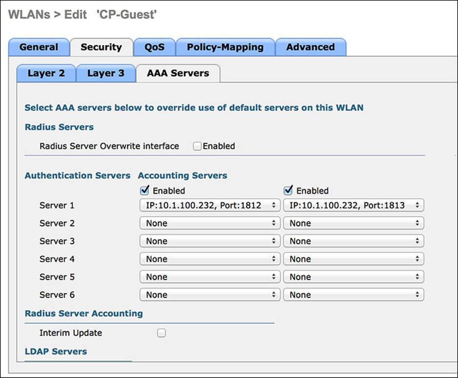
Figure 12-19 AAA Servers tab.
Step 3. Click the Advanced tab.
Advanced Tab
To allow ISE to override the assigned VLAN, interface, or even to assign an ACL, the Allow AAA Override setting must be enabled:
Step 1. Enable Allow AAA Override.
The WLC has built-in capabilities for the profiling of endpoints and sending that profiling data to ISE. The DHCP Addr. Assignment check box must be enabled for the DHCP Device Sensor built in to the WLC to function correctly.
Step 2. Check the box for DHCP Addr. Assignment.
A NAC State setting is available on the Advanced tab. This setting is critical to allow for URL redirection, centralized web authentication, posture assessment, native supplicant provisioning, and more. This is a critical setting for the interaction of ISE with the WLC.
Step 3. Change the NAC State to RADIUS NAC.
Step 4. Scroll down and enable both the DHCP and HTTP RADIUS Client Profiling options. This is revisited in Chapter 15, “Profiling,” where endpoint profiling is covered in detail.
Step 5. Click Apply.
Step 6. Save the configuration.
Figures 12-20 and 12-21 display the completed Advanced tab.
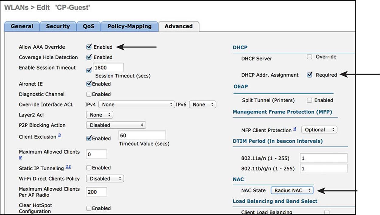
Figure 12-20 Advanced Tab part 1.
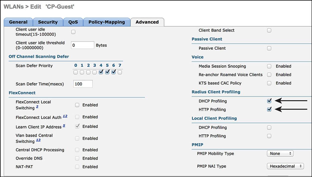
Figure 12-21 Advanced Tab part 2.
Creating the Corporate SSID
The corporate WLAN will be created as a closed SSID and will require 802.1X authentication for an endpoint to associate to the WLAN. Unlike wired networks, wireless networks have the added benefit of truly rejecting all access without a successful authentication. Users are attuned to the requirement of configuring software to connect to a wired network. The same is very much not true when it comes to wired networks.
From the WLC GUI, do the following:
Step 1. Navigate to WLAN.
Step 2. Select Create New.
Step 3. Click Go.
Step 4. Select WLAN.
Step 5. Give the WLAN profile a name; we will use CiscoPress in this example.
Step 6. Enter an SSID name; we will use CiscoPress in this example.
Step 7. Click Apply.
Figure 12-22 shows the new WLAN being added.
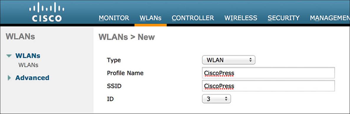
Figure 12-22 CiscoPress WLAN.
General Tab
Step 1. If you are ready to put this SSID into an operative state, ensure the Enabled check box is selected.
Step 2. Next to the Interface/Interface Group (G), select the employee interface we created previously from the drop-down.
Step 3. Click the Security tab.
Figure 12-23 shows the final General tab.
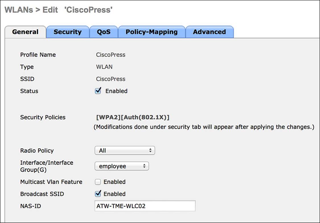
Figure 12-23 General tab.
Layer 2 Security Tab
The Layer 2 Security tab relates to the manner of protection for which devices associate to the wireless network and what encryption should be used (if any). It defines the use of WPA, WEP, or even the ability to perform MAC filtering. Do the following:
Step 1. The default setting of WPA+WPA2 is correct.
Step 2. You will not be enabling MAC filtering.
Step 3. Ensure that 802.1X is checked for Authentication Key Management.
Figure 12-24 shows the final Layer 2 Security tab.
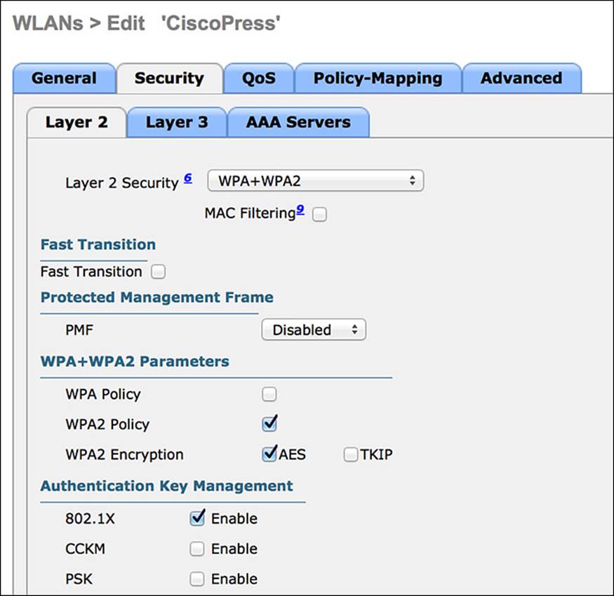
Figure 12-24 Layer 2 Security tab.
Step 4. Click the Layer 3 tab.
Layer 3 Security Tab
Step 5. Ensure the Layer 3 security is set to “None” (see Figure 12-25).
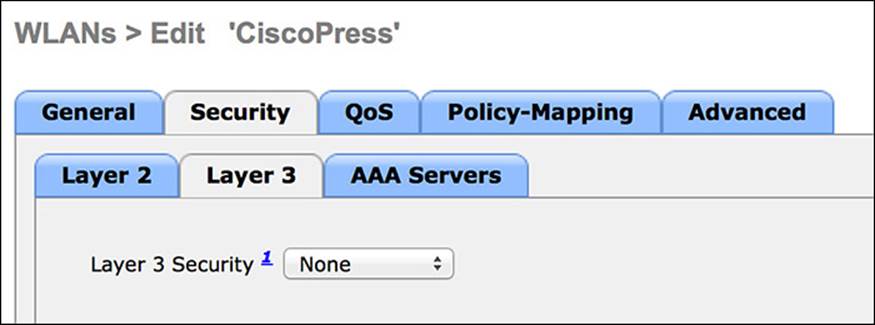
Figure 12-25 Layer 3 Security tab.
Step 6. Click the AAA Servers tab.
AAA Servers Tab
For the Cisco WLC to work correctly for all ISE services, the authentication and accounting servers must be set identically. Although the GUI of the WLC permits them to be set for differing servers, that will break certain functionality related to ISE services:
Step 1. Select your ISE PSN(s) for both authentication and accounting (see Figure 12-26).
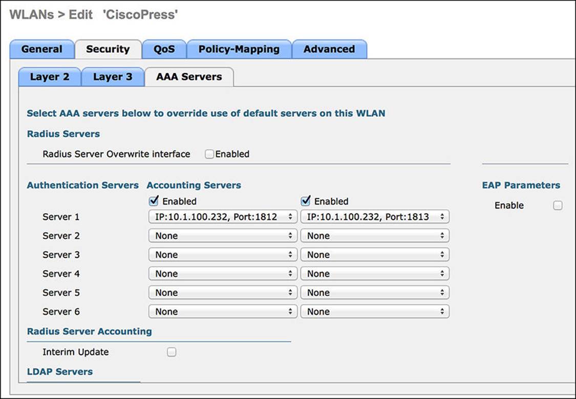
Figure 12-26 AAA Servers tab.
Step 2. Click Apply.
Step 3. Click the Advanced tab.
Advanced Tab
To allow ISE to override the assigned VLAN or interface, or even to assign an ACL, the Allow AAA Override setting must be enabled:
Step 1. Enable Allow AAA Override.
The WLC has built-in capabilities for the profiling of endpoints and sending that profiling data to ISE. The DHCP Addr. Assignment check box will need to be enabled for the DHCP device sensor built in to the WLC to function correctly.
Step 2. Check the box for DHCP Addr. Assignment.
A NAC State setting exists on the Advanced tab. This setting is critical to allow for URL redirection, centralized web authentication, posture assessment, native supplicant provisioning, and more. This is a critical setting for the interaction of ISE with the WLC.
Step 3. Change the NAC State to RADIUS NAC.
Step 4. Scroll down and enable both the DHCP and HTTP RADIUS Client Profiling options. This is revisited in Chapter 15, where endpoint profiling is covered in detail.
Step 5. Click Apply.
Step 6. Save the configuration.
Step 7. Figures 12-27 and 12-28 display the completed Advanced tab.
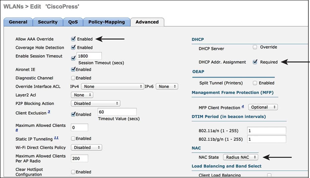
Figure 12-27 Advanced Tab part 1.
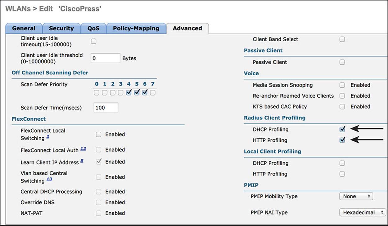
Figure 12-28 Advanced Tab part 2.
Verifying Dot1X and MAB
There are numerous ways to verify the authentication operations of switches and wireless controllers. Three locations always must be examined to validate a complete end-to-end transaction. Two of those three locations are much more common and easy to use. The three locations are:
![]() Endpoint supplicant—For 802.1X authentications
Endpoint supplicant—For 802.1X authentications
![]() Network access device—For all authentications
Network access device—For all authentications
![]() Cisco ISE—For all authentications
Cisco ISE—For all authentications
Endpoint Supplicant Verification
Verifying the authentications from the supplicant is a bit outside of the exam blueprint, so this book will not focus on it much. With Cisco AnyConnect NAM as your supplicant, you can use the DART tool to get a detailed communication, even perform packet captures at the endpoint. If the supplicant is an Apple supplicant (MAC-OSX or iOS), you must use the Apple iPhone Configuration Utility to extract and examine the supplicant logs.
With Windows, no supplicant logging is on by default. You must use the command-line netsh ras set tracing * enable to enable the supplicant’s logging capabilities. Once enabled, the logs are added to the %systemroot%\tracing folder.
Network Access Device Verification
Two NADs are focused on here: Cisco switches and Cisco wireless LAN controllers. Each is quite different in how authentications are verified and will therefore be discussed in two separate sections.
Verifying Authentications with Cisco Switches
Many items can be tested with a Cisco switch, with many tools being provided in Cisco IOS. The ones used most often are described in this section.
show AAA servers Command
One of the first things to check with a Cisco switch is the status of the RADIUS server (ISE). The show aaa servers command is a quick and simple way to see the current status of the ISE server from the switch’s perspective. Example 12-1 shows the use of this command and its output. The main item of interest with this command’s output is the State field. In Example 12-1, the current state is UP. Use this command to validate that the server is up. If it is down, communication to the RADIUS server will not occur.
Example 12-1 show aaa servers Command
3750-X#sho aaa servers
RADIUS: id 1, priority 1, host 10.1.100.232, auth-port 1812, acct-port 1813
State: current UP, duration 93974s, previous duration 0s
Dead: total time 0s, count 0
Quarantined: No
Authen: request 29, timeouts 0, failover 0, retransmission 0
Response: accept 28, reject 0, challenge 0
Response: unexpected 0, server error 0, incorrect 0, time 247795ms
Transaction: success 29, failure 0
Throttled: transaction 0, timeout 0, failure 0
Author: request 0, timeouts 0, failover 0, retransmission 0
Response: accept 0, reject 0, challenge 0
Response: unexpected 0, server error 0, incorrect 0, time 0ms
Transaction: success 0, failure 0
Throttled: transaction 0, timeout 0, failure 0
Account: request 35, timeouts 0, failover 0, retransmission 0
Request: start 4, interim 4, stop 1
Response: start 4, interim 4, stop 1
Response: unexpected 0, server error 0, incorrect 0, time 16ms
Transaction: success 35, failure 0
Throttled: transaction 0, timeout 0, failure 0
Elapsed time since counters last cleared: 1d2h6m
Estimated Outstanding Access Transactions: 0
Estimated Outstanding Accounting Transactions: 0
Estimated Throttled Access Transactions: 0
Estimated Throttled Accounting Transactions: 0
Maximum Throttled Transactions: access 0, accounting 0
Requests per minute past 24 hours:
high - 2 hours, 15 minutes ago: 3
low - 2 hours, 6 minutes ago: 0
average: 0
3750-X#
test AAA Command
Cisco switches have a built-in mechanism to send test authentications to the AAA servers they are configured to use. Using the test aaa command, you can verify that an authentication is successfully sent to and received by the RADIUS server. Example 12-2 shows the use of the test aaacommand and the successful response. The test command will send an authentication request using PAP_ASCII and return a RADIUS Access-Accept if successful or an Access-Reject if the password was incorrect. If no response is received, the communication between the switch and the RADIUS server is not occurring. It is also possible that the authentication Allowed Protocols may not permit PAP_ASCII. So be sure the authentication is not being rejected for that reason.
Example 12-2 test aaa Command
3750-X# test aaa group radius employee1 Cisco123 legacy
Attempting authentication test to server-group radius using radius
User was successfully authenticated.
3750-X#
show authentication session <interface> Command
One of the go-to commands that is in every implementer’s bag of tools is the show authentication session <interface> command. Yes, the interface option is added to the base command of show authentication session, but that is to provide more detail. Example 12-3 shows the use of this command and the output, which displays a successful MAB authentication. Use this command to validate that the authentications are being attempted, which are successful, what authorization results have been assigned, and much more.
Example 12-3 show authentication session interface Command
3750-X# show authentication session int g1/0/2
Interface: GigabitEthernet1/0/2
MAC Address: 0050.5687.0004
IP Address: 10.1.10.50
User-Name: 00-50-56-87-00-04
Status: Authz Success
Domain: DATA
Security Policy: Should Secure
Security Status: Unsecure
Oper host mode: multi-auth
Oper control dir: both
Authorized By: Authentication Server
Vlan Policy: N/A
Session timeout: N/A
Idle timeout: N/A
Common Session ID: 0A013002000000110073D1F6
Acct Session ID: 0x00000002
Handle: 0xA9000012
Runnable methods list:
Method State
mab Authc Success
dot1x Not run
Many facets of the authentication session are displayed in this commands output. Because this is one of the most important commands, the most important portions of the output are described in this section:
![]() Interface—This is the switch interface controlling the authentication session.
Interface—This is the switch interface controlling the authentication session.
![]() MAC Address—This is the MAC address of the endpoint being authenticated.
MAC Address—This is the MAC address of the endpoint being authenticated.
![]() IP Address—The ip device tracking command enables the switch to keep track of which IP addresses are associated to the endpoints connected to the switch interface. This applies to both static IP addresses and DHCP assigned addresses. After the switch has learned the endpoint’s IP address, it will be listed here.
IP Address—The ip device tracking command enables the switch to keep track of which IP addresses are associated to the endpoints connected to the switch interface. This applies to both static IP addresses and DHCP assigned addresses. After the switch has learned the endpoint’s IP address, it will be listed here.
![]() User-Name—The RADIUS username is displayed here when using 802.1X. When the authentication method is MAB, the username is the same as the MAC address.
User-Name—The RADIUS username is displayed here when using 802.1X. When the authentication method is MAB, the username is the same as the MAC address.
![]() Status—This lists the status of the authentication session. Status can be Idle, Running, No Methods, Authc Success, Authc Failed, Authz Success, or Authz Failed.
Status—This lists the status of the authentication session. Status can be Idle, Running, No Methods, Authc Success, Authc Failed, Authz Success, or Authz Failed.
![]() Domain—This field refers to the domains related to the host-mode of the switch interface. With multi-auth, MDA, and multi-host modes, there are two domains: DATA and VOICE. Each authentication session can be assigned to one and only one of the domains.
Domain—This field refers to the domains related to the host-mode of the switch interface. With multi-auth, MDA, and multi-host modes, there are two domains: DATA and VOICE. Each authentication session can be assigned to one and only one of the domains.
![]() Security Policy—A better name for this would be MACSec Policy because that is exactly what the field is referring to. MACSec is the friendly name for IEEE 802.1AE, a Layer-2 encryption standard. The three options are Should Secure, Must secure, and Must Not Secure.
Security Policy—A better name for this would be MACSec Policy because that is exactly what the field is referring to. MACSec is the friendly name for IEEE 802.1AE, a Layer-2 encryption standard. The three options are Should Secure, Must secure, and Must Not Secure.
![]() Security Status—This field displays the current MACSec encryption applied. When secure, there is encryption. When unsecure, there is no encryption.
Security Status—This field displays the current MACSec encryption applied. When secure, there is encryption. When unsecure, there is no encryption.
![]() Oper host mode—Lists the host-mode of the switch interface. Single-mode, multi-domain, multi-auth, and mutli-host are the available modes of operation.
Oper host mode—Lists the host-mode of the switch interface. Single-mode, multi-domain, multi-auth, and mutli-host are the available modes of operation.
![]() Common Session ID—The session ID is used to correlate authentication session information between the NAD and Cisco RADIUS server. When troubleshooting, it is often needed to compare this value with the one seen within Cisco ISE.
Common Session ID—The session ID is used to correlate authentication session information between the NAD and Cisco RADIUS server. When troubleshooting, it is often needed to compare this value with the one seen within Cisco ISE.
![]() Runnable methods—The available methods are mab, dot1x, and webauth. The possible states of the methods are Not Run, Running, Failed over, Authc Succeeded, and Authc Failed.
Runnable methods—The available methods are mab, dot1x, and webauth. The possible states of the methods are Not Run, Running, Failed over, Authc Succeeded, and Authc Failed.
Sending Syslog to ISE
Syslog can be generated on Cisco IOS software in many events. Some of the syslog message can be sent to the ISE Monitoring Node (MNT) to be used in troubleshooting purposes. The ISE MNT node will correlate the syslog data with the RADIUS data and display both together in a report. This can be useful when checking to see whether dACLs have been applied correctly, as well as other important validations.
It is not recommended to enable the sending of syslog messages to ISE from all NADs at all times, but to enable it only when troubleshooting.
To ensure Cisco ISE is able to compile appropriate syslog messages from the switch, use the following commands:
Step 1. Enable syslog on the switch:
C3560X(config)#logging monitor informational
C3560X(config)#logging origin-id ip
C3560X(config)#logging source-interface <interface_id>
C3560X(config)#logging host <ISE_MNT_PERSONA_IP_Address_x> transport
udp port 20514
EPM is a part of the Cisco IOS software module responsible for features such as web authentication and dACL. Enabling EPM logging generates a syslog related to dACL authorization, and part of the log can be correlated inside Cisco ISE when such logs are sent to Cisco ISE.
Step 2. Set up standard logging functions on the switch to support possible troubleshooting and recording for Cisco ISE functions:
C3560X(config)#epm logging
Only the following NAD syslog messages are actually collected and used by Cisco ISE:
![]() AP-6-AUTH_PROXY_AUDIT_START
AP-6-AUTH_PROXY_AUDIT_START
![]() AP-6-AUTH_PROXY_AUDIT_STOP
AP-6-AUTH_PROXY_AUDIT_STOP
![]() AP-1-AUTH_PROXY_DOS_ATTACK
AP-1-AUTH_PROXY_DOS_ATTACK
![]() AP-1-AUTH_PROXY_RETRIES_EXCEEDED
AP-1-AUTH_PROXY_RETRIES_EXCEEDED
![]() AP-1-AUTH_PROXY_FALLBACK_REQ
AP-1-AUTH_PROXY_FALLBACK_REQ
![]() AP-1-AUTH_PROXY_AAA_DOWN
AP-1-AUTH_PROXY_AAA_DOWN
![]() AUTHMGR-5-MACMOVE
AUTHMGR-5-MACMOVE
![]() AUTHMGR-5-MACREPLACE
AUTHMGR-5-MACREPLACE
![]() MKA-5-SESSION_START
MKA-5-SESSION_START
![]() MKA-5-SESSION_STOP
MKA-5-SESSION_STOP
![]() MKA-5-SESSION_REAUTH
MKA-5-SESSION_REAUTH
![]() MKA-5-SESSION_UNSECURED
MKA-5-SESSION_UNSECURED
![]() MKA-5-SESSION_SECURED
MKA-5-SESSION_SECURED
![]() MKA-5-KEEPALIVE_TIMEOUT
MKA-5-KEEPALIVE_TIMEOUT
![]() DOT1X-5-SUCCESS / FAIL
DOT1X-5-SUCCESS / FAIL
![]() MAB-5-SUCCESS / FAIL
MAB-5-SUCCESS / FAIL
![]() AUTHMGR-5-START / SUCCESS / FAIL
AUTHMGR-5-START / SUCCESS / FAIL
![]() AUTHMGR-SP-5-VLANASSIGN / VLANASSIGNERR
AUTHMGR-SP-5-VLANASSIGN / VLANASSIGNERR
![]() EPM-6-POLICY_REQ
EPM-6-POLICY_REQ
![]() EPM-6-POLICY_APP_SUCCESS / FAILURE
EPM-6-POLICY_APP_SUCCESS / FAILURE
![]() EPM-6-IPEVENT:
EPM-6-IPEVENT:
![]() DOT1X_SWITCH-5-ERR_VLAN_NOT_FOUND
DOT1X_SWITCH-5-ERR_VLAN_NOT_FOUND
![]() RADIUS-4-RADIUS_DEAD
RADIUS-4-RADIUS_DEAD
Verifying Authentications with Cisco WLCs
Cisco wireless controllers have a number of built-in mechanisms that can be used to verify authentications.
Current Clients
From the Cisco WLC GUI, navigate to Monitor > Clients, as shown in Figure 12-29.
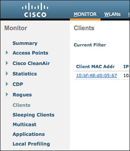
Figure 12-29 Monitor menu.
As shown in Figure 12-30, the Clients screen displays all current clients associated to the WLC, along with very valuable information, such as:
![]() IP Address—The IP address of the endpoint, when known.
IP Address—The IP address of the endpoint, when known.
![]() AP Name—The name of the access point to which the endpoint is associated.
AP Name—The name of the access point to which the endpoint is associated.
![]() WLAN Profile—The name of the WLAN profile created in the WLC.
WLAN Profile—The name of the WLAN profile created in the WLC.
![]() WLAN SSID—The name of the SSID for the WLAN profile, of which the endpoint has associated.
WLAN SSID—The name of the SSID for the WLAN profile, of which the endpoint has associated.
![]() User Name—With 802.1X, the username is displayed. When the endpoint is authenticated via wireless MAB, the MAC address will be displayed.
User Name—With 802.1X, the username is displayed. When the endpoint is authenticated via wireless MAB, the MAC address will be displayed.
![]() Auth—If the endpoint/supplicant has authenticated successfully, it will be listed here.
Auth—If the endpoint/supplicant has authenticated successfully, it will be listed here.
![]() Device Type—When the endpoint profile of the device is known, it will be displayed in this field.
Device Type—When the endpoint profile of the device is known, it will be displayed in this field.
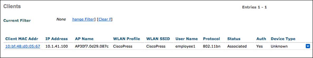
Figure 12-30 Monitor > Clients.
Figure 12-30 shows the clients monitor screen.
For much more detail, click the endpoint’s MAC address. This brings up the details related to the individual endpoint’s wireless session. As shown in Figure 12-31, a key value to verify for authentication is that the Policy Manager is in the RUN state. This means that all systems are go and the endpoint’s traffic will flow through the wireless controller normally.
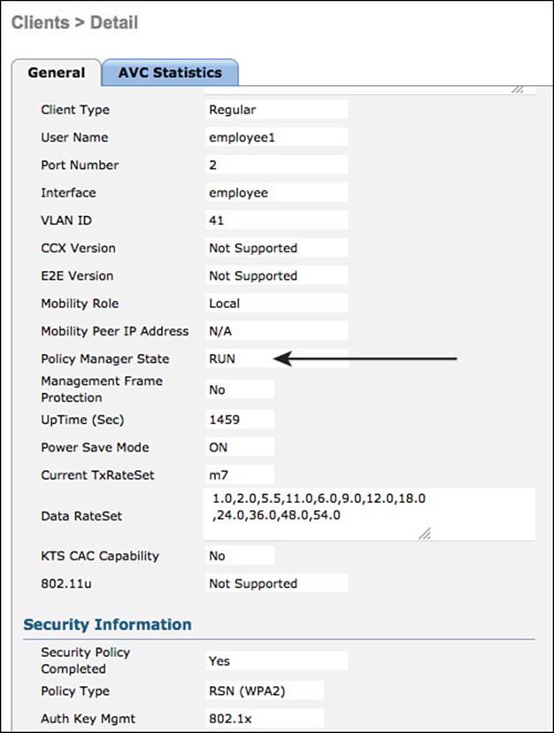
Figure 12-31 Monitor > Clients.
There are multiple states that an endpoint can be in. Those states are examined more in Chapter 13, “Web Authentication,” and Chapter 17, “Bring Your Own Device.”
Debug Client
The WLC provides a few useful debug commands: debug dot1x and debug client <mac-address>. debug dot1x can be a bit overwhelming on a live network, but the debug client command will show only events related to that specific endpoint. Example 12-4 shows an example of the debug client command.
Example 12-4 debug client <mac-address>
(Cisco Controller) >debug client 10:bf:48:d0:05:67
*Dot1x_NW_MsgTask_7: Jul 12 18:40:28.059: 10:bf:48:d0:05:67 Received EAPOL EAPPKT
from mobile 10:bf:48:d0:05:67
*Dot1x_NW_MsgTask_7: Jul 12 18:40:28.059: 10:bf:48:d0:05:67 Received Identity
Response (count=1) from mobile 10:bf:48:d0:05:67
*Dot1x_NW_MsgTask_7: Jul 12 18:40:28.059: 10:bf:48:d0:05:67 Resetting reauth count
1 to 0 for mobile 10:bf:48:d0:05:67
*Dot1x_NW_MsgTask_7: Jul 12 18:40:28.059: 10:bf:48:d0:05:67 EAP State update from
Connecting to Authenticating for mobile 10:bf:48:d0:05:67
*Dot1x_NW_MsgTask_7: Jul 12 18:40:28.059: 10:bf:48:d0:05:67 dot1x - moving mobile
10:bf:48:d0:05:67 into Authenticating state
*Dot1x_NW_MsgTask_7: Jul 12 18:40:28.059: 10:bf:48:d0:05:67 Entering Backend Auth
Response state for mobile 10:bf:48:d0:05:67
*Dot1x_NW_MsgTask_7: Jul 12 18:40:28.067: 10:bf:48:d0:05:67 Processing Access-
Challenge for mobile 10:bf:48:d0:05:67
Cisco ISE Verification
Validating the authentication from the NAD has a lot of value, but many times it is preferable to see the authentications from a central console. Cisco ISE is that central console. ISE has the Live Authentications Log (commonly known as Live Log) and Live Sessions Log (commonly known as Live Sessions).
Live Authentications Log
To view the Live Authentications Log (Live Log), navigate to Operations > Authentications, as shown in Figure 12-32.
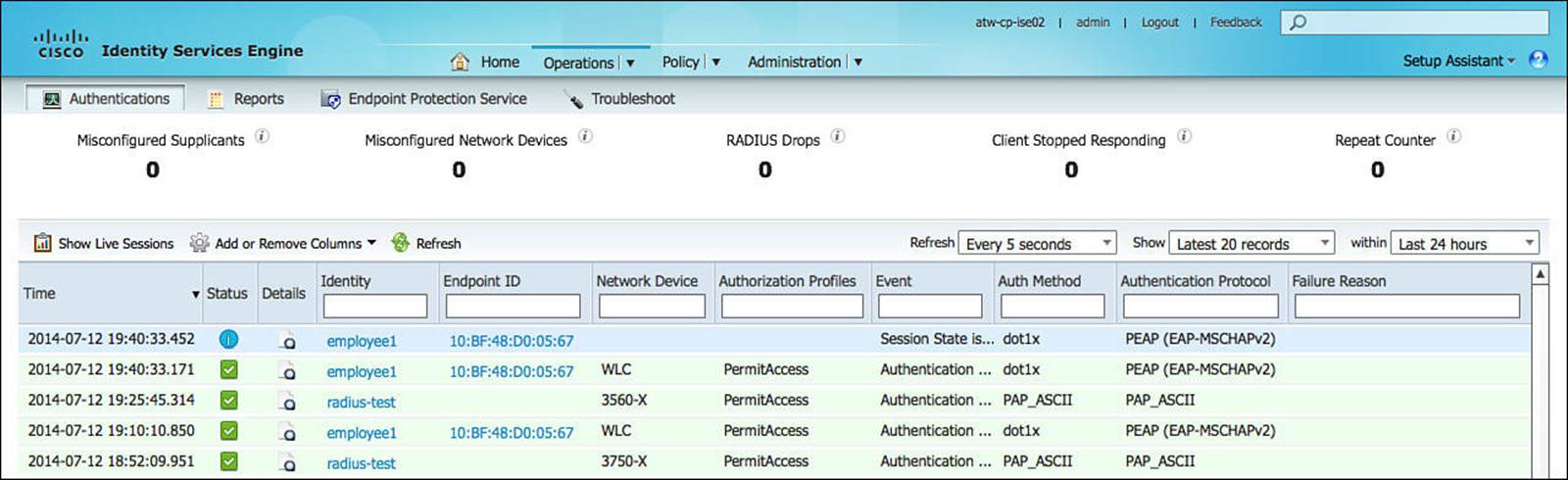
Figure 12-32 Live Authentications Log.
As shown in Figure 12-32, Live Log displays a near real-time display of authentication activity for the ISE Cube (also called ISE deployment). In Figure 12-32, you will see successful authentications from the radius-test account, which represents the automated testing performed by the wired switches. Additionally, the figure shows successful wireless authentications from employee1.
The Live Authentication Log is covered in greater detail throughout this book.
Live Sessions Log
To view the Live Sessions Log (Live Sessions), click the Show Live Sessions button in Live Log, as shown in Figure 12-33.
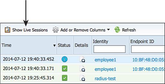
Figure 12-33 Live Authentications Log.
As shown in Figure 12-34, Live Log displays a correlated view of all activity related to an authentication session. If an endpoint changes state, that change will be listed in this view.
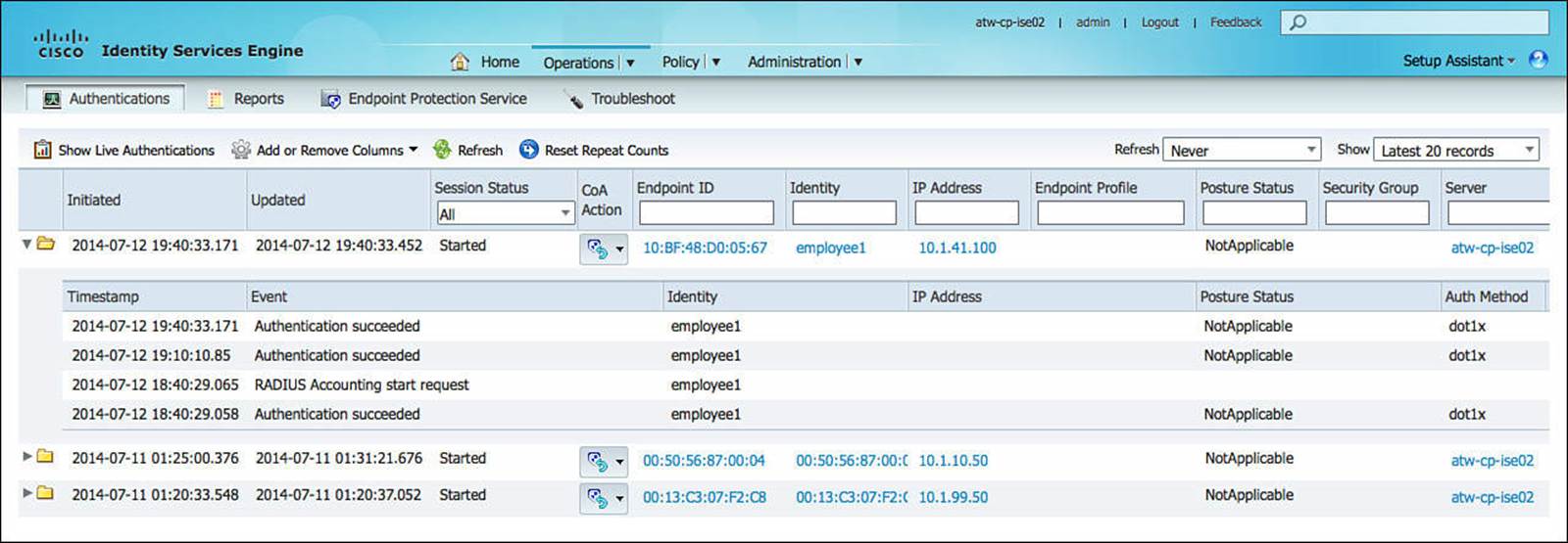
Figure 12-34 Live Sessions Log.
The Live Sessions Log is covered in greater detail throughout this book.
Looking Forward
While this chapter has covered the required configuration(s) for switches and wireless controllers to perform 802.1X and MAB authentications successfully with ISE, these NADs will be responsible for so much more than just basic authentication and authorization. Local ACLs will need to be deployed to define what traffic should be redirected for all use cases, possibly configuring Security-group eXchange Protocol (SXP) and other specific items. Those specific NAD configurations are covered in Chapter 13; Chapter 14, “Deploying Guest Services”; Chapter 17; and Chapter 18, “TrustSec and MACSec.”
Exam Preparation Tasks
Review All Key Topics
Review the most important topics in the chapter, noted with the key topics icon in the outer margin of the page. Table 12-2 lists a reference of these key topics and the page numbers on which each is found.
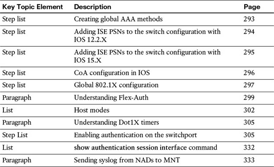
Table 12-2 Key Topics for Chapter 12
Define Key Terms
Define the following key terms from this chapter, and check your answers in the glossary:
flexible authentication (Flex-Auth)
network access device (NAD)
change of authorization (CoA)
vendor-specific attributes (VSAs)
MAC authentication bypass (MAB)
single-host
multiple domain authentication (MDA)
multiple authentication (Multi-Auth)
multi-host
Cisco Discovery Protocol (CDP) Second port disconnect
EAPoL-Proxy-Logoff
port security
All materials on the site are licensed Creative Commons Attribution-Sharealike 3.0 Unported CC BY-SA 3.0 & GNU Free Documentation License (GFDL)
If you are the copyright holder of any material contained on our site and intend to remove it, please contact our site administrator for approval.
© 2016-2026 All site design rights belong to S.Y.A.