Implementing Cisco IOS Network Security (IINS) Foundation Learning Guide, Second Edition (2013)
Part III: Threat Control and Containment
Chapter 8. Access Control Lists for Threat Mitigation
Cisco provides basic traffic filtering capabilities with access control lists (ACL). You can configure ACLs for all routed network protocols to filter packets as the packets pass through a router or security appliance. There are many reasons to configure ACLs; for example, you can use ACLs to restrict the contents of routing updates or to provide traffic flow control. One of the most important reasons to configure ACLs is to provide security for your network; this is the reason on which this chapter focuses.
This chapter outlines the types of ACLs that are available and provides guidelines that help create ACLs to provide network security in IPv4 and IPv6 environments. More precisely, this chapter
• Lists the benefits of ACLs
• Describes the building blocks and operational framework of ACLs
• Describes summarizable address blocks in the context of CIDR and VLSM environments, demonstrating how ACL wildcard masks allow for threat mitigation in those environments
• Lists design considerations when deploying ACLs
• Demonstrates the use of Cisco Configuration Professional and the CLI to deploy and verify a threat containment strategy using ACLs
• Demonstrates the use of Cisco Configuration Professional and the CLI to correlate ACL log and alarm information in order to monitor their impact and effectiveness
• Demonstrates how to configure object groups to streamline the implementation of ACLs for threat control
• Demonstrates how to configure ACLs in IPv6 environments, highlighting the operational differences with IPv4 ACLs
ACL Fundamentals
ACLs provide packet filtering for routers and firewalls to protect internal networks from the outside world. ACLs filter network traffic in both directions by controlling whether to forward or block packets at the router interfaces, based on the criteria that you specify within the ACLs. ACL criteria could be the source address of the traffic, the destination address of the traffic, the upper-layer protocol, or other information. Be aware, however, that sophisticated users (hackers) can sometimes successfully evade or fool basic ACLs not only because authentication is not required, but mainly because of the inability of an ACL to track the state of a connection.
ACLs provide a basic level of security for accessing your network. If you do not configure ACLs on your router, all packets passing through the router could get to all parts of your network. You can use ACLs on a router that is positioned between two parts of your network to control traffic entering or exiting a specific part of your internal network. An ACL on the router allows one host to access a part of your network and prevents another host from accessing the same area. The ACL shown in Figure 8-1 allows Host A to access the Human Resources network but prevents Host B from accessing the Human Resources network.
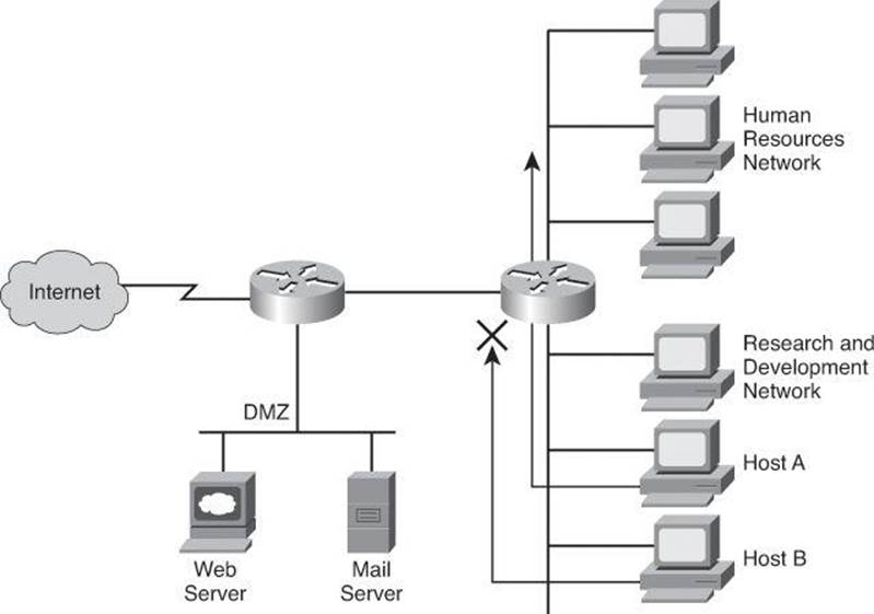
Figure 8-1. Filtering Host B Traffic Ingress Using an ACL
To provide the security benefits of ACLs, you should, at a minimum, configure ACLs at the perimeter of your networks. This configuration provides a basic buffer from the outside network, or from a less-controlled area of your own network into a more sensitive area of your network. On these network edge routers, you should configure ACLs for each network protocol that is configured on the router interfaces.
You can use ACLs to mitigate many threats:
• IP address spoofing (inbound)
• IP address spoofing (outbound)
• DoS TCP SYN attacks (blocking external attacks)
• DoS TCP SYN attacks (using TCP intercept)
• DoS Smurf attacks
• Filtering ICMP messages (inbound)
• Filtering ICMP messages (outbound)
• Filtering traceroute
Note
The System Administration, Networking, and Security (SANS) Institute offers a guide to protecting your Cisco IOS router, Cisco Router Hardening Step-by-Step, available at http://www.sans.org/reading_room/whitepapers/firewalls/cisco-router-hardening-step-by-step_794. The National Security Agency (NSA) also offers a guide on this topic, Router Security Configuration Guide, at http://www.nsa.gov/ia/mitigation_guidance/security_configuration_guides/cisco_router_guides.shtml.
Tip
Two terms you’ll encounter in this chapter that are commonly confused are egress and ingress. Egress refers to traffic leaving the network or device. Ingress refers to traffic entering the network or device.
Cisco routers use ACLs as packet filters to decide which packets can access a router service or cross an interface. Packets that are allowed across an interface are permitted packets. Packets that are not allowed across an interface are denied packets.
An ACL enforces one or more corporate security policies. For example, a corporate security policy might allow to access the Internet only packets using source addresses from within the trusted network. Once this policy is written, you can develop an ACL that includes certain statements that, when applied to a router interface, can implement this policy.
Cisco router security depends strongly on well-written ACLs to restrict access to router network services and to filter packets as they traverse the router.
ACLs express the sets of rules that give added control over packets that enter inbound interfaces, packets that relay through the router, and packets that exit outbound interfaces of the router. ACLs do not act on packets that originate from the router itself. Instead, ACLs are statements that specify conditions of how the router handles the traffic flow through specified interfaces.
ACLs operate in two ways:
• Inbound: Incoming packets are processed before they are routed to an outbound interface. An inbound ACL is efficient because it saves the overhead of routing lookups if the packet will be discarded after it is denied by the filtering tests. If the packet is permitted by the tests, it is then processed for routing.
• Outbound: Packets arriving on the inside interface are routed to the outbound interface, and then they are processed through the outbound ACL.
Figure 8-2 shows an example of an outbound ACL. When a packet enters an interface, the router checks the routing table to see whether the packet is routable. If the packet is not routable, it is dropped.
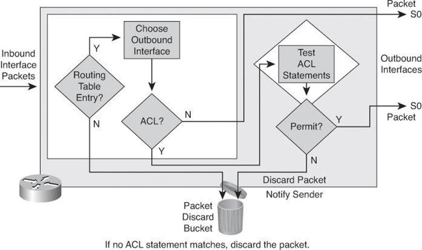
Figure 8-2. Outbound ACL Operation
Next, the router checks to see whether the destination interface is grouped to an ACL. If the destination interface is not grouped to an ACL, the packet can be sent to the output buffer. Examples of outbound ACL operation are as follows:
• If the outbound interface selected by the routing process is not grouped to an outbound ACL, the packet is sent directly to that outbound interface, which is S0 in the example in Figure 8-2.
• If the outbound interface selected by the routing process is grouped to an outbound ACL, the packet is not sent out directly to that outbound interface, which is S0 in the example in Figure 8-2. The packet must first be tested by the combination of ACL statements associated with that interface. Based on the ACL tests, the packet is permitted or denied.
For outbound lists, to permit means to send the packet to the output buffer, and to deny means to discard the packet.
With an inbound ACL, when a packet enters an interface, the router checks to see whether the source interface is grouped to an ACL. If the source interface is not grouped to an ACL, the router checks the routing table to see whether the packet is routable. If the packet is not routable, the router drops the packet. Examples of inbound ACL operation are as follows:
• If the inbound interface is E0, for example, which has not been grouped to an inbound ACL, the packet is processed normally and the router checks to determine whether the packet is routable.
• If the inbound interface is E1, for example, which has been grouped to an inbound ACL, the packet is not processed and the routing table is not consulted until the packet is tested by the ACL that is associated with that interface. Based on the ACL tests, the packet is permitted or denied.
For inbound lists, permit means to continue to process the packet after receiving it on an inbound interface, and deny means to discard the packet.
ACL statements operate in a sequential, logical order, as shown in Figure 8-3. They evaluate packets from the top down, one statement at a time. If a packet header and an ACL statement match, the rest of the statements in the list are skipped, and the packet is permitted or denied as determined by the matched statement. If a packet header does not match an ACL statement, the packet is tested against the next statement in the list. This matching process continues until the end of the list is reached.
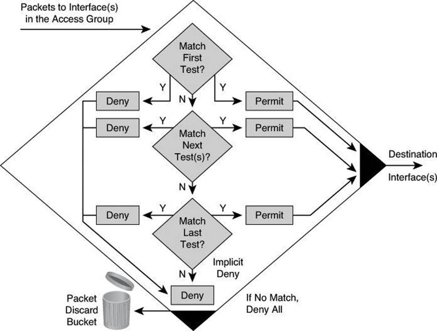
Figure 8-3. Top-Down Process of Tests: Deny or Permit
A final implied statement covers all packets for which conditions did not test true. This final test condition matches all other packets and results in a “deny” instruction. Instead of proceeding into or out of an interface, the router drops all of these remaining packets. This final statement is often referred to as the “implicit deny any statement.” Because of this statement, an ACL should have at least one permit statement in it; otherwise, the ACL blocks all traffic.
Types of IP ACLs
Cisco routers support two types of IP ACLs:
• Standard ACLs: Standard IP ACLs check the source addresses of packets that can be routed. The result either permits or denies the output for an entire protocol suite, based on the source network, subnet, or host IP address.
• Extended ACLs: Extended IP ACLs check both the source and destination packet addresses. They can also check for specific protocols, port numbers, and other parameters, which allows administrators more flexibility and control.
The two general methods you can use to create ACLs are as follows:
• Numbered ACLs: Use a number for identification.
• Named ACLs: Use an alphanumeric string for identification.
Using numbered ACLs is an effective method on smaller networks with more homogeneously defined traffic. Because each ACL type is limited to an assigned range of numbers, it is easy to determine the type of ACL that you are using.
Specifying an ACL number from 1 to 99 or 1300 to 1999 instructs the router to accept numbered standard IP Version 4 (IPv4) ACL statements. Specifying an ACL number from 100 to 199 or 2000 to 2699 instructs the router to accept numbered extended IPv4 ACL statements.
The named ACL feature allows you to identify IP standard and extended ACLs with an alphanumeric string (name) rather than the numeric representations. Named IP ACLs provide you more flexibility in working with the ACL entries.
Tip
The number of the ACL determines which protocol it is filtering: 1 to 99 and 1300 to 1999 define standard IP ACLs. 100 to 199 and 2000 to 2699 define extended IP ACLs.
Named ACLs have been available since Cisco IOS Software Releases 11.2. Names contain alphanumeric characters. Names cannot contain spaces or punctuation and must begin with an alphabetic character. Named ACLs enable you to add or delete entries within the ACL.
There are two benefits to IP ACL entry sequence numbering:
• You can edit the order of ACL statements.
• You can remove individual statements from an ACL.
Where additions are placed in an ACL depends on whether you use sequence numbers. If you don’t specify a sequence number, new ACL statements are placed at the end of the ACL.
Removing ACL statements is also streamlined with sequence numbers. If you want to remove a single entry, you can do it by referencing the entry number (or sequence number) with the no access-list command. It is best practice to space out the entry sequence number to leave room to add intermediate entries in the future. As an example, the first entry could be sequenced 10, the second entry 20, and so forth. Should an entry need to be inserted between 10 and 20, you could sequence it 15. Also note that Cisco lets you resequence an ACL and select the increment. A good reference on this can be found at http://www.cisco.com/en/US/docs/ios/12_2s/feature/guide/fsaclseq.html.
Note
ACLs that are applied to an interface do not filter traffic that is generated by the router.
ACL Wildcard Masking and VLSM Review
Address filtering occurs when you use ACL address wildcard masking to identify how to check or ignore corresponding IP address bits. However, prior to jumping into ACL wildcard masking, let’s review subnetting, including variable-length subnet masking (VLSM), which was covered amply in the CCNA material that you studied for the ICND2 exam. Please consult CCNA Preparation Library (Cisco Press) for thorough presentations on IP addresses, subnetting, and VLSM.
Subnetting Overview
To understand ACL filtering in classless interdomain routing (CIDR) and VLSM environments, we must start with a review of subnetting.
Remember that an IP address has 32 bits and comprises two parts—a network ID and a host ID. The length of the network ID and host ID depends on the class of the IP address. The number of hosts available also depends on the class of the IP address.
The default number of bits in the network ID is referred to as the classful prefix length. Therefore, a Class A address has a classful prefix length of /8, a Class B address has a classful prefix length of /16, and a Class C address has a classful prefix length of /24.
The number of hosts per subnet available depends upon the number of host ID bits not borrowed.
Subnetting Example: Class C
The subnet address is created by taking address bits from the host-number portion of Class A, Class B, and Class C addresses. Usually a network administrator assigns the subnet address locally. Like IP addresses, each subnet address must be unique.
Each time one bit is borrowed from a host field, there is one less bit remaining in the host field that can be used for host numbers, and the number of host addresses that can be assigned per subnet decreases by a power of 2. Figure 8-4 shows an example for Class C addresses.
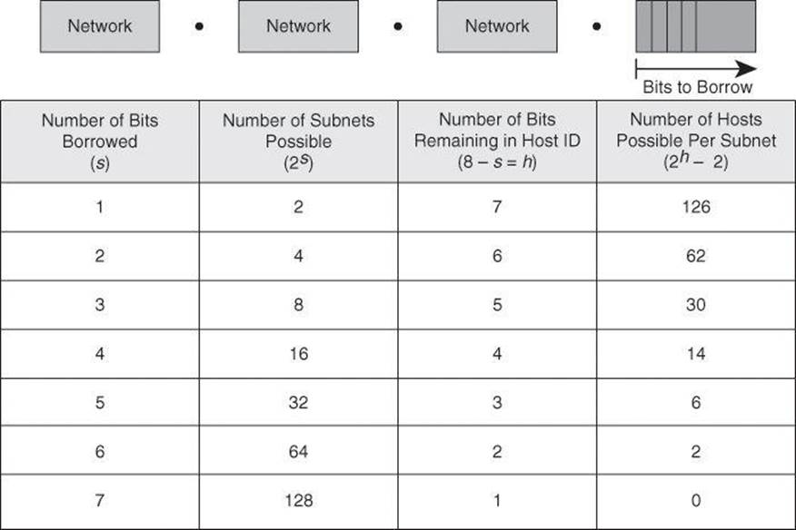
Figure 8-4. Subnetting a Class C Address
When you borrow bits from the host field, it is important to note the number of additional subnets that are being created each time one more bit is borrowed. Borrowing two bits creates four possible subnets (2 × 2 = 4). Each time another bit is borrowed from the host field, the number of possible subnets increases by a power of 2 and the number of individual host addresses decreases by a power of 2.
The following are examples of how many subnets are available, based on the number of host bits that you borrow:
• Using 3 bits for the subnet field results in 8 possible subnets (23 = 8).
• Using 4 bits for the subnet field results in 16 possible subnets (24 = 16).
• Using 5 bits for the subnet field results in 32 possible subnets (25 = 32).
• Using 6 bits for the subnet field results in 64 possible subnets (26 = 64).
In general, you can use the following formula to calculate the number of usable subnets, given the number of subnet bits used:
Number of subnets = 2s (in which s is the number of subnet bits)
In general, you can use the following formula to calculate the number of hosts per subnet, given the number of host bits used:
Number of hosts per subnet = 2h – 2, in which h is the number of host bits not borrowed.
We subtract two host addresses from the total because one address is reserved as the network address (the address where all host bits are set to 0) and one address is reserved as the broadcast address (the address where all host bits are set to 1).
Subnetting Example
Subnet a network with a private network address of 172.16.0.0/16 so that it provides ten subnets and maximizes the number of host addresses for each subnet. Answer the following questions:
• How many bits will need to be borrowed for subnets? 2s = 27 = 128 subnets (s = 7 bits).
• What is the new subnet mask? Borrowing 7 host bits = 255.255.254.0 or /23.
• What are the first four subnets?
• 172.16.0.0
• 172.16.2.0
• 172.16.4.0
• 172.16.6.0
• What is the range of host addresses for the four subnets?
• 172.16.0.1–172.16.1.254
• 172.16.2.1–172.16.3.254
• 172.16.4.1–172.16.5.254
• 172.16.6.1–172.16.7.254
Variable-Length Subnet Masking
VLSM affords the options of including more than one subnet mask within a network and of subnetting an already subnetted network address. VLSM offers the following benefits:
• More efficient use of IP addresses: Without the use of VLSMs, companies must implement a single subnet mask within an entire Class A, B, or C network number.
For example, consider the 172.16.0.0/16 network address divided into subnetworks using /24 masking. One of the subnetworks in this range, 172.16.14.0/24, is further divided into smaller subnetworks using /27 masking, as shown in Figure 8-5. These smaller subnetworks range from 172.16.14.0/27 to 172.16.14.224/27. In Figure 8-5, one of these smaller subnets, 172.16.14.128/27, is further divided using the /30 prefix, which creates subnets with only two hosts, to be used on the WAN links. The /30 subnets range from 172.16.14.128/30 to 172.16.14.156/30. In Figure 8-5, the WAN links used the 172.16.14.132/30, 172.16.14.136/30, and 172.16.14.140/30 subnets from the range.
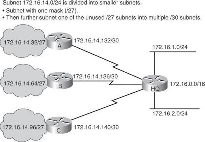
Figure 8-5. Example of Variable-Length Subnet Mask for 172.16.0.0/16
• Greater capability to use route summarization: VLSM allows more hierarchical levels within an addressing plan and thus allows better route summarization within routing tables.
For example, in Figure 8-5, subnet 172.16.14.0/24 summarizes all of the addresses that are further subnets of 172.16.14.0, including those from subnet 172.16.14.0/27 and from subnet 172.16.14.128/30.
• Isolation of topology changes from other routers: Another advantage to using route summarization in a large, complex network is that it can isolate topology changes from other routers. For example, when a specific link in the 172.16.27.0/24 domain is rapidly fluctuating between being active and inactive (called flapping), the summary route does not change. Therefore, no router that is external to the domain needs to keep modifying its routing table because of this flapping activity.
A Working VLSM Example
The example in Figure 8-6 shows an address space defined by the subnet address 172.16.32.0/20. This address space is used for this portion of the enterprise network, and is generated from subnetting the 172.16.0.0/16 Class B network into multiple /20 subnets.
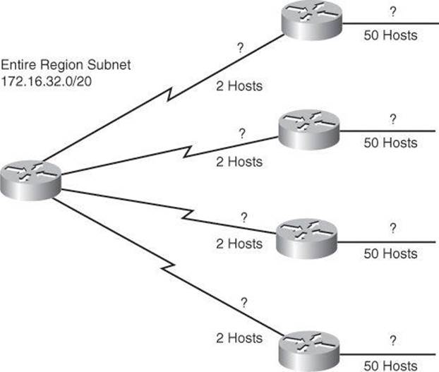
Figure 8-6. Working VL SM Example
How would you define the subnets and masks to assign IP addresses to the WAN links, which require 2 host IP addresses, and the LAN segments, each one showing a requirement of 50 hosts?
By using VLSM, you can further subnet an already subnetted address. Consider again the example address space shown in Figure 8-6. Your region of the enterprise network has a subnet address of 172.16.32.0/20 and you need to assign addresses to multiple LANs, each with 50 hosts, within your region. With VLSM, you can further subnet address 172.16.32.0/20 to give you more network addresses and fewer hosts per network. For example, as shown in Figure 8-7, if you subnet 172.16.32.0/20 to 172.16.32.0/26, you gain 64 (26) subnets, each of which could support 62 (26 – 2) hosts.
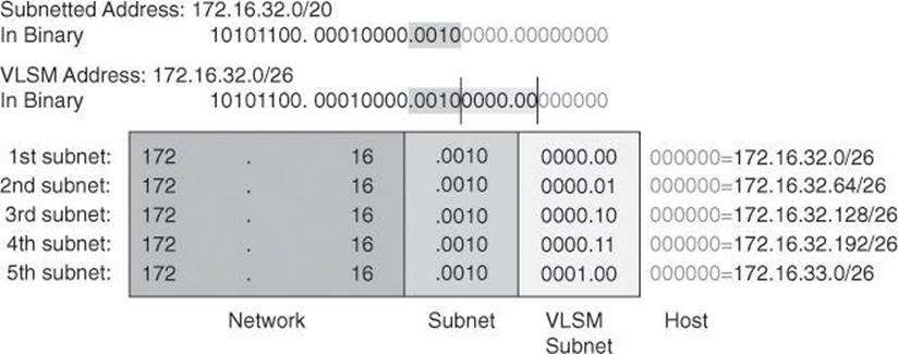
Figure 8-7. VLSM for 172.16.32.0/20
To calculate the subnet addresses that are used on the WAN links, further subnet one of the unused /26 subnets using a similar process.
The resulting address space and subnetting strategy is shown in Figure 8-8. The subnet addresses that are used on the Ethernet LANs are those generated from subdividing the 172.16.32.0/20 subnet into multiple /26 subnets.
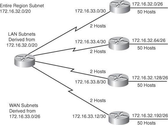
Figure 8-8. LANs and Point-to-Point Subnets for 172.16.32.0/20
The subnet addresses that are used on the WAN links are those generated from subdividing one of the /26 subnets, the 172.16.33.0/26 subnet, into multiple /30 subnets. This provides 16 (24) subnets and 2 (22 – 2) hosts for each of the WAN links.
ACL Wildcard Bits
One of the benefits of proper summarization is the efficient use of wildcard masks in ACLs for packet filtering purposes.
In ACLs, address filtering occurs when you use ACL address wildcard masking to identify how to check or ignore corresponding IP address bits. Wildcard masking for IP address bits uses the numbers 1 and 0 to identify how to treat the corresponding IP address bits, as follows:
• Wildcard mask bit 0: Match the corresponding bit value in the address.
• Wildcard mask bit 1: Do not check (ignore) the corresponding bit value in the address.
Note
A wildcard mask is sometimes referred to as an inverse mask. Be aware, however, that you should use regular subnet masks if you are configuring ACLs on a Cisco ASA.
Figure 8-9 illustrates how wildcard bits are used to check the corresponding address bits.
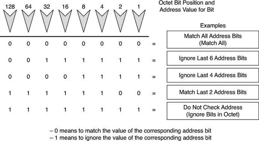
Figure 8-9. Wildcard Bits: How to Check the Corresponding Address Bits
By carefully setting wildcard masks, you can permit or deny tests with one ACL statement. You can select a single IP address or any IP address.
Example: Wildcard Masking Process for IP Subnets
In Figure 8-10, an administrator wants to test a range of IP subnets that is to be permitted or denied. Assume that the IP address is a Class B address (the first two octets are the network number), with 8 bits of subnetting (the third octet is for subnets). The administrator wants to use the IP wildcard masking bits to match subnets 172.30.16.0/24 to 172.30.31.0/24.
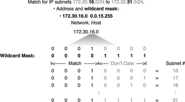
Figure 8-10. Wildcard Bits to Match IP Subnets 172.30.16.0 to 172.30.31.0
To use one ACL statement to match this range of subnets, use the IP address 172.30.16.0 in the ACL, which is the first subnet to be matched, followed by the required wildcard mask.
First, the wildcard mask matches the first two octets (172.30) of the IP address using corresponding 0 bits in the first two octets of the wildcard mask.
Because there is no interest in an individual host, the wildcard mask ignores the final octet by using the corresponding 1 bit in the wildcard mask. For example, the final octet of the wildcard mask is 255 in decimal.
In the third octet, where the subnet address occurs, the wildcard mask of decimal 15, or binary 00001111, shown in bold, matches the high-order 4 bits of the IP address. In this case, the wildcard mask matches subnets starting with the 172.30.16.0/24 subnet. For the final (low-end) 4 bits in this octet, shown in gray, the wildcard mask indicates that the bits can be ignored. In these positions, the address value can be binary 0 or binary 1. Thus, the wildcard mask matches subnets 16, 17, 18, and so on up to subnet 31. The wildcard mask does not match any other subnets.
In Figure 8-10, the address 172.30.16.0 with the wildcard mask 0.0.15.255 matches subnets 172.30.16.0/24 to 172.30.31.0/24.
In some cases, you must use more than one ACL statement to match a range of subnets. For example, to match 10.1.4.0/24 to 10.1.8.0/24, use 10.1.4.0 0.0.3.255 and 10.1.8.0 0.0.0.255.
From your previous knowledge acquired in ICND2 (CCNA), you will remember the following command syntax, which we will review in more detail in a moment. So, suppose that you want to block all IP traffic from the range of subnets shown in Figure 8-10; the ACL could be this:
Router(config)# access-list 1 deny 172.30.16.0 0.0.15.255
The 0 and 1 bits in an ACL wildcard mask cause the ACL to either match or ignore the corresponding bit in the IP address. Working with decimal representations of binary wildcard mask bits can be tedious. For the most common uses of wildcard masking, you can use abbreviations. These abbreviations reduce how many numbers you are required to enter while configuring address test conditions.
Example: Wildcard Masking Process with a Single IP Address
In Figure 8-11, instead of entering 172.30.16.29 0.0.0.0, you can use the string host 172.30.16.29. Using the abbreviation host communicates the same test condition to the Cisco IOS ACL Software. The command syntax using the abbreviation host is as follows:
Router(config)# access-list 2 permit host 172.30.16.29
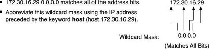
Figure 8-11. ACL and the host Keyword
And this is the same as entering the following:
Router(config)# access-list 2 permit 172.30.16.29 0.0.0.0
Should you enter the full host mask of 0.0.0.0, the router will convert the command for the host abbreviation automatically.
Example: Wildcard Masking Process with a Match Any IP Address
In Figure 8-12, instead of entering 0.0.0.0 255.255.255.255, you can use the word any by itself as the keyword. Using the abbreviation any communicates the same test condition to the Cisco IOS ACL Software. Both syntaxes, which accomplish the same results, are as follow, first in the long form, then using the keyword any:
Router(config)# access-list 2 permit 0.0.0.0 255.255.255.255
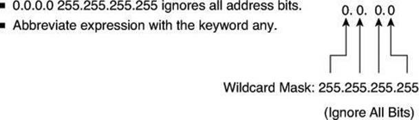
Figure 8-12. ACL and the any Keyword
And this is the same as entering the following:
Router(config)# access-list 2 permit any
Tip
As a matter of fact, you can enter any valid host IP address followed by the wildcard mask of 255.255.255.255 and the router will convert your entry to the keyword any, as demonstrated by the following test:
YYZ(config)# access-list 3 deny 192.168.16.214 255.255.255.255
YYZ(config)# do show access-list 3
Standard IP access list 3
10 deny any
YYZ(config)#
Using ACLs to Control Traffic
To configure numbered standard IPv4 ACLs on a Cisco router, you must create a standard IPv4 ACL and activate an ACL on an interface. The access-list command creates an entry in a standard IPv4 traffic filter list.
The following is the syntax for the access-list command:
Router(config)# access-list access-list-number {permit | deny | remark} source-
address [mask] [log]
To create an ACL, use 1 to 99 for the access-list-number parameter. The first entry is assigned a sequence number of 10, and successive entries are incremented by 10. The default wildcard mask is 0.0.0.0 (only standard ACL). The remark argument lets you add a description to the ACL.
Caution
The no access-list access-list-number command removes the entire ACL.
The log option of the access-list command causes an informational logging message to be created about the packet that matches the ACE.
Tip
You control the level of messages that are logged to the console using the logging console command. You can also have the messages kept in buffer with the logging buffered command. The number of system error and debugging messages in the system logging buffer is determined by the configured size of the syslog buffer. This size of the syslog buffer is also set using the logging buffered command.
The logging message includes the ACL number, whether the packet was permitted or denied, the source address, and the number of packets. The message is generated for the first packet that matches, and then at five-minute intervals, including the number of packets permitted or denied in the previous five-minute interval. This five-minute interval prevents firewall resources from being consumed for repetitive packets from the same flow.
The ip access-group command links an existing ACL to an interface. Only one ACL per protocol, per direction, and per interface is allowed. The syntax for this command is as follows:
Router(config-if)# ip access-group access-list-number {in | out}
Note
To remove an IP ACL from an interface, first enter the no ip access-group command on the interface; then enter the global no access-list command to remove the entire ACL.
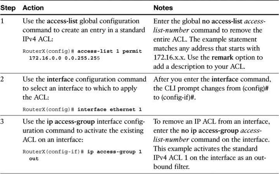
Table 8-1 provides an example of the steps required to configure and apply a numbered standard ACL on a router.
Table 8-1. Numbered Standard ACL Configuration Procedure
Example: Numbered Standard IPv4 ACL—Deny a Specific Subnet
Table 8-2 describes the command syntax that is presented in Example 8-1 for the network topology shown in Figure 8-13.
Table 8-2. Numbered Standard IPv4 ACL Example
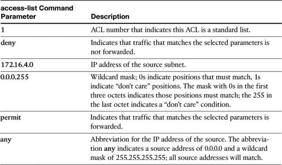
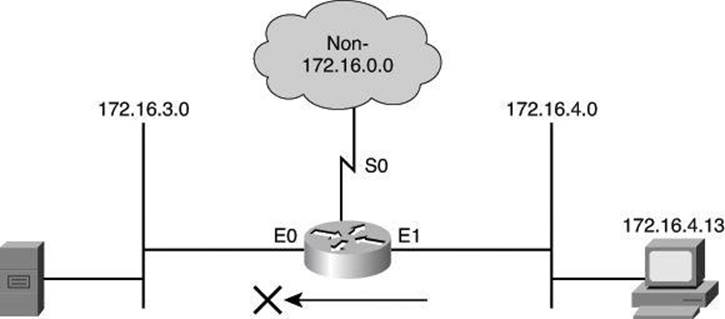
Figure 8-13. Numbered Standard IPv4 ACL
Example 8-1. Numbered Standard IPv4 ACL
r1(config)# access-list 1 deny 172.16.4.0 0.0.0.255
r1(config)# access-list 1 permit any
( implicit deny all = access-list 1 deny 0.0.0.0 255.255.255.255 )
r1(config)# interface ethernet 0
r1(config-if)# ip access-group 1 out
The ACL shown in Example 8-1 is designed to block traffic from a specific subnet, 172.16.4.0, and to allow all other traffic to be forwarded out E0. However, traffic from subnet 172.16.4.0 is not filtered when leaving by S0.
vty Access
To control traffic into and out of the router (not through the router), you protect the router virtual ports. A virtual port (or virtual terminal line) is commonly referred to as vty. By default, there are five such virtual terminal lines, numbered vty 0 through vty 4. You can configure Cisco IOS Software images to support more than five vty ports.
Restricting vty access is primarily a technique for increasing network security and defining which addresses are allowed Telnet access to the router EXEC process.
The command used to filter Telnet traffic is as follows:
Router(config-line)# access-class access-list-number {in | out}
Filtering Telnet traffic is typically considered an extended IP ACL function because it filters a higher-level protocol. However, because you are using the access-class command to filter incoming or outgoing Telnet sessions by source address and apply filtering to vty lines, you can use standard IP ACL statements to control vty access.
The following example applies a standard ACL to control vty access. It permits any device on network 192.168.1.0 0.0.0.255 to establish a virtual terminal session with the router. Of course, the user must know the appropriate passwords to enter user mode and privileged mode. This example assumes that the protocol used to exchange with the router is Telnet; however, other protocol can be filtered by the access-class command, such as Secure Shell (SSH).
R1(config)# access-list 12 permit 192.168.1.0 0.0.0.255
!
R1(config)# line vty 0 4
R1(config-line)# access-class 12 in
Notice that identical restrictions have been set on every vty line (0 to 4) because you cannot control on which vty line a user will connect. The implicit deny any statement still applies to the ACL when it is used as an access class entry.
Numbered Extended IPv4 ACL
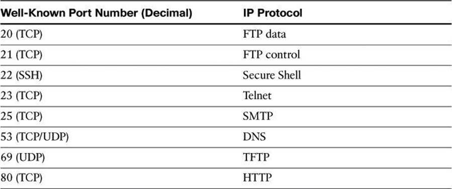
To provide more precise traffic-filtering control, use extended IPv4 ACLs, which are named or numbered 100 to 199 and 2000 to 2699, because extended IPv4 ACLs check for the source and destination IPv4 addresses. In addition, with an extended ACL statement, you can specify the protocol and, optionally, TCP or UDP application to filter traffic more precisely. To specify an application, you can configure either the port number or name of a well-known application.
Table 8-3 shows some well-known port numbers of IP protocols that you can use with extended ACLs.
Table 8-3. Well-Known Port Numbers and IP Protocols
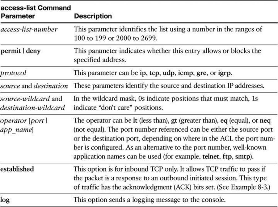
To configure numbered extended IPv4 ACLs on a Cisco router, create an extended IPv4 ACL and activate that ACL on an interface. Use the access-list command to create an entry to express a condition statement in a complex filter. Table 8-4 explains the syntax of the command for configuring a numbered extended ACL, shown here:
Router(config)# access-list access-list-number {permit | deny}
protocol source source-wildcard [operator port] destination
destination-wildcard [operator port] [established] [log]
Table 8-4. Command Parameters for a Numbered Extended ACL
Note
The syntax of the access-list command that is presented in Table 8-4 is representative of the TCP protocol form. Not all parameters and options are given. For the complete syntax of all forms of the command, refer to the appropriate Cisco IOS Software documentation available at Cisco.com.
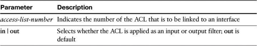
To link an existing extended ACL to an interface, use the following command:
Router(config-if)# ip access-group access-list-number (in | out)
Only one ACL per protocol, per direction, and per interface is allowed.
Table 8-5 describes the parameters of the ip access-group command.
Table 8-5. ip access-group Command Parameters
Example 8-2 shows the configuration for denying FTP access from subnet 172.16.4.0/24 to subnet 172.16.3.0/24, for the network depicted in Figure 8-14. All other traffic is allowed. By applying the ACL to the E0 interface in an outbound direction, traffic is dropped just before it would be transmitted out the E0 interface.
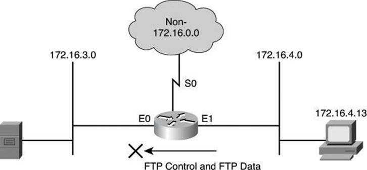
Figure 8-14. Numbered Extended IPv4 ACL Example
Example 8-2. Numbered Extended IPv4 ACL Example
r1(config)# access-list 101 deny tcp 172.16.4.0 0.0.0.255 172.16.3.0 0.0.0.255 eq 21
r1(config)# access-list 101 deny tcp 172.16.4.0 0.0.0.255 172.16.3.0 0.0.0.255 eq 20
r1(config)# access-list 101 permit ip any any
(implicit deny all)
(access-list 101 deny ip 0.0.0.0 255.255.255.255 0.0.0.0 255.255.255.255)
r1(config)# interface ethernet 0
r1(config-if)# ip access-group 101 out
Notice the use of wildcard masks to define how to check or ignore the corresponding IP address bits. In the example in Figure 8-14, the first access control entry (ACE) matches source addresses in the 172.16.4.0 subnet. The way to check only the first 3 bytes on this prefix is to follow the prefix with the wildcard mask 0.0.0.255. Zeroes (0) in the wildcard mask tell the ACL to check the corresponding bit of packet addresses with the prefix. Ones (1) in the wildcard mask tell the ACL not to check the corresponding bit of packet addresses with the prefix.
In Example 8-2, notice the wildcard mask. As explained earlier in the chapter, using wildcard masks is a valuable tool for creating effective and efficient ACLs, especially in CIDR environments.
In Example 8-3, the established parameter of the extended ACL allows responses to traffic that originate from the mail host, 200.1.1.2, to return inbound on the serial 0 interface. A match occurs if the TCP datagram has the ACK bit or reset (RST) bit set, which indicates that the packet belongs to an existing connection. Without the established parameter in the ACL statement, the mail host could receive SMTP traffic but not send it.
Caution
ACLs using the keyword established are not a substitute for a stateful firewall. The ACL only checks whether the ACK (acknowledgement) flag bit is turned on in the TCP header, without reference to other prior transmission. In other words, as long as the ACK bit is turned on and the other filtering criteria mentioned in the ACL entry are valid, the router will execute the action. It will not check to determine whether a proper TCP three-way handshake was done. It is therefore easy to fool the router using a packet-crafting tool.
Example 8-3. Using the established Keyword
Router(config)# access-list 102 permit tcp any host 200.1.1.2 established
Router(config)# access-list 102 permit tcp any host 200.1.1.2 eq smtp
Router(config)# interface serial 0
Router(config-if)# ip access-group 102 in
Displaying ACLs
When you finish the ACL configuration, use the show commands to verify the configuration. Use the show access-lists command to display the contents of all ACLs, as shown in Example 8-4. By entering the ACL name or number as an option for this command, you can display a specific ACL. To display the contents of only the IP ACLs, use the show ip access-list command.
Example 8-4. show access-lists Command Output
Router# show access-lists
Extended IP access list OUTBOUND
10 permit tcp 10.0.0.0 0.255.255.255 any eq www (67 matches)
20 permit tcp 10.0.0.0 0.255.255.255 any eq 443 (1190 matches)
30 permit udp 10.0.0.0 0.255.255.255 any eq domain
40 deny ip any any (41 matches)
Fast Switching and ACLs
Fast switching uses the route cache to store information about packet flows. The first packet in a flow is looked at thoroughly by the router, which performs Layer 3–to–Layer 2 mapping, selects the best route, the outbound interface, and its ACL, and decides whether the packet is allowed to leave. The decision taken on the first packet is stored in the route cache so that any subsequent packets from the same flow can be fast-switched or sent to Cisco Express Forwarding (CEF) without being looked at by the CPU, the interface ACL, and so forth.
If you enable CEF, a Layer 3 IP switching technology, and then create an ACL that uses the log keyword, the packets that match the ACL are not CEF switched. They are fast switched. ACL logging disables CEF.
The show ip interfaces command displays IP interface information and indicates whether any IP ACLs are set on the interface. In the show ip interfaces command output shown in Example 8-5, IP ACL OUTBOUND has been configured on the FastEthernet 0/0 interface as an inbound ACL. No outbound IP ACL has been configured on the FastEthernet interface.
Example 8-5. show ip interfaces Command Output
r1# show ip interfaces FastEthernet 0/0
FastEthernet 0/0 is up, line protocol is up
Internet address is 10.0.2.1/24
Broadcast address is 255.255.255.255
Address determined by non-volatile memory
MTU is 1500 bytes
Helper address is not set
Directed broadcast forwarding is disabled
Multicast reserved groups joined: 224.0.0.5 224.0.0.6
Outgoing access list is not set
Inbound access list is OUTBOUND
Proxy ARP is enabled
<text omitted>
Enhancing ACLs with Object Groups
ACLs provide basic security to the network by permitting or blocking certain types of traffic. ACLs use IP addresses, protocols, and ports to filter network traffic. In some networks, the number of ACLs can become quite large and difficult to manage. The Object Groups for ACLs feature simplifies this problem. By using the Object Groups for ACLs feature, the administrator can group users, devices, or protocols into object groups and create access control entries. Each ACE can then permit or deny a group of users access to a group of servers or services.
The benefits of using Object Groups for ACL include the following:
• Increased performance when network traffic is heavy.
• Reduced storage in NVRAM compared to conventional ACLs.
• Separate ownership of the components of an ACE. For example, you can create an ACE where each department within an organization can control its group membership. You can also create an ACE to permit or deny the departments to contact each other.
• Allows you to create an object group that contains other object groups. For example, you can create an ENG-ALL address group, which contains the ENG-EAST and ENG-WEST address groups.
In Example 8-6, an access rule results in eight access control entries in an ACL.
Example 8-6. Example of an ACL Without Object Group
access-list 100 deny tcp host 10.6.252.65 host 171.8.2.12 eq www
access-list 100 deny tcp host 10.6.252.65 host 171.8.2.12 eq ftp
access-list 100 deny tcp host 10.6.252.65 host 171.8.2.13 eq www
access-list 100 deny tcp host 10.6.252.65 host 171.8.2.13 eq ftp
access-list 100 deny tcp host 10.6.252.66 host 171.8.2.12 eq www
access-list 100 deny tcp host 10.6.252.66 host 171.8.2.12 eq ftp
access-list 100 deny tcp host 10.6.252.66 host 171.8.2.13 eq www
access-list 100 deny tcp host 10.6.252.66 host 171.8.2.13 eq ftp
With object groups, as shown in Example 8-7, you can modularize the sources in this example using object group SOURCES, which is a network object group. Another network object group called DESTINATIONS is used to modularize the destination IP addresses, and a service object group called APPLICATIONS is used to modularize the TCP ports in the example. The resulting ACL has one line and still matches all the sources, all the destinations, and all the services. Notice how object groups extend the conventional ACL syntax to support object group–based ACLs and also add new keywords along with the source and destination addresses and ports.
Example 8-7. Example of an ACL Using Object Groups
object-group network SOURCES
host 10.6.252.65 host 10.6.252.66
object-group network DESTINATIONS
host 171.8.2.12 host 171.8.2.13
object-group service APPLICATIONS
tcp www tcp ftp
access-list 100 deny object-group APPLICATIONS object-group SOURCES object-group
DESTINATIONS
When configuring object group–based ACLs, all features that use or reference conventional ACLs are compatible with object group–based ACLs. Feature interactions for conventional ACLs are the same with object group–based ACLs.
These rules also apply when creating object–group based ACLs:
• You can add to, delete from, or change objects in an object group membership list dynamically (meaning without deleting and redefining the object group).
• You can add to, delete from, or change objects in an object group membership list without redefining the ACL ACE that is using the object group (meaning changing the object group without deleting the ACE and then redefining the ACE after the change).
• You can add objects to groups, delete them from groups, and then ensure that the changes are properly functioning within the object group–based ACL without reapplying the ACL to the interface.
The following components can be modularized in network object groups:
• Any IP address—includes a range from 0.0.0.0 to 255.255.255.255 (specified using the any command)
• Host IP addresses
• Hostnames
• Other network object groups
• Ranges of IP addresses
• Subnets
The following components can be modularized in service object groups:
• Source and destination protocol ports (such as Telnet or Simple Network Management Protocol [SNMP])
• ICMP types (such as echo, echo-reply, or host-unreachable)
• Top-level protocols (such as TCP, UDP, or Encapsulating Security Payload [ESP])
• Other service object groups
ACL Considerations
Before you start to develop any ACLs, consider the following basic rules:
• Base your ACLs on your security policy: Unless you anchor the ACL in a comprehensive security policy, you cannot be certain that it will effectively control access in the way that access needs to be controlled.
• Write it out: Never sit down at a router and start to develop an ACL without first spending some time in design. The best ACL developers suggest that you write out a list of things that you want the ACL to accomplish. Start with something as simple as “This ACL must block all SNMP access to the router except for the SNMP host at 172.19.1.15.”
• Set up a development system: Whether you use your laptop PC or a dedicated server, you need a place to develop and store your ACLs. Word processors or text editors of any kind are suitable, as long as you can save the files in ASCII text format. Build a library of your most commonly used ACLs and use them as sources for new files. ACLs can be pasted into the router running configuration (requiring console or Telnet access) or can be stored in a router configuration file. The system that you choose should support Trivial FTP (TFTP) to make it easy to transfer any resulting configuration files to the router.
• Access list comments: During the configuration of the ACL, consider adding comments explaining the goal of this ACL.
Note
Hackers love to gain access to router configuration development systems or TFTP servers that store ACLs. A hacker can discover a lot about your network from looking at these easily read text files. For this reason, it is imperative that you choose a secure system on which to develop and store your router files.
• Test: If possible, test your ACLs in a secure environment before placing them into production. Testing is a commonsense approach to any router configuration changes. Most enterprises maintain their own network test beds. Although testing might appear to be an unnecessary cost, over time it can save time and money.
You should consider several caveats when working with ACLs:
• ACLs by themselves are stateless: ACLs are a stateless access control mechanism. As such, they may not fully support application layer behavior that requires a stateful inspection engine. Consider implementing the Cisco IOS Zone-based Policy Firewall if you need stateful inspection. Also, because ACLs check only Layer 3 and Layer 4, they can’t stop packets with a malicious Layer 7 payload.
• Only one ACL per interface, per protocol stack, per direction: Only one ACL per protocol, per direction, and per interface is allowed. Multiple ACLs are permitted per interface, but each must be for a different protocol or different direction.
• Implicit deny all: All Cisco ACLs end with an implicit deny all statement. Although you might not actually see this statement in your ACLs, they do exist. Every ACL should have at least one permit statement. Otherwise, all traffic is denied. You should create the ACL before applying it to an interface. With most versions of Cisco IOS Software, an interface that has an empty ACL applied to it permits all traffic.
• Standard ACL limitation: Because standard ACLs are limited to packet filtering on only source addresses, you might need to create extended ACLs to implement your security policies.
• Order of specific statements: Certain ACL statements are more specific than others; therefore, you need to place them higher in the ACL. For example, blocking all UDP traffic at the top of the list negates the blocking of SNMP packets lower in the list. Take care that statements at the top of the ACL do not negate any statements found lower in the list.
• Directional filtering: Cisco ACLs have a directional filter that determines whether they examine inbound packets (ingress traffic, traffic coming toward the interface) or outbound packets (egress traffic, traffic going away from the interface). Always double-check the direction of data that your ACL is filtering.
• Modifying ACLs: Cisco IOS Software Release 12.2 and earlier always appends new statements to an existing ACL to the bottom of the ACL. Because of the inherent top-down statement evaluation order of ACLs, these new entries can render the ACL unusable. When a new statement does render the ACL unusable, you must create a new ACL with the correct statement ordering, delete the old ACL, and assign the new ACL to the router interface. If you are using Cisco IOS Software Release 12.3 and later, you can use sequence numbers to ensure that you are adding a new statement into the ACL in the correct location. The ACL is processed top-down based on the sequence numbers of the statements (lowest to highest).
• Special packets: Router-generated packets, such as routing table updates, are not subject to outbound ACL statements applied to interfaces on the source router. If your security policy requires filtering these types of packets, inbound ACLs on adjacent routers or other router filter mechanisms using ACLs must do the filtering task.
• Extended ACL placement: If you use extended ACLs on routers too far from the source that you need to filter, packets flowing to other routers and interfaces might be adversely affected. Always consider placing extended ACLs on routers as close as possible to the source that you are filtering.
• Standard ACL placement: Because standard ACLs filter packets based on the source address, placing these ACLs too close to the source can adversely affect packets destined to other destinations. Always place standard ACLs as close to the destination as possible.
Configuring ACLs for Threat Control Using Cisco Configuration Professional
Rules define how the router will respond to a particular kind of traffic. Using Cisco Configuration Professional (CCP), you can create access rules that cause the router to block certain types of traffic while permitting other types, create NAT rules that define the traffic that is to receive address translation, and create IPsec rules that specify which traffic is to be encrypted.
Rules in Cisco Configuration Professional
Cisco Configuration Professional uses the high-level concept of rules to define how the router will respond to a particular kind of traffic. ACLs are rules, but in CCP, not all rules are ACLs. Rules that can be created using CCP include the following:
• ACLs
• NAT rules
• IPsec rules
• Network Admission Control (NAC) rules
• Firewall rules
• Quality of service (QoS) rules
• Unsupported rules
• Externally defined rules
Using CCP, you can create access rules that cause the router to block certain types of traffic while permitting other types, NAT rules that define the traffic that is to receive address translation, and IPsec rules that specify which traffic is to be encrypted. CCP also provides default rules that are used in guided configurations, and that you can examine and use when you create your own access rules. CCP also allows you to view rules that were not created using CCP, called external rules, and rules with syntax that CCP does not support, called unsupported rules.
On the other hand, ACLs can be used for multiple functions. An ACL is nothing more than a traffic classification mechanism that works at Layers 3 and 4. As such, it can be used to classify traffic. The action that then applies to traffic depends on where you apply the ACL. If you apply the ACL to router interfaces, the action is to permit or deny traffic traversing the interface in a particular direction. However, if you apply the ACL to a class map in Modular Policy Framework, the action might be to inspect the traffic that matches the ACL. This chapter focuses on ACLs applied to interfaces for filtering purposes.
Working with ACLs in CCP
The ACL Summary window in CCP (choose Configure > Router > ACL > ACL Summary to access it), shown in Figure 8-15, enables you to view a summary of the rules in the router’s configuration and to navigate to other windows to create, edit, or delete rules.
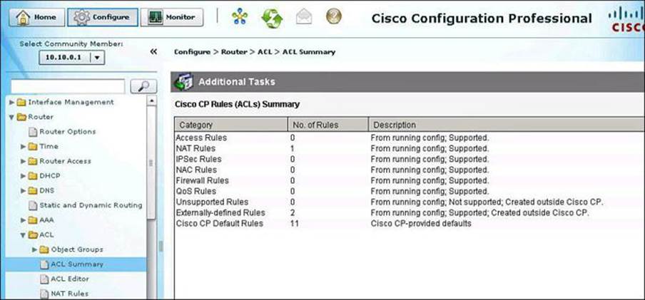
Figure 8-15. CCP ACL Summary
ACL Configuration Scenario Using CCP
To demonstrate the configuration of ACLs using CCP and the router CLI, we will step through the configuration scenario depicted in Figure 8-16. In this example, we will configure an outbound policy for the internal network, allowing only certain applications and protocols to originate traffic from the inside network.
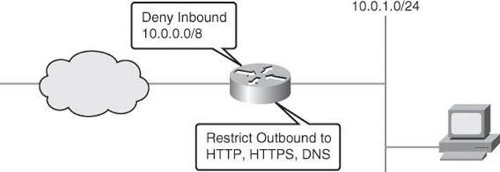
Figure 8-16. ACL Configuration Scenario
The configuration steps are as follows:
Step 1. Configure the ACL.
Step 2. Apply the ACL to interfaces.
Step 3. Verify and monitor the ACL.
ACL Editor
The ACL Editor is most commonly used to define the traffic that you want to permit or deny entry to your LAN or exit from your LAN, but ACLs can be used for other purposes as well, such as identifying traffic for NAT or for encryption.
The upper portion of the ACL Editor window, shown in Figure 8-17, lists the access rules that have been configured on this router. The lower portion of the window lists the rule entries associated with the selected rule. A rule entry consists of criteria that incoming or outgoing traffic is compared against, and the action to take on traffic matching the criteria. If traffic does not match the criteria of any of the entries in this box, it is dropped.
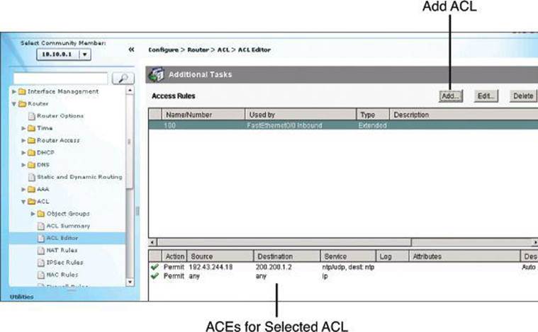
Figure 8-17. ACL Editor
To add an ACL, click the Add button in the top-right corner of the window. This opens the Add a Rule dialog box, discussed in the following section.
Adding Rules
The Add a Rule dialog box, shown in Figure 8-18, lets you add a rule. (A similar dialog box, Edit a Rule, is displayed if you select a rule in the Access Rules pane and click Edit.) In the Add a Rule dialog box, you can define a name and add a description for the rule; add, change, reorder, or delete rule entries (also known as access control entries, or ACEs); and associate the rule to an interface.
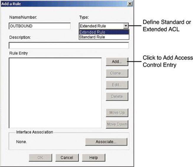
Figure 8-18. Adding a Rule with CCP
The Rule Entry pane shows the entries that make up the rule. You can add, edit, and delete entries by using the buttons to the right of the pane. You can also reorder entries to change the order in which they are evaluated. Observe the following guidelines when creating rule entries:
• There must be at least one permit statement in the list; otherwise, all traffic will be denied.
• A permit all or deny all entry in the list must be the last entry. Remember, a default deny all entry is implicit and will not show in the list.
• Standard entries and extended entries cannot be mixed in the same rule.
• No duplicate entries can exist in the same rule.
Applying the log Keyword on Explicit permit or deny ip any any
The log keyword on the final permit ip any any can prove useful for testing valid configurations. After the testing period is over, you can apply the log keyword, changing the permit ip any any log to a deny ip any any log. This will still allow you to log the data required to characterize the threat(s) while still blocking the traffic.
ACEs can be added by clicking the Add button in the Rule Entry section of the dialog box.
The Add an Extended Rule Entry dialog box, shown in Figure 8-19, lets you configure the logic of the specific ACE. An extended rule entry allows you to permit or deny traffic based on its source and destination and on the protocol and service specified in the packet. In this dialog box you will complete the following sections:
• Action: Select the action you want the router to take when a packet matches the criteria in the rule entry. The choices are Permit and Deny.
• Description: Add a description for the ACE.
• Source Host/Network: Specify the source IP address criteria that the traffic must match. The fields in this area of the dialog box change based on the value of the Type field. They are IP Address, Wildcard Mask, Hostname, or Network Object Group.
• Destination Host/Network: Specify the source IP address criteria that the traffic must match. The fields and information to complete are similar to those of the Source Host/Network section, but using the components to match a destination address.
• Protocol and Service: Select the protocol and service, if applicable, that you want the entry to apply to. The information that you provide differs from protocol to protocol. Click the protocol to see what information you need to provide. For TCP and UDP, you can use logical operators such as these in the Service field:
• =: The rule entry applies to the value that you enter in the field to the right.
• !=: The rule entry applies to any value except the one that you enter in the field to the right.
• <: The rule entry applies to all port numbers lower than the number you enter.
• >: The rule entry applies to all port numbers higher than the number you enter.
• Range: The entry applies to the range of port numbers that you specify in the fields to the right
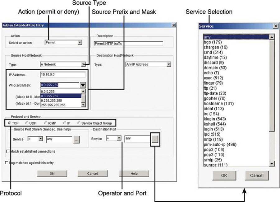
Figure 8-19. Adding an Extended Rule
If you do not remember the name or number, click the ... button and select the value you want from the Service dialog box.
Associating Rules with Interfaces
ACLs and other rules, by themselves, do nothing. You must apply them to interfaces and other router components. To apply an ACL to an interface, select a rule and click the Associate button to select the interface and direction in the Associate with an Interface dialog box, as shown inFigure 8-20. If the Associate button is not enabled, you can associate the rule with an interface by double-clicking the interface in the Interfaces and Connections window and using the Associate tab. The following are the options:
• Select an Interface: Select the interface to which you want this rule to apply.
• Specify a Direction: If you want the router to check ingress packets arriving at the interface, click Inbound. The router checks for a match with the rule before routing it; the router accepts or drops the packet based on whether the rule states permit or deny. If you want the router to match egress packets, click Outbound.
Notice in Figure 8-20 how important it is to use the correct terminology. In the example, the ACL is called OUTBOUND, as it is aimed at filtering traffic originating on the internal network on its way to external destinations. The ACL is applied inbound to the FastEthernet0/1.4 interface because it will match ingress traffic on the interface, on its way out to the external network.
• If another rule is already associated with the interface: If an information box appears that states that another access rule is associated with the interface and direction you specified, you either can cancel the operation or can continue by appending the rule entries to the rule that is already applied to the interface or by disassociating the rule with the interface and associating the new rule.
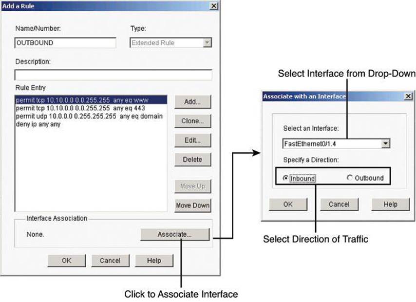
Figure 8-20. Associating Rules with Interfaces
Enabling Logging with CCP
Activity on your access control rules is monitored through the creation of log entries. If logging is enabled on the router, whenever an access rule that is configured to generate log entries is invoked—for example, if a connection is attempted from a denied IP address—then a log entry is generated and can be viewed in Monitor mode.
The first step to viewing firewall activity is to enable logging on the router. To enable logging, follow these steps:
Step 1. From the toolbar, choose Configure > Router > Logging to open the Logging dialog box, shown in Figure 8-21.
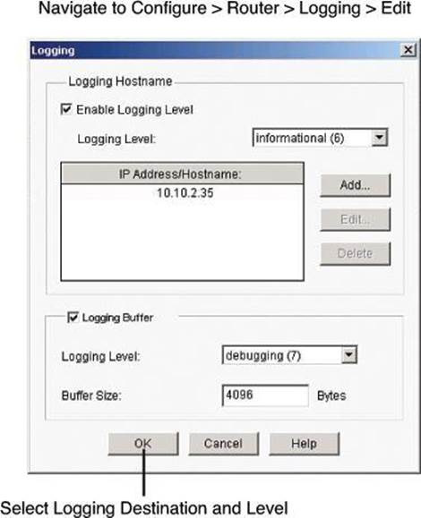
Figure 8-21. Enabling Logging
Step 2. Click Edit.
Step 3. In the Syslog window that just opened, check the Logging to Buffer check box.
In addition to enabling logging, you must identify the access rules that you want to generate log entries. To configure access rules for generating log entries:
Step 1. From the toolbar, choose Configure > Router > ACL.
Step 2. Click ACL Editor. Each access rule appears in the upper table on the right side of the screen, as shown in Figure 8-17. The lower table shows the specific source and destination IP addresses and the services that are permitted or denied by the rule.
Step 3. In the upper table, choose the rule that you want to modify and click Edit. The Edit a Rule dialog box appears.
Step 4. The Rule Entry field shows each of the source IP/destination IP/service combinations that are permitted or denied by the rule. Click the rule entry that you want to configure to generate log entries, and click Edit.
Step 5. In the Edit an Extended Rule Entry dialog box, check the Log Matches Against this Entry check box, as shown in Figure 8-22.
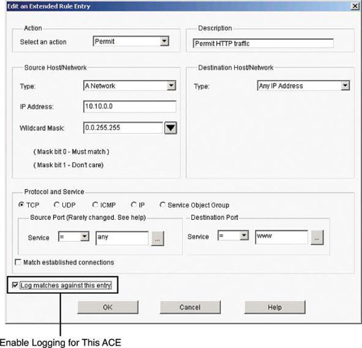
Figure 8-22. Selecting ACEs that Will Generate Log Entries
Step 6. Click OK to close the dialog boxes that are open. The rule entry that you just modified will now generate log entries whenever a connection is attempted from the IP address range and services that define the rule entry.
Step 7. Repeat Step 4 through Step 6 for each rule entry that you want to configure to generate log entries.
Monitoring ACLs with CCP
Once your logging configuration is complete, choose Monitor > Router > Logging and select the Syslog tab in the Logging dialog box, as shown in Figure 8-23. The table at the bottom shows each generated router log entry, including the time and the reason that the log entry was generated. For ACL log entries, be sure to select at least Informational from the Select a Logging Level to View drop-down menu. Notice that the table is not automatically refreshed or cleared; you need to click the Update button or the Clear button to update the view. The Search button is also important, because this table shows all syslog messages, not only those related to ACLs from the security perspective.
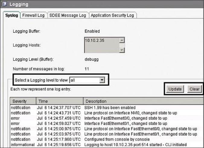
Figure 8-23. Using CCP to View Log Entries
The Firewall Log tab of the Logging dialog box, shown in Figure 8-24, also allows you to see logged ACEs, this time from the security perspective. The log entries shown in the top part of this tab are determined by log messages generated by the firewall. The Number of Attempts Denied by Firewall entry shows the number of connection attempts rejected by the firewall. The top-attacks table below the View drop-down menu displays the top attack entries. For ACLs, traffic matching a deny entry is considered an attack from the perspective of the firewall.
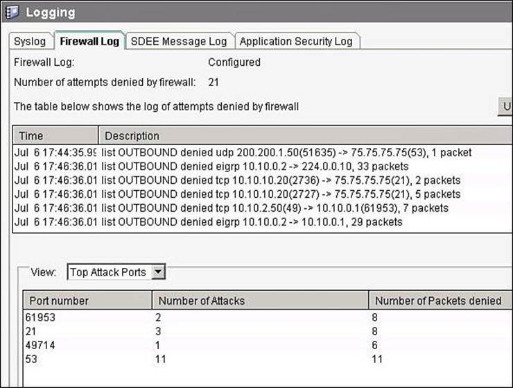
Figure 8-24. Logged ACE Generated by the Firewall Entry
Note
Logged ACLs will display events on the Firewall Log tab even if a zone-based firewall is not configured on the router.
Configuring an Object Group with CCP
You can create two types of ACL object groups:
• Network object groups: Can contain hostnames, host IP addresses, subnet masks, range of IP addresses, and other existing network object groups
• Service object groups: Can contain top-level protocols, such as TCP, UDP, and TCP-UDP; ICMP types; source and destination protocol ports; and other existing service object groups
Figure 8-25 illustrates an example of the creation of a network object group, the steps for which follow:
Step 1. Choose Configure > Router > ACL > Object Groups > Network Object Groups to open the Network Object Group summary page.
Step 2. Click Create to open the Create Network Object Group dialog box.
Step 3. Enter the group name and description, specify the parameters in the Network Object Group Members area, and then click Add. The parameters that you entered in the left pane are added to the right pane.
Step 4. Click OK to send the configured group information to the router.
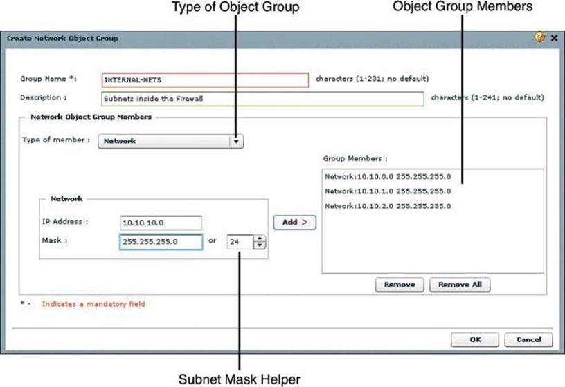
Figure 8-25. Configuring an Object Group Using CCP
Example 8-8 shows the CLI equivalent of the configuration done in Figure 8-25.
Example 8-8. Configuring an Object Group in the CLI
Router# config t
Router(config)# object-group network INTERNAL-NETS
Router(config-network-group)# description Subnets inside the Firewall
Router(config-network-group)# 10.10.0.0 255.255.255.0
Router(config-network-group)# 10.10.1.0 255.255.255.0
Router(config-network-group)# 10.10.2.0 255.255.255.0
Router(config-network-group)# 10.10.10.0 255.255.255.0
After you create network object groups and/or service object groups, you can create an ACL that can permit or deny traffic to these object groups, as shown in Figure 8-26.
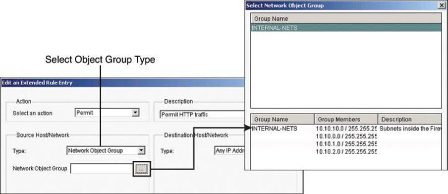
Figure 8-26. Assigning Object Groups to ACLs
Use this procedure to create an ACL that can permit or deny traffic to the configured object groups.
Step 1. Choose Configure > Router > ACL > ACL Editor to open the Additional Task Rules dialog box.
Step 2. Click Add to open the Add a Rule dialog box.
Step 3. Add a name and description for the rule in the appropriate fields, and then click Add to open the Add an Extended Rule Entry dialog box.
Step 4. From the Action field, choose the action you want to configure. The options are Permit and Deny.
Step 5. If you want to use object groups as an ACL source, from the Source Host/Network pane, do the following:
• Choose Network Object Group from the Type field.
• Click the ... (more) button—located beside the Network Object Group field—to open the Select Network Object Group dialog box.
• From the Select Network Object Group dialog box, select the network object group, and then click OK.
Step 6. If you want to use an object group as an ACL destination, from the Destination Host/Network pane, do the following:
• Choose Network Object Group from the Type field.
• Click the ... (more) button—located beside the Network Object Group field—to open the Select Network Object Group dialog box.
• From the Select Network Object Group dialog box, select the network object group, and then click OK.
Step 7. If you want to use an object group as an ACL protocol and port, from the Protocol and Service pane, do the following:
• Click the Service Object Group radio button.
• Click the ... (more) button—located beside the Service Object Group field—to open the Select Service Object Group dialog box.
• From the Select Service Object Group dialog box, select the service object group, and then click OK.
Step 8. Click OK in the Add an Extended Rule Entry dialog box.
Using ACLs in IPv6 Environments
Packet filtering in IPv6 is similar to packet filtering in IPv4. A strategy to prevent common attacks between the two protocol stacks, such as reconnaissance and spoofing attacks, typically starts with ACLs trying to match malicious traffic.
IPv6-specific attacks, such as the one depicted in Figure 8-27, require targeted filtering and IPv6-aware ACLs. IPv6 ACLs can help mitigate the following threats, among others:
• Header extension threats; for instance, amplification attacks based on Routing Header (RH 0)
• Threats based on misuse and abuse of IPv6 ICMP
• Reconnaissance based on multicast IPv6 addresses
• Threats that exploit tunneling solutions such as those used in IPv6 migration environments
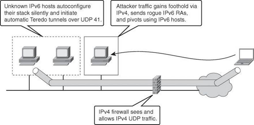
Figure 8-27. Examples of IPv6 Potential Attacks
Some threats require a combined approach using both protocol stacks, specifically those that exploit dual-stack environments. The scenario in Figure 8-27 depicts a Teredo tunnel launched from hosts that have been compromised via IPv6 but use IPv4 tunnels. Infrastructure filtering and firewalling for IPv4 would mitigate and contain the IPv6 threat.
The standard ACL functionality in IPv6 is similar to standard ACLs in IPv4. ACLs determine which traffic is blocked and which traffic is forwarded at router interfaces and allow filtering based on source and destination addresses and some Layer 4 information, inbound and outbound to a specific interface. Each ACL has an implicit deny statement at the end. IPv6 ACLs are defined and their deny and permit conditions are set using the ipv6 access-list command with the deny and permit keywords in global configuration mode. An empty ACL means that traffic is allowed. Reflexive ACLs and time-based ACLs are also available in IPv6. An IPv6 ACL can match the following IPv6 headers:
• routing: Matches any route header
• mobility: Matches any mobility header
• dest-option-type: Matches any destination option header
• auth: Matches IPsec’s AH
• undetermined-transport: Matches any packet whose Layer 4 protocol cannot be determined (fragmented or unknown extension header) (available only with the deny command)
Each IPv6 ACL contains implicit permit rules to enable IPv6 neighbor discovery, in addition to the traditional rule that implements a default deny policy. The resulting implicit rules for IPv6 ACLs are shown in Example 8-9.
Example 8-9. IPv6 ACL Implicit Entries
permit icmp any any nd-na
permit icmp any any nd-na
deny ipv6 any any
The IPv6 neighbor discovery process makes use of the IPv6 network layer service. Therefore, by default, IPv6 ACLs implicitly allow IPv6 neighbor discovery packets to be sent and received on an interface. Neighbor discovery is similar to ARP for IPv4.
To add some context to these implicit rules, they implement what IPv4 implemented for the Address Resolution Protocol (ARP). In IPv4, ARP, which is equivalent to the IPv6 neighbor discovery process, makes use of a separate data link layer protocol. Therefore, by default, IPv4 ACLs implicitly allow ARP packets to be sent and received on an interface. The same is true for neighbor discovery in IPv6.
The user can override these rules by placing a deny ipv6 any any statement within an ACL.
Historically, in IPv4, administrators add the implicit deny any rule, along with the log keyword, to the end of an ACL. This is effective for monitoring and auditing ACLs, and also for logging denied packets. Doing the same in IPv6 requires adding all three implicit rules. Not doing so would result in neighbor discovery issues. In the example in Figure 8-28, a single deny ipv6 any any line is added to log denied packets. The two implicit rules that allow neighbor discovery in Example 8-9 are never evaluated, as all traffic is denied before it reaches the neighbor discovery rules. The solution to this problem is to explicitly add all three implicit lines, in the right order, at the end of your ACLs.
Figure 8-28 shows the topology we will use for the following named IPv6 ACL example.
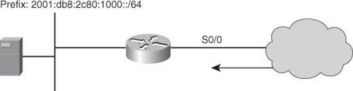
Figure 8-28. Example of IPv6 ACLs
The syntax of IPv6 ACLs is similar to that of IPv4 ACLs. However, this time, the ACEs match IPv6 sources, destinations, and ports. Also notice that wildcard masks are no longer used, and the used of the /x nomenclature is pervasive across the syntax. One noticeable difference with IPv4 ACL commands is the use of the ipv6 traffic filter command to apply the ACL to interfaces, instead of the traditional ip access-group command used in IPv4 ACLs. Proper planning is required in using masks to match summarizable address blocks, given the more complex structure of IPv6 IP addresses.
The following is the syntax of IPv6 ACLs. Refer to Cisco IOS documentation for the detailed information:
permit protocol {source-ipv6-prefix/prefix-length | any | host
source-ipv6-address | auth} [operator [port-number]] {destination-
ipv6-prefix/prefix-length | any | host destination-ipv6- address |
auth} [operator [port-number]] [dest-option-type [doh-number | doh-
type]] [dscp value] [flow-label value] [fragments] [log] [log-
input] [mobility] [mobility-type [mh-number | mh-type]] [reflect
name [timeout value]] [routing] [routing-type routing-number]
[sequence value] [time-range name]
or
permit protocol {source-ipv6-prefix/prefix-length | any | host
source-ipv6-address | auth} [operator [port-number]] {destination-
ipv6-prefix/prefix-length | any | host destination-ipv6- address |
auth} [operator [port-number]] [dest-option-type [doh-number | doh-
type]] [dscp value] [flow-label value] [fragments] [log] [log-
input] [mobility] [mobility-type [mh-number | mh-type]][routing]
[routing-type routing-number] [sequence value] [time-range
name][undetermined-transport]
Example 8-10 illustrates an IPv6 ACL for ICMP that implements RFC 4890, which describes recommendations for filtering ICMPv6 messages in firewalls.
In networks supporting IPv6, ICMPv6 plays a fundamental role with a large number of functions, and a correspondingly large number of message types and options. ICMPv6 is essential to the functioning of IPv6, but there are a number of security risks associated with uncontrolled forwarding of ICMPv6 messages. Filtering strategies designed for the corresponding protocol, ICMP, in IPv4 networks are not directly applicable, because these strategies are intended to accommodate a useful auxiliary protocol that may not be required for correct functioning.
Example 8-10 illustrates a restrictive policy in which the required and necessary ICMPv6 message types are allowed and any unmatched types are denied. This is not a guarantee of protection against ICMPv6-based attacks, but it is a good starting point.
Example 8-10. RFC 4890 ICMP ACL
ipv6 access-list RFC4890
permit icmp any any echo-reply permit icmp any any echo-request permit icmp any any
1 3
permit icmp any any 1 4
permit icmp any any packet-too-big permit icmp any any time-exceeded permit icmp any
any parameter-problem permit icmp any any mld-query
permit icmp any any mld-reduction permit icmp any any mld-report permit icmp any any
nd-na
permit icmp any any nd-ns
permit icmp any any router-solicitation
Summary
This chapter presented the use cases and benefits of ACLs in general. It described the building blocks and operational framework of ACLs. Prior to digging into ACLs, we reviewed how summarizable address blocks in the context of CIDR and VLSM environments work, and we then evaluated how ACL wildcard masks allow for threat mitigation in those environments.
This chapter also presented design considerations when deploying ACLs in general and demonstrated the use of Cisco Configuration Professional and the CLI to deploy and verify a threat containment strategy using ACLs and to correlate ACL log and alarm information in order to monitor their impact and effectiveness. You learned how to configure object groups to streamline the implementation of ACLs for threat control. This chapter finished by showing you how to configure ACLs in IPv6 environments, highlighting the operational differences with IPv4 ACLs.
References
For additional information, refer to these Cisco.com resources:
“Identifying Incidents Using Firewall and Cisco IOS Router Syslog Events,” http://www.cisco.com/web/about/security/intelligence/identify-incidents-via-syslog.html
“IP Access List Entry Sequence Numbering,” http://www.cisco.com/en/US/docs/ios/12_2s/feature/guide/fsaclseq.html
“Understanding Access Control List Logging,” http://www.cisco.com/web/about/security/intelligence/acl-logging.html
Review Questions
Use the questions here to review what you learned in this chapter. The correct answers are found in the Appendix, “Answers to Chapter Review Questions.”
1. Which type of threat cannot be mitigated using ACLs?
a. Malicious payload
b. DoS TCP SYN attack
c. ICMP message filtering
d. Source IP address spoofing
2. What is the range of ACL numbers for a standard access list? (Choose two.)
a. 100–199
b. 1–99
c. 1300–1999
d. 0–99
3. Which wildcard mask would match for IP subnets 172.30.16.0/24 to 172.30.31.0/24?
a. 0.0.31.255
b. 0.0.0.255
c. 0.0.255.255
d. 0.0.15.255
4. Which of the following ACLs would allow users to access their Post Office Protocol server?
a. access-list 101 permit tcp any any eq 25
b. access-list 101 permit tcp any eq 25 any
c. access-list 101 permit tcp any eq 110 any
d. access-list 101 permit tcp any any eq 110
5. Which of the following is a caveat regarding ACLs?
a. Standard ACLs must be used to implement security policies.
b. Beware of the explicit deny all at the bottom of ACLs.
c. Place less specific statements higher in ACLs.
d. Ensure that statements at the top of ACLs do not negate statements found lower in the list.
6. Which of the following are rules that can be configured by Cisco Configuration Professional? (Choose all that apply.)
a. NAT rules
b. Firewall rules
c. Unsupported rules
d. Sysopt rules
7. Using which keyword in the access-list command is a best practice method for understanding what is happening to traffic as it passes through the firewall?
a. established
b. eq
c. log
d. matches
8. Which of the following are benefits of using ACL object groups? (Choose all that apply.)
a. Optimized logging
b. Increased performance
c. Reduced storage
d. Separates ownership of the components of an ACE
9. Using which keyword in the access-list command designates that the packet is a response to an outbound initiated session?
a. established
b. eq
c. log
d. matches
10. Which of the following are implicit IPv6 ACLs entries? (Choose all that apply.)
a. permit icmp any any nd-na
b. deny ipv6 any any
c. permit icmp any any nd-ns
d. deny ipv6 icmp any any