EnCase Computer Forensics (2012)
Chapter 4
Acquiring Digital Evidence
EnCE Exam Topics Covered in This Chapter:
· Creating EnCase DOS boot disks
· Booting computers using EnCase DOS boot disks
· Drive-to-drive acquisitions
· Network and parallel cable acquisitions
· FastBloc/Tableau acquisitions
· FastBloc SE acquisitions
· LinEn acquisitions
· Enterprise and FIM acquisitions
· EnCase Portable acquisitions
Following best forensics practices, I typically conduct examinations or analyses on copies of the original evidence. In this manner, I preserve the original, protecting it from alteration or corruption. The copy of the original evidence is more commonly called an image. For this image to be a copy and the legal equivalent of the original, it must represent a duplicate image of the original. Thus, every 1 and 0 on the original must be replicated on the copy or image. In this chapter, I’ll discuss the various methods of acquiring the original evidence and rendering from it an image upon which you can conduct your forensic examinations.
In the previous chapter, I discussed first-response issues, from preparing yourself and equipment to processing the scene. During that discussion, I made several references to different methods of acquiring digital evidence, both in the field and at the lab. EnCase provides many options for acquiring digital evidence, some of which are available in all models of EnCase and some are available only in the Enterprise and FIM versions.
Each case is unique and presents its own set of challenges and obstacles. No doubt you will use one or two of your favorite acquisition methods for most of your casework. You should, however, be familiar with the other options or methods to use when circumstances force you to use another method to get that image.
I’ll begin with the basics: creating boot disks in either floppy or CD format. Using those boot disks, you can boot a computer into a DOS mode that is forensically sound. From there you acquire media using the drive-to-drive, network cable, and parallel cable methods. While these are legacy methods, you can still encounter older systems where such techniques become the best option.
Beginning with EnCase version 5, a Linux-based utility has been included in the EnCase distribution. This utility is called Linux EnCase (LinEn). It provides similar functionality to the DOS boot; however, LinEn runs under Linux, which means that instead of a 16-bit operating system, as with DOS, you are running under a full 32-bit operating system. Thus, you have all the features of the traditional EnCase for DOS with the added bonus of the Linux command-line features and much faster performance.
Starting with EnCase 6, the DOS version of EnCase is no longer available (because floppy disks are going the way of the dinosaurs). Remaining in its place, however, is LinEn. Even though floppy disks are fading away, there are still plenty of legacy boxes out there for which a floppy boot disk may be needed (these systems were made in the era when CD-ROM drives were an expensive option). A good examiner should know how to create a floppy disk using EnCase version 7, but with an earlier DOS version of EnCase as the executable.
FastBloc is a hardware write-blocking device developed for use with EnCase. It has undergone an evolution that now encompasses several hardware models. FastBloc hardware devices are no longer available and have been replaced by the Tableau line of hardware write blockers, which came about when Guidance Software acquired the assets of Tableau, LLC. I’ll discuss how it can be used to acquire hard drives in Window, DOS, and LinEn.
With EnCase 7, FastBloc Software Edition (dubbed FastBloc SE), formerly available as an added cost option, is now included as part of the basic software feature set. With FastBloc SE, you can write block Plug and Play USB, FireWire, and SCSI devices easily. These options appear in the Tools menu.
EnCase Portable is a relatively new tool that allows for the collection of data in the field. Among its collection tool sets is the ability to make acquisitions. We’ll cover the acquisition capabilities of this tool.
Finally, I’ll discuss the feature set of the Enterprise and FIM versions of EnCase, with their unique ability to acquire media over a network while maintaining an extremely secure environment known as SAFE (Secure Authentication for EnCase). As an added feature, these versions can capture volatile system-state data, thus making them valuable tools for live analysis and live acquisitions.
Creating EnCase Forensic Boot Disks
![]()
Initially, I’ll focus on creating EnCase DOS boot disks using EnCase 5 (or older). I’ll switch to EnCase 7 when the new features of that version merge into the process.
The purpose of the forensic boot disk is to boot the computer and load an operating system in a forensically sound manner so that the evidentiary media is not changed. A normal DOS boot disk will make calls to the C: drive primarily via COMMAND.COM but also with IO.SYS. Figure 4-1 shows COMMAND.COM making a call to the C: drive. Also, it will attempt to load DRVSPACE.BIN (disk compression software) if present. An EnCase forensic boot disk will be modified so that any calls to the hard drive (C:) are redirected to the floppy drive (A:). EnCase accomplishes this by modifying the COMMAND.COM and IO.SYS files when creating or converting to forensic boot disks, as shown in Figure 4-2. If DRVSPACE.BIN is found, it will be deleted to prevent it from mounting the drive. In this manner, an EnCase forensic boot disk can boot a computer to a forensically sound, safe version of DOS.
Figure 4-1: Normal Windows start-up disk with COMMAND.COM making a call to the C:
![]()
Figure 4-2: Windows start-up disk modified by EnCase with COMMAND.COM making same call to A:
![]()
EnCase can update an existing boot disk running on Windows 2000/XP/2003/Vista/7. EnCase can convert an existing start-up disk to a forensic boot floppy (as shown in Figure 4-2) under those same versions of Windows. Under any version of Windows thus far referenced, it can create a boot disk from an evidence file or boot disk image. During this process, files such as the drivers or the updated version of EN.EXE can be added. Version 5 can also create a bootable CD from an ISO image with the same ability to add files as it is rendered to CD.
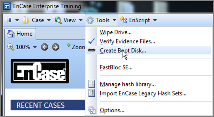
All this functionality is available by choosing Tools > Create Boot Disk, as shown in Figure 4-3. In the resulting window, choose A to create a floppy, or choose ISO Image to create a CD (see Figure 4-4). If you select A, the next choices will be Update Existing Boot Floppy, Overwrite Diskette With A Boot Floppy Base Image, or Change From A System Diskette To A Boot Floppy, as shown in Figure 4-5.
Figure 4-3: Creating a boot disk using the Tools menu in EnCase 5
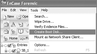
Figure 4-4: Choose a floppy (A) or CD (ISO image).
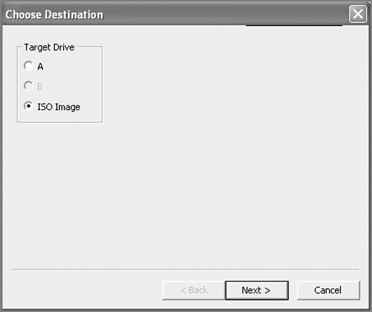
Figure 4-5: Forensic boot floppy formatting options
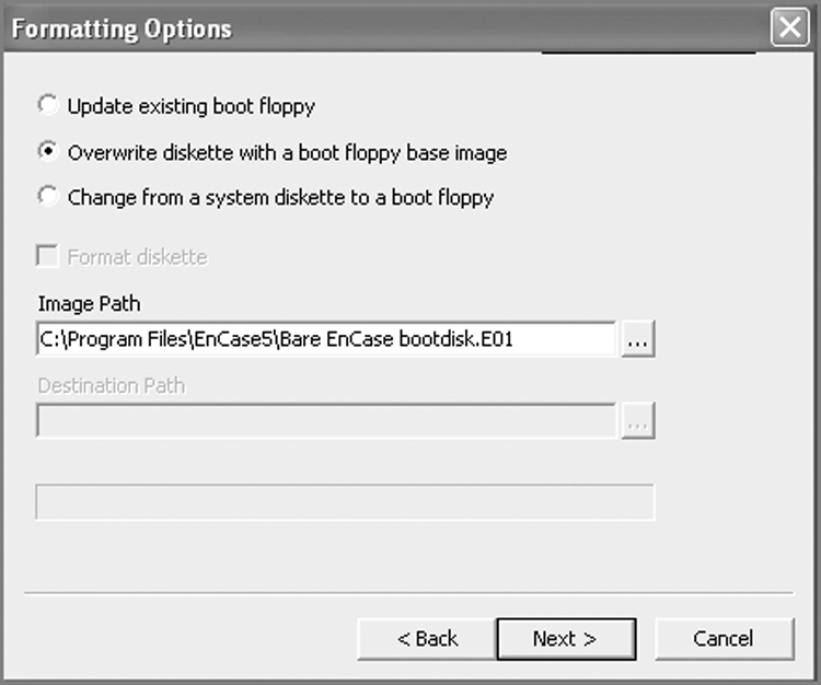
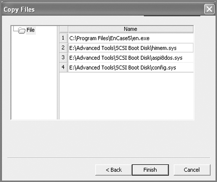
With the first option (Update Existing Boot Floppy), you are given the opportunity to add or replace files on an existing boot floppy, such as drivers or the latest version of EN.EXE. With the second option (Overwrite Diskette With A Boot Floppy Base Image), the floppy in your drive is overwritten with the boot floppy image of your choice. Many examiners keep custom boot floppy images on hand for a variety of specialized tasks. The third option (Change From A System Diskette To A Boot Floppy) allows the user to take a regular start-up floppy (one that is not forensically sound) and convert it to a forensic boot disk. The files (COMMAND.COM and IO.SYS) are modified (DRVSPACE.BIN, if found, is deleted) as described earlier and as shown in Figures 4-1 and 4-2. All three options provide, as a final step, the option to add or replace files (see Figure 4-6).
Figure 4-6: All three formatting options provide the option to add or replace files; in this example, EN.EXE is updated, and SCSI drivers are added.
The foregoing steps were demonstrated using EnCase 5, which was the last version of EnCase to ship with en.exe, which is the DOS version of the EnCase acquisition tool. EnCase 6, and now EnCase 7, provides a similar mechanism for creating a boot floppy; however, en.exe will not be available in the program files that ship with EnCase, and thus you won’t be able to use EnCase to update the en.exe file. With later versions of EnCase (after 5), you’ll need to use an image of a boot floppy, available from Guidance Software’s support portal in the Boot Disks section of the Downloads tab. Figure 4-7 shows this feature located on the EnCase 7 Tools drop-down menu.
Figure 4-7: The feature to create a boot floppy is found on the drop-down menu under Tools on the toolbar.
Booting a Computer Using the EnCase Boot Disk
Despite advances in technologies that allow acquisitions to occur in the Windows environment using FastBloc, Tableau, or other write-blocking methods, you’ll sometimes still need a DOS boot. To make matters worse, you have to use the suspect machine to host the boot. The situations requiring this method include the following:
· Geometry mismatches between the host BIOS (legacy) and your exam machine BIOS (the latest and greatest)
· Suspect hard drive that is “married” to the host motherboard via a security scheme
· Hard drive that is part of a hardware RAID, particularly when reconstructing the RAID from individual hard drives, in which it is a RAID scheme that is not supported by EnCase
Seeing Invisible HPA and DCO Data
You may also encounter a Host Protected Area (HPA) or a Device Configuration Overlay (DCO). HPA was introduced with the ATA-4 standard. Its purpose is to create a place at the end of the drive for vendors to store information (recovery, security, registration, and so on) that is invisible to the BIOS and hence protected from user access or erasure (format, and so on). DCO was introduced with ATA-6 and was initially intended as a means of limiting the apparent capacity of a drive. DCO space also appears at the end of the drive and is not seen by the BIOS.
Because neither HPA nor DCO areas can be seen by the BIOS and both can contain hidden data, one way to access this data is via Direct ATA. This method is available using EnCase for DOS on a forensic boot disk. In Direct ATA mode, EnCase communicates directly with the ATA controller and is able to access all sectors, including HPA and DCO sectors that weren’t seen or accessed by the BIOS.
HPA or DCO?
When trying to determine whether you are seeing all the sectors in a drive, you’ll often look to the sectors reported by the manufacturer. In some cases, you can miss sectors this way. Recently while imaging a Western Digital WD800 80 GB drive, I noted that the manufacturer reported on the drive label that the drive contained 156,250,000 LBA sectors. While looking at the physical drive attached to FastBloc FE in Windows, EnCase was reporting all 156,250,000 sectors as seen by the BIOS, which matches the sectors reported by the manufacturer. Should I conclude that there is no HPA or DCO in place?
Your first clue to this problem typically occurs when you connect your target drive to FastBloc or Tableau in Windows and note that the total number of sectors on the drive, as reported by EnCase, is lower than the number of sectors known to be available on the drive (Total LBA Sectors). Instead of relying upon the hard drive label, you should consult the manufacturer’s website for more accurate technical specifications for the hard drive. Because best forensic practices call for accounting for all sectors on a drive, this should be standard practice with all drives. When EnCase is reporting fewer sectors than the manufacturer, you should suspect HPA or DCO and investigate further. EnCase for DOS Direct ATA’s access feature is one method to reconcile the difference and obtain all the sectors on the drive, albeit a legacy method.
![]()
You can use LinEn—EnCase running under Linux or the FastBloc SE module—in lieu of EnCase for DOS for detecting and accessing HPAs and DCOs. I’ll cover its feature set later in this chapter.
Other Reasons for Using a DOS Boot
Sometimes, for other reasons (legacy equipment, HPA, DCO, and so on), you may opt for a DOS boot when the storage drive is on your examination machine. Because this is a known, safe, forensic environment, it is far better than using the suspect’s computer. Even so, you still must control the boot process so that you boot from your forensic boot disk and not the target drive.
When booting with the suspect machine, there is always risk since it is an unknown environment. When you have no other good option, you must proceed carefully. If you make an error or omission along the way, you risk altering your evidence drive because of an accidental boot of that drive. Your goal is to control and test the boot process so that you can boot the machine with your known safe forensic boot disk, and at the same time ensure that your target evidence drive is safe from calls and writes during the boot.
Chapter 1 gave you a solid understanding of the boot process, and Chapter 3 explained when and how you shut down a system. It is now time to put that knowledge to work. The following steps provide a framework for safe forensic booting of the suspect machine. Keep in mind, however, that nothing is guaranteed. Even if you are DOS-booting from your examination machine, you should still follow the basic format: configure the boot process, test, confirm, and proceed carefully. Always be prepared for the unexpected by having your hand on the power cord, ready to pull it immediately if something goes wrong.
Steps for Using a DOS Boot
To use a DOS boot, follow these steps:
1. Make certain that the target computer is powered off. Refer to your own policies and the guidelines in Chapter 3 with regard to appropriate shutdown procedures, which depend on the operating system, applications, function, and environment.
2. Disconnect the power cord from the back of the computer, and open the case. Inspect the interior for hard drives and connections, noting in particular anything unusual. It is common to find disconnected hard drives inside as well as additional connected hard drives mounted in any available space.
3. Disconnect both the power cable and data cable from any connected hard drive. If more than one hard drive exists, label the data connections before disconnecting them so they are reconnected properly when the time comes to do so.
4. Insert the forensic boot disk into the drive. If you are booting with a CD, use a paper clip to open the drive tray first. If you’re not familiar with this technique, there is a tiny hole in the face of most CD/DVD drives. Pressing a straightened paper clip into the hole opens the tray when the unit has no power.
5. With all hard drives disconnected and your boot disk inserted, reconnect the power cord, and start the computer. Immediately be prepared to enter the Setup routine, which occurs around the time you first see something on the screen. Typically you will see a message on the screen such as “To Enter Setup Press F2.” Often the key you need to press to enter Setup is displayed, but in some systems this is hidden from the user. When this happens, you can refer to the system manual, if available, or you can try the more common keys, which are as follows:
· F1 (for IBMs and many clones).
· F2, F12, or Delete (common with many Gateways, Dells, HPs, and other clones).
· F10 (common with Compaqs).
· Ctrl+Alt+Esc or Ctrl+Alt+Enter (if the previous keys don’t work).
· Sometimes removing all bootable media, including your forensic boot disk, will force a system to enter Setup or provide a prompt that reveals the elusive key that accesses Setup.
6. Once inside Setup, locate the boot settings, specifically, the boot order. This is the process you seek to control! Before making changes, record the current order in your notes. Set the order so that your forensic boot disk device (floppy or CD) appears before the target hard drive.
7. Save your changes as you exit Setup. If you don’t save the changes, the old settings will apply.
8. It is now time to test the boot environment to make certain the settings you configured work and that the forensic boot devices also work. At this point, your target hard drive(s) should still be disconnected. Start the computer, and make certain your boot device works. If so, power down the computer, and disconnect the power cord.
9. If you are going to be using a hard drive on the target machine to store the image, you should connect it and again test your boot environment to see whether the system attempts to boot to the hard drive. If all is well and your system boots to the forensic boot disk, again, power down your system and disconnect the power cord.
10. If all is safe at this stage, it is time to reconnect your target hard drive. Then double-check that your forensic boot disk is still inserted. Reconnect the power cord, and keep your hand on it where it connects to the case so you can abort the process if it fails. Start the system, and watch the boot process. If you followed the steps carefully and thoroughly tested your boot environment, it should boot to the forensic boot disk. If it does not, at the first sign of a problem immediately pull the power cord.
![]()
Before connecting this storage drive to your system, make sure of the following:
· The drive is formatted with FAT (DOS doesn’t recognize NTFS)
· The drive has a unique volume label to identify it later
· A directory (use DOS naming conventions) exists to store your image
Drive-to-Drive DOS Acquisition
A drive-to-drive DOS acquisition takes place entirely in DOS, and the target drive and the image storage drive are attached to the same motherboard, which is why it’s called drive-to-drive. It is a simple means of acquisition because you need to pack only an EnCase boot disk and a storage hard drive. No dongle is needed. Many examiners, having started forensics years ago when this was the standard acquisition method, still prefer it.
Drive-to-drive is a relatively fast acquisition. The speed limitation is usually imposed by the slowest component in the ATA subsystem, be it the controller, cable, configuration, or drive speed. The faster configuration will usually be master-to-master on different channels (primary and secondary) vs. master-to-slave on the same channel. If you’re providing your own cable for your storage drive, make sure it is an 80-conductor IDE cable; shorter is better. The closer you get to the 18-inch maximum length for these cables, the greater the possibility of communications errors during acquisition.
Steps for Drive-to-Drive DOS Acquisition
When conducting a drive-to-drive DOS acquisition, you should follow these steps:
1. Make sure your system is configured, tested, and ready for a safe boot to a forensic boot disk as outlined in “Booting a Computer Using the EnCase Boot Disk” earlier.
2. If you are booting using the suspect’s computer, install the storage drive on that system. If you are booting to your examination machine, install the suspect’s hard drive on that system. When doing so, keep in mind the following:
· Configure your drives so they are cabled and pinned as masters. Master-to-master data transfer will give you better performance.
· EnCase for DOS can write only to a FAT-formatted drive, so format as FAT only.
· Use a volume label name on the storage drive that uniquely identifies it in the EnCase for DOS environment. Doing so avoids confusion and mistakes that could result in imaging your storage drive onto your evidence or target drive.
· The file directory path on the storage drive that will contain the image files must already exist. Create a directory after formatting and before attaching the evidence drive to the system. In this way, you avoid accidental writes to the evidence drive.
3. With the EnCase boot disk inserted and the target and storage drives properly attached, start the computer, and carefully monitor the boot; be in a position to pull the cord from the back of the machine immediately if things go wrong.
4. When DOS boots and the A prompt appears, type en, and press Enter. EnCase for DOS will start. On the left pane you will see physical devices, and on the right pane you will see logical devices. The logical devices will be color-coded to correspond with the color-coding on the physical devices on which they are installed.
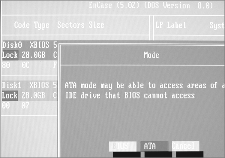
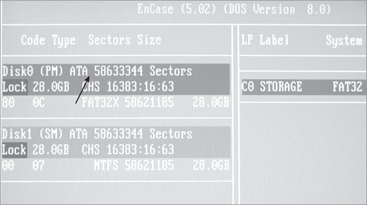
5. If you have selected a DOS boot because all sectors were not accessible through FastBloc in Windows, now is the time to change from BIOS access (default) to Direct ATA access. Do this by pressing M or by tabbing to the Mode tab. If you started with a DOS boot for other reasons, check now to make certain the sectors reported by the BIOS access match those reported by the manufacturer. If they do, you can proceed to the next step. If they don’t, as in Figure 4-8, you need to switch to the Direct ATA access using the Mode tab, as shown in Figure 4-9 and Figure 4-10.
Figure 4-8: Two Western Digital 30 GB drives. Western Digital reports these drives as having 58,633,344 LBA sectors. XBIOS is reporting only 58,621,185 sectors (see arrow). That means 12,159 sectors (6,225,408 bytes) are not being seen by the BIOS!
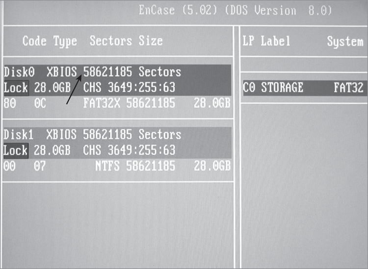
Figure 4-9: To access the hidden sectors, switch to Direct ATA access using the Mode tab.
![]()
For a logical device to appear on the right pane, it must be a partition recognized by DOS, which means only FAT partitions appear. NTFS partitions, even though they are Microsoft partitions, do not show in the right pane! Similarly, don’t expect to see Linux, Mac, or other non-DOS partitions here.
Figure 4-10: After switching to the Direct ATA access mode, all 58,633,344 sectors are visible (see arrow).
6. By default, EnCase for DOS implements a software write block on all devices, as indicated by the word Lock appearing in red next to each device. You will need to unlock your storage drive before EnCase can write to it. This is where it is important to have given a unique name to the volume so it can be unmistakably identified and unlocked. When you are certain you have identified your storage drive, unlock it by pressing L or by tabbing to the Lock tab and pressing Enter. You will be given a choice of drive letters and numbers to unlock. Once you choose your storage drive, the word Lock in red will no longer be next to your drive. Check and double-check before proceeding.
7. When you have unlocked the storage drive, press A to acquire. You will be given a choice of drives to acquire, both by letter (logical) and by number (physical). Usually you will want every sector on the drive and will choose the physical drive.
8. You will be prompted for the path on the storage drive on which to place the drive image. You must enter the path exactly as it exists on the storage drive along with the name of the file. As a safeguard, this path must already exist.
9. You are prompted for the case number; enter it, and continue to the next step.
10. You are prompted for the examiner’s name; enter your name.
11. You are prompted for an evidence number. Many naming conventions are possible. Use your lab protocol, and enter the number.
12. You are next prompted for a brief description of the evidence; enter it, and continue to the next step.
13. The system date and time appears next. If correct, press Enter. If not, enter the correct date and time. Entering the correct date and time doesn’t change your system time, but it does reflect in the acquisition information reported by EnCase as Reported Time and Actual Time.
14. The next prompt allows you to enter any notes you want.
15. You are then given the option to compress the evidence. Because compression saves you disk space (two to three times less space) but costs you more time to process the compression algorithm (up to five times as long), here is where you ask yourself whether you have more time or more disk space available to you. Because time seems to be the scarcer of the two, I rarely use compression.
16. You are next asked whether you want to generate an MD5 hash of the drive as it is acquired. It is by this process that the acquisition hash is generated that later allows you to verify that the copy you made is the same as the original. It is recommended that you always generate this value. At no time have I ever skipped this process, and I can’t conceive of a situation where I would. Nevertheless, it is optional.
17. EnCase next prompts you to provide a password. Simply pressing Enter here negates applying a password—which I recommend you do unless you have a compelling need to include a password. Keep in mind that if you apply a password and then forget or lose it, the recovery is expensive. Passwords are useful in some applications. In special master situations, an examiner can acquire the evidence, but the special master applies the password. In this manner, the examiner can acquire and retain the image, but it can be read and examined only in the presence or with the permission of the special master who holds the password. This is often done in cases in which the image contains privileged information and special protective measures must be used.
18. Your next option will be that of determining the file segment size (chunk size) of the image file. Rather than creating one massive file, the files are created in segments, or what we commonly call chunks. The smallest size is 1 MB, and the largest size is 2,000 MB (2 GB). The default of 640 MB is recommended, because a file this size fits on a CD and seven “chunks” will fit nicely on a DVD (4.7 GB).
19. Your next choice is the number of sectors to acquire. This will default to the number present on the device you are acquiring, which is almost always what you want. Sometimes, naturally, you’ll need a different number to acquire. Sometimes you have to acquire an image of a drive that has been restored onto another drive. As often happens, the drive receiving the restored image is larger than the drive image placed on it. When acquiring such a drive, you’ll want to acquire only the number of sectors reported in the image restored and not the entire drive. If you restored a 20 GB drive onto a 30 GB drive, you’ll want to acquire only the number of sectors comprising the 20 GB drive.
20. The next option was new with EnCase 5: the ability to vary the granularity of the acquisition. In prior versions, if EnCase discovered a sector with an error, the entire block of 64 sectors (32 K) was zeroed out. If only one sector was bad, 63 sectors of potentially valuable data was disregarded and counted as null. With versions 5 and 6, you can change the default of 64 sectors to 1, in powers of 2. Thus, settings can be 64, 32, 16, 8, 4, 2, or 1. If one sector is bad and the setting is 64, then all 64 sectors are zeroed out. If one sector is bad and the setting is 32, then 32 sectors are zeroed out. If one sector is bad and the setting is 1, only the bad sector is zeroed out, meaning no data is lost. It might seem that the best setting would be 1, but such granularity results in a performance hit, slowing down acquisition. Typically you use the default setting of 64 and lower it only if you encounter a drive with errors.
21. At this point, the acquisition will start. Depending on the system, the drive sizes, and the options selected, the process can take hours. A progress bar will appear, giving you a lapsed time and an approximation of the time remaining. EnCase will create files using the name you designated earlier and with extensions starting with .e01, .e02, and so on, until done. The files created will be in the chunk sizes you specified in the earlier setting, 640 MB by default. With large drives and no compression, the number of files can be significant. If 100 or more files are needed, after the .E99 extension is reached, the extension will change to .eaa, .eab, .eac, and so on. If the files needed to store the image exceed that on the current storage drive, you will be prompted for a location for additional storage. It is important to have adequate storage space formatted, ready, and mounted even if it is more than one storage drive so that it is available when EnCase needs it.
Supplemental Information About Drive-to-Drive DOS Acquisition
I cover FastBloc in detail later in this chapter. In the meantime, you need to know that Tableau bay-mounted forensics bridges can be used for drive-to-drive DOS acquisitions. The Tableau bridges all have IDE channel write-blocking function. The target or suspect hard drive can be connected to Tableau bridge and uses hardware write-blocking features to protect it from accidental writes in the event that the wrong drive is unlocked using the software write-blocking feature of EnCase for DOS. Aside from the initial connection, everything else is the same.
Thus far, the discussions have dealt with PC-based systems. If you encounter Mac hard drives, you can’t boot them with an EnCase boot disk in their host systems. Rather, you usually need to move the drive to your examination machine and acquire it as another IDE drive. (But see the sidebar “Acquiring a Mac Drive Using FireWire” for another option.) The same goes for Unix and BSD; those drives will have to be transferred to the examination computer for imaging. None of these partitions will show as logical partitions in the right pane, because DOS does not recognize them. Nevertheless, their physical drives will populate the left pane, and they can be acquired as physical drives. Later when the images are brought into EnCase for Windows, their file structures can be interpreted, mounted, and processed as with any other partition.
Dead Hard Drives Are Not Always Dead!
After a domestic-violence incident and initiation of a divorce proceeding, the soon-to-be former spouse of a network administrator walked into the office of her soon-to-be ex-husband’s supervisor. She told her husband’s supervisor that he had “trojanized” the entire network—he had captured passwords and was eavesdropping on his boss’s email account from his home machine. Among other things, she placed a hard drive on the supervisor’s desk, claiming it had been in her husband’s computer and that he had left it behind when he moved out.
The police were immediately notified, and I was called in to examine the machines in that network. I isolated the infected network segment and began the task of acquiring images of each machine for later examination. This occurred several years ago, and EnCase Enterprise and FIM as tools for capturing volatile data were not options at the time. The subsequent examination established that the various machines on that subnet either had Back Orifice currently installed or had them installed at one time. The Back Orifice server had been built on the network administrator’s workstation and had been deployed in a “dancing cat” program popular with the staff. A list of staff passwords was found, as was a similar list from the network administrator’s previous place of employment. Old habits seem to die hard!
The suspect’s home hard drive was dead. It would not spin up, and it appeared that its only use was going to be as a “bithead” paperweight. The spouse indicated her husband would experiment with hard drives, attempting to “kill” them by zapping them with high voltages. She thought he had zapped that one and that was probably the reason he had left it behind. She commented that it was a shame because she was certain that drive was in his machine when he was getting into all those email accounts.
The drive sat around for a while until one day I decided to send it out to a clean room. Before I underwent that expense, I thought I would try replacing the circuit board on the drive. With a little bit of Googling I located two identical model drives and had them shipped overnight. I took the circuit board from one and placed it on the “dead” drive. When I connected it and powered it on, the drive spun up, and the acquisition was a success.
Needless to say, the drive was loaded with emails intercepted from his boss’s account. The date and time stamps coincided with modem connection logs from the server that were tied to his telephone number.
We spent two days in court successfully defending against a motion to suppress the recovered hard drive evidence. Because it was marital property at the time, the spouse had a legal right to the hard drive and could turn it over to the police if she elected to do so. With that issue resolved, a guilty plea followed.
Even if a hard drive seems dead, there may be ways of bringing it back to life!
Acquiring a Mac Drive Using FireWire
Although you can’t use an EnCase DOS boot disk to boot a Mac, you can sometimes avoid having to remove drives to image them on another system. This is especially useful on Mac laptops where disassembly is quite a chore. The trick to use is the Mac FireWire boot mode. When you turn on a Mac, hold down the T key until you see the FireWire icon the screen. At this point, connect the Mac to your Windows forensics box via a FireWire cable. Windows can’t read the partition table and will see it only as a physical drive. EnCase, however, can see the physical drive and mount the file system. From there, it’s a simple matter to acquire, and the speed is quite respectable.
The examiner should understand that this method is not a true write-block method and only depends on the inability of Windows to recognize the partitions used by the Mac. If a Mac is an Intel-based system and is configured in a dual-boot configuration using “Boot Camp,” the Mac will have partitions that Windows will recognize and mount. In such a case, placing a Tableau FireWire write blocker between the Windows machine with EnCase and the Mac in Target mode is an option. Thus, before using a method such as described, you must be sure of what the platform is and its configuration. If in doubt, use another method.
In February 2011 Apple released Thunderbolt interface technology on all new releases of Macintosh computers. Without digressing into a technical discussion of the properties and uses of Thunderbolt, let’s simply look at it as a potential acquisition method for a Mac. If you boot into the Target mode of a Thunderbolt-equipped Mac, you will see the Thunderbolt lightning bolt icon and also a FireWire icon, if equipped with FireWire in addition to Thunderbolt. Because there are no Thunderbolt hardware write blockers available as yet, the Thunderbolt port can be used to attach the Mac in Target mode, provided one write protects that connection via other means. The easiest way to do this is to attach the Mac in Target mode to another Mac via the Thunderbolt cable. Before making the attachment, the acquisition machine must first have disk arbitration disabled. With that done, the Mac in Target mode can be safely attached and imaged. Another option is to attach the target machine booted to Target Disk Mode to another machine booted to a Raptor boot disk. Using this method is yet another way to safely leverage the Target Disk Mode feature.
So far, I have discussed primarily IDE drives. If you encounter a SCSI drive, you can image it in its host computer in a drive-to-drive DOS acquisition as long as you load the SCSI drivers onto your EnCase boot disk. Figure 4-6earlier in this chapter shows these being added within EnCase. You can image a SCSI drive in a like manner on your examination machine as long as you have an SCSI adapter expansion card or the same chipset on board.
Once you have acquired your drive, regardless of type, you need to power down, disconnect your target or suspect drive, and return it to secure storage, applying best practices throughout (documentation, antistatic bags, labeling, and so forth). At this point, make sure the image you acquired is a good one. To do so, boot to Windows, open EnCase, and open the image you just acquired. Make sure EnCase can read the file structure and that you successfully completed the verification process before you consider the imaging job complete.
Network Acquisitions
Another method of acquiring hard drives is via a network cable between a machine containing the target media, booted to EnCase for DOS or Linux (LinEn), and a second machine running EnCase in the Windows environment. It often provides the best of both worlds, allowing some of the advantages of a DOS boot (Direct ATA access) combined with the enhanced functionality of EnCase in Windows. Again, this technique is now regarded as a legacy technique, having been replaced by LinEn. If you find it necessary to use this method, you will find it best to run EnCase 5 under Windows XP for the examination machine.
Reasons to Use Network Acquisitions
Network acquisition methods are useful in a variety of situations. They include the following:
Acquiring Invisible HPA or DCO Data If you encounter an HPA or DCO, you can place the drive in a safe lab machine and boot to EnCase for DOS while connected to your regular lab acquisition machine running EnCase in a Windows environment. Likewise, a network cable acquisition is useful for booting from the suspect’s machine when encountering geometry mismatches between a legacy BIOS (usually the suspect’s machine) and a new BIOS (usually your lab machine) or when encountering RAID configurations. A RAID can be booted to DOS using its native hardware configuration to mount the logical physical device. EnCase will see this RAID as a mounted physical device, enabling acquisition and preview via the network cable connection to EnCase in Windows.
Acquiring Data from a Laptop Hard Drive Sometimes removing a hard drive from a laptop is problematic because of physical access or other concerns, such as proprietary security schemes marrying the hard drive to the motherboard. If you are able to access the BIOS and control the boot process, a network cable acquisition is a viable option as long as you use a great degree of care and prudence.
Acquiring Data Quickly A network cable acquisition is also handy for “black bag” jobs where you have to quickly acquire a target hard drive when the owner or user of the target hard drive is not physically present. With little disturbance to the physical environment, you can connect your examination laptop to the target machine via a network cable, boot to EnCase for DOS or Linux, and preview or acquire if needed.
Previewing Data Before Acquiring EnCase for DOS or Linux doesn’t allow direct previewing of the data; however, when connected via network cable to EnCase for Windows, you can see the drive completely in the EnCase GUI environment. In circumstances where certain images or keywords must be present to warrant seizure, a network cable acquisition is useful. Thus, it is a great tool for a variety of field and lab situations. You can also use EnCase Portable for a quick preview.
Understanding Network Cables
Before starting a network acquisition, you must keep a few other considerations in mind. The first is the cable. I have been calling it simply a network cable, but the cable used is more specifically a network crossover cable. A yellow crossover cable ships with each version of EnCase.
![]()
Yellow does not necessarily denote a crossover cable in the field. Twisted-pair cable comes in a variety of colors, and those colors can be used to denote cable for a room, subnet, or any other differentiating purpose. Sometimes there is no purpose—someone needed to make a cable and used whatever color was available. Often a crossover cable has a tag or label to denote it, but don’t depend on it!
A crossover cable is a network cable used for special purposes, one of which is to enable two computers to have network connectivity by connecting directly to each other via a single network cable. A regular network cable will not work for this purpose. On a crossover cable, on one end only, the positive and negative “receive” pair are switched with the positive and negative “transmit” pair, respectively with regard to the positive and negative to maintain polarity. In this manner, the machines can “talk” to each other over the network crossover cable.
![]()
When packing for the field, it is a good idea to pack an extra crossover cable. To avoid extra bulk, a nice alternative is to pack a crossover adapter, which allows you to use any network cable as a crossover cable. If you have to image several machines in a small area, using a crossover cable adapter allows you to situate your examination laptop in one spot and use a very long network cable to reach the various target machines. In a pinch, a network hub or switch can serve as a crossover adapter, enabling you to use regular network cables! A switch with full duplex will actually be faster than your crossover cable.
Now that you understand the need for a crossover cable, you must ensure a couple of other things. First, make sure the target machine is equipped with a network interface card (NIC). Second, make sure you have an EnCase boot disk or CD configured for network support, specifically a set of DOS packet drivers for the installed NIC card.
Not all NIC cards serve this purpose equally well. Some lack DOS driver support. Some have great features and very reliable DOS driver support. Others fall in the middle of these two extremes.
Preparing an EnCase Network Boot Disk
You could experiment with different NIC cards and drivers, or you could use the ENBD (EnCase Network Boot Disk) or the ENBCD (EnCase Network Boot CD). The ENBD/ENBCD was developed and is continually updated by the Ontario Province Police (OPP), and through OPP’s generosity, this resource is available to all EnCase users via the Guidance Software website.
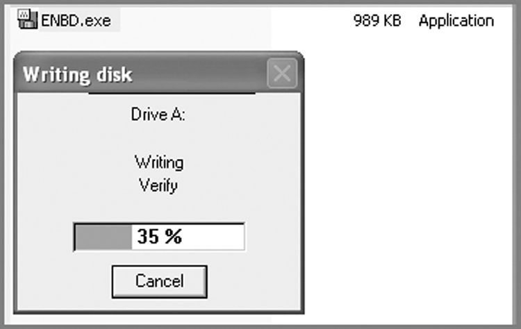
The ENBD.EXE file is a self-extracting floppy disk image, as shown in Figure 4-11. Since a floppy disk is a limited resource (1.44 MB), the amount of support you can pack on a floppy is limited. ENBD currently provides 29 different drivers supporting more than 190 device variants. The ENBD also comes in different flavors depending on the laptop PCMCIA NIC card it supports. These versions don’t have the variety of support, but they occupy less floppy disk space, allowing room for other tools. After extracting the ENBD to the floppy, you must also copy the version of EN.EXE that came with the version of EnCase you are running on the Windows machine. You can manually copy EN.EXE onto the floppy or use the EnCase Update Existing Boot Floppy feature.
Figure 4-11: ENBD self-extracting to a floppy; when done, place EN.EXE on the floppy before use.
Version Note
EnCase version 5 is the last version that comes with EnCase for DOS (EN.EXE). Using an EnCase boot floppy will not work with version 6 or 7. Various boot floppy images are still available on the Guidance Software website. The ENBCD, as described next, is also available on the website but won’t be updated for versions of EnCase newer than version 5.
Keep in mind, however, that a network cable preview and acquisition is available using Linux for EnCase (LinEn) in EnCase 6 and 7. I’ll discuss this tool later in the chapter.
Preparing an EnCase Network Boot CD
The ENBCD currently is a CD mirror of the ENBD in its full version. Because a CD provides much more file space, it ultimately has the potential to offer much more support than its floppy counterpart. The ENBCD is under constant development; the devices it supports are listed on the Guidance Software website. A major difference between the two is that the ENBCD already contains the most current version of EN.EXE. The caveat here is that problems can occur if the EN.EXE version does not match the version in use on the Windows platform. Therefore, make sure you use the correct version of the ENBCD. The extension of each ENBCD file indicates the EnCase version it contains.
The ENBCD is a self-extracting file that creates an ISO file and launches a quick set of instructions describing how to burn the CD image (ISO file) using either Nero or Roxio. You are given a choice as to where the ISO will be extracted. Take careful note of the location so you can find it again later. Easier yet, use the browse feature to move the ISO to your desktop. With Roxio, you need only to insert a blank CD and double-click the ISO image on your desktop, and everything happens automatically, making it a simple process and circumventing the steps provided in the instructions. Either way, creating the ENBCD is a simple process.
If your target machine contains a NIC that is supported by the ENBD or ENBCD, you are set to go. If your target machine does not have a supported NIC, you’ll need to install one in the target machine. You should choose one from the supported list of NIC cards and pack it, along with a spare, in your field kit.
The ideal configuration is to use a supported gigabit NIC in conjunction with a gigabit NIC in your examination machine. In that manner, you’ll get gigabit transfer speed between the two machines, and the network connection will not be the limiting factor. If both the DOS and the Windows platforms are robust systems, you’ll get extremely fast acquisitions.
Once you have a supported NIC in each machine connected via a crossover cable and you have created your EnCase network boot disk in either the floppy or CD version, you are ready to begin a network cable acquisition.
![]()
In lieu of ENBD/ENBCD, the machine containing the target drive can be booted with a forensically configured version of Linux. LinEn, which is EnCase for Linux, can be run in Linux in a manner akin to EnCase for DOS. A network crossover cable acquisition can be carried out in the same manner after LinEn is started. The Linux distribution will determine the level of support for NIC, SCSI, and USB devices.
Steps for Network Acquisition
When conducting a network cable acquisition, you should follow the steps discussed next.
Booting Up
The first part of the network acquisition process is safely booting up the target machine. Follow these steps:
1. With regard to the Windows machine, it is best to wait until the DOS machine is ready before starting EnCase in Windows. Simply run Windows with the crossover cable connected, don’t start EnCase, and focus your attention first on the target machine.
2. With regard to the target machine, as with the DOS drive-to-drive acquisition, you need to control and test the boot process so that the target machine boots from your ENBD/ENBCD before it attempts to boot from the target hard drive. The safest configuration is to enable a boot only from the floppy or CD and to disable the hard drive boot by removing the hard drive from the boot order altogether. Follow the procedures outlined in “Drive-to-Drive DOS Acquisition” earlier in this chapter to make certain the target hard drive is disconnected while you configure and test the boot order in the Setup utility.
3. Once you are completely satisfied that the boot process is tested and under control, reconnect the target media drive, make certain the network crossover cable is connected between the two machines, make sure the ENBD/ENBCD is in the boot drive, and reconnect the power cable. Boot the target machine (suspect or lab machine) with your hand on the power cord at the rear of the machine. If the machine doesn’t boot to the ENBD, disconnect the power at once.
4. Once the ENBD starts, a menu will appear with the following choices:
· Network Support: A second menu will launch providing various driver support installation options for network support. For network cable acquisitions, choose this option.
· USB - Acquisition (no drive letter assigned): If you want to acquire a USB device, this option loads the USB drivers to enable acquisition of a USB-connected device.
· USB - Destination (drive letter assigned): If you want to store an EnCase evidence file or other data to a USB-connected device, this option will load the drivers to allow you to mount a USB-connected device with a drive letter so that DOS can write to that drive. Since DOS is the operating system, it must be a FAT partition. After the ASPI USB Manager loads and configures your USB device, EnCase for DOS launches automatically. You have to look in EnCase for your drive letter. This is useful for drive-to-drive acquisitions when your storage drive is a USB-connected storage device.
· Clean Boot: As with a bare-bones floppy boot, you are presented with a DOS prompt from which you can carry out DOS tasks or launch EnCase for DOS (EN.EXE) without any of the ENBD supported features.
Setting Up Acquisition
The second part of the acquisition process involves loading drivers, setting up the access mode, choosing your connection type, and disabling firewalls:
1. You should choose #1, Network Support, to load network support options. You are next given a choice of several options. If SCSI devices are present, you should first load the SCSI drivers before the NIC drivers. The SCSI driver menu will offer an “autodetect” or manual select option. Autodetect usually works and is the recommended first choice. Once your SCSI drivers are loaded, if they were needed, you next load your NIC drivers. The recommended method is again the autodetect method. Manual selection and loading is usually necessary only if you encounter difficulty with the automated detection and installation methods. Once your NIC is detected and the DOS packet drivers are installed, ENBD launches EnCase for DOS preconfigured to run in the server mode. Note that the default mode is BIOS.
2. If you have chosen the ENBD because of HPA/DCO issues, you will have to press Esc and then click OK to temporarily shut down the server while you change the mode to Direct ATA access. Once that is done, press V or Tab to go to the Server to launch the Server panel. At this point, you have a choice to make between using a parallel port or a network connection. Choose Network, and you will be back where you were when EnCase started, with the program preconfigured to launch to this mode. At this point, EnCase for DOS is in the Server mode with a network connection listening for EnCase for Windows to connect. It is time to turn your attention to the Windows machine.
![]()
Note that one of your choices when starting the server (if you are using version 5 or earlier) is to use a parallel cable. Before network connectivity became available in EnCase, the parallel cable was the method of connecting two machines and pulling data from the target machine to the Windows examination machine. It still works, but it is horribly slow when you consider the size of modern hard drives. If no other options are available, this is still a choice. Instead of connecting the machines via network cable, connect them via a parallel cable. Instead of choosing Network on both the DOS and Windows machines, choose Parallel Cable. Aside from the speed difference, everything else is much the same. Parallel-cable acquisitions are not supported in EnCase version 6 and newer. If you think about it, it makes sense. Why support a feature that would take weeks or months to image today’s hard drive sizes?
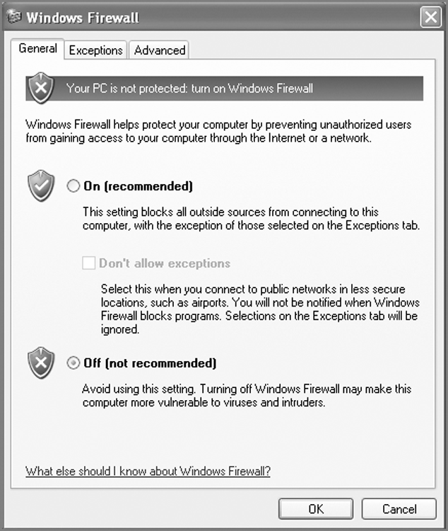
3. Before launching EnCase on the Windows machine, first consider firewall and other issues affecting connectivity. If you have your own firewall installed, you must configure it to allow EnCase to use a network connection. The numerous amount and types of firewalls prohibit a detailed explanation of how to do this. Suffice it to say that this approach won’t work until you configure your firewall to allow the EnCase network connection to pass. The easiest solution is to turn off your firewall altogether for this operation, remembering to enable it again when done. If you are using Windows XP Service Pack 2 or greater, a firewall is present. If it is present and enabled, it will prevent this connection until you disable it, as shown in Figure 4-12, or until you add ENCASE.EXE to the Exceptions tab. To access the Windows firewall options, choose Start > Control Panel > Windows Firewall. Alternatively, you can turn off the firewall altogether.
Figure 4-12: Windows XP Firewall options. Make sure Off is selected, or go to the Exceptions tab and add ENCASE.EXE as a program.
4. Usually you do not have to change anything on the Network Settings tab because EnCase usually works well and allows a connection without you altering anything. I recommend changing your network connections only if you have a problem. If you have difficulty achieving the network connection described in the next step, come back and adjust your network settings. Remember that when you are done, you’ll need to restore your previous settings if you want to connect to your network again! Therefore, note your settings before changing them. To modify your network settings, click Start > Control Panel > Network Connections. Next, right-click Local Area Connection, and choose Properties. Then, double-click TCP/IP, and the Properties dialog box will launch. Configure the settings as follows:
· Change to a fixed IP, entering 10.0.0.50 in the IP Address box.
· For a subnet mask, enter 255.255.255.0.
· Remove any DNS or WINS settings; they can prevent the crossover cable connection from taking place.
5. Once you are satisfied that a firewall won’t stop the connection, you are ready to launch EnCase in Windows. Open your case, or start a new case. (If you aren’t familiar with that process, refer to Chapter 6.) Click Add Device on the EnCase toolbar. In the resulting dialog box, place a blue check in the Network Crossover option in the right pane by simply clicking in the selection box. Click Next, and EnCase will poll the EnCase for DOS server for a list of the available devices. Select the device you want to examine, then click Next, and finally click Finish. EnCase for DOS will transmit the data to EnCase for Windows that allows you to view the file structure of the selected devices in the Windows version. This process may take a few minutes, depending on the network connection and the complexity of the device you selected. If you watch the EnCase for DOS server, the amount of data being transferred can be viewed in “real time.”
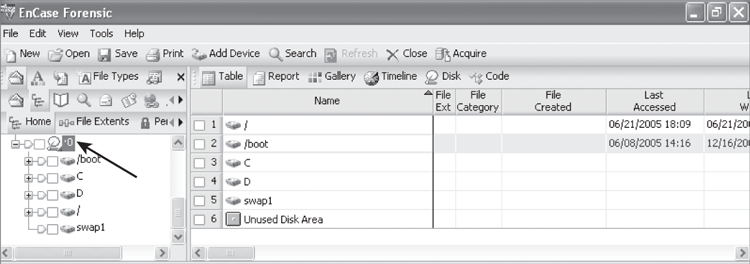
6. In this manner, you can now preview the selected device in EnCase for Windows, as shown in Figure 4-13. There is no local image of the remote drive; therefore, the data is pulled over the wire as it is needed for the preview. There can be a lag time when viewing large files. You can create bookmarks and a report of your previewed data at this stage. You can also create a logical evidence file to preserve individual files or entire directories on the target drive—before, during, or after the acquisition of the entire physical disk.
Figure 4-13: A drive being previewed over a network cable. Note the lower right of the physical device icon has a little blue triangle, indicating that the device being viewed is a live device vs. an image. You should note that this view involves EnCase 5.
7. If your intent was to preview only, you are effectively done and can disconnect after you have finished with the report of your findings. If, however, your intent is to acquire an image of the selected device, you can do so at this time. Go on to the next section.
Specifying Data Acquisition Options
Once you’ve connected your machines and are previewing the data on the target machine, you need to make several choices about how to capture, verify, and store the data. Follow these steps:
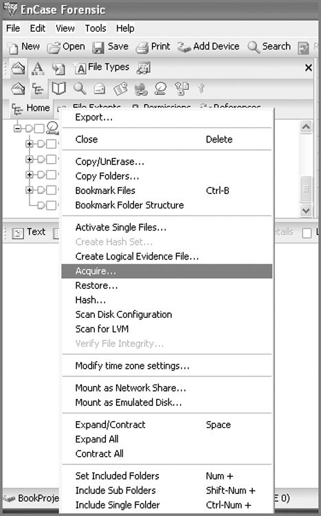
1. To acquire a device that you are previewing, in the left pane right-click the device you want to acquire, usually the physical device, so you can acquire all the data. From the resulting context menu, click Acquire, as shown in Figure 4-14.
Figure 4-14: To acquire a device being previewed, right-click the device, and click Acquire.
2. You are presented with a dialog box that basically tells EnCase what to do with the image after the image is acquired, as shown in Figure 4-15.
Figure 4-15: In this dialog box, you tell EnCase what to do with the image after it is acquired.
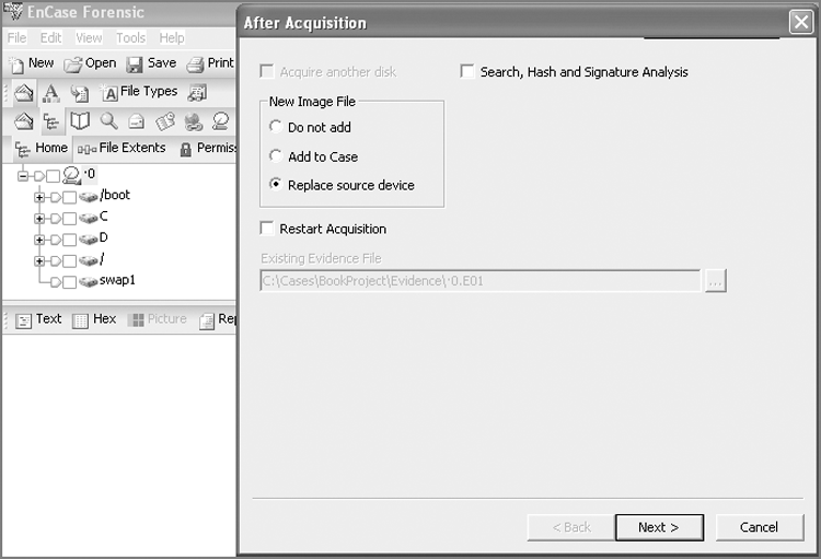
You can conduct a search, hash, and file signature analysis immediately following acquisition. If you are going to search, you must first have created and selected the keywords you intend to use. If you choose this option, you’ll have the ability to run any or all of these tools against either the entire case or the newly acquired device, with the latter being the default. If you are imaging a floppy, you’ll have the option to acquire another disk, and the next disk will sequence the number of the first disk by one to facilitate the imaging of a batch of floppies. With regard to the new image, you can choose whether to add it to the case. Another option is to replace the source drive that is already in the case with the image.
When the image is done, the image will replace the live device, and the little blue triangle will disappear. If you have previewed the drive, conducted searches, or made bookmarks, when the image replaces the source drive, those search hits and bookmarks will be resolved from the live device to the image.
A feature of EnCase 5 and newer versions is the ability to restart an acquisition in progress without starting over. For a host of reasons, an image can abort short of completion. With this option, you tell EnCase where the interrupted image file is located, and it picks up where it left off.
3. For the example’s purposes, you are imaging a hard drive over a network cable and want to replace the source drive with the image, so select the Replace Source Drive option. Because you have no search defined, leave that option unchecked. Since you aren’t restarting an image, you can leave that option deselected as well. At this point, you are ready for the next step. Click Next to see the wide range of acquisition options, as shown in Figure 4-16.
Figure 4-16: Acquisition options for EnCase 5 in Windows
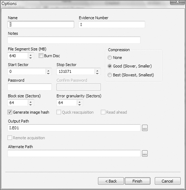
4. When you did your imaging in EnCase for DOS, you were presented with a linear series of questions and options. In EnCase for Windows, those options plus added features are all presented in one dialog box. When you type in the name of the evidence, EnCase automatically adds this name in the Evidence Number text box and appends the name to the path of the Output Path at the bottom of the dialog box. You can change either or both (Evidence Number or the filename in the Output Path text box) later if you want, but usually the default is the better option. You may want to double-check your output path to be certain it is going where you intend. Other options are as follows:
· Notes: As with EnCase for DOS, enter whatever brief notes you want that can help link the evidence to the case.
· File Segment Size: As with EnCase for DOS, this is the “chunk size” option that determines the size of the EnCase evidence files. They can range from 1 MB (to fit on a floppy) up to 2 GB. Again, the default of 640 MB fits nicely on a CD, and seven evidence files of this size fit on a 4.7 GB DVD. The default is the recommended setting.
· Compression: As with EnCase for DOS, you can choose to compress. Because compression takes less disk space but more time, you have to decide which is the scarcer resource when you have to acquire. EnCase for Windows gives you the added choice of a middle ground, where you can choose “good” compression instead of “best.” It’s a good compromise when both time and disk space are concerns. When doing a network acquisition, the compression occurs on the server side and can result in a faster acquisition if your network connection is slow or if you are using parallel cable because you have less data to pass through the connection.
· Start and Stop Sectors: As with EnCase for DOS, the defaults represent the beginning and end of the selected device. Recall from “Drive-to-Drive DOS Acquisition” earlier in this chapter that you may need to change this setting if you are acquiring a device that was restored onto a larger device. You would want to acquire only the sectors associated with the original device, not the extra sectors at the end of the larger device.
· Password: There is no difference between a password applied within EnCase for DOS or Windows, which means everything from the discussion about this topic in EnCase for DOS applies. Just remember, if you apply a password, don’t lose it!
· Block Size: This is a feature available in EnCase 5 and newer; it does not appear in EnCase for DOS. The block size refers to the size of the buffer used for acquiring data and computing the Cyclical Redundancy Check (CRC). DOS has an upper limit of 64 sectors, so this is not an option in DOS. With EnCase for Windows and LinEn, block sizes can range from 64 sectors to 32,768 sectors. I will discuss the EnCase evidence file in detail in Chapter 6, but for now you need to understand that EnCase normally writes a CRC for every 64 sectors of data. If you increase the block size, CRCs are written for larger blocks of data, thereby speeding up the acquisition process. If the block size is set to 256 sectors, for example, instead of writing a CRC for every 64 sectors, one will be written for every 256 sectors. You may be asking, why not make the setting 32,768 sectors every time and get the fastest possible acquisitions? As with many things in the computing world, performance gains often come with a trade-off. Every time that EnCase accesses data in the evidence file for processing, it first checks the integrity of that data by checking the CRC of the block in which the data resides. When accessing very small files, instead of checking the CRC of 64 sectors, EnCase must read and calculate the CRC of 32,768 sectors, which could slow down the program. Furthermore, if the evidence file contains a corrupted bit, EnCase knows only that the CRC for the block is bad and doesn’t know which bit is corrupted. The larger the block size, the larger the amount of data affected by this error. Although such problems are rare, they can and do occur. The default block size of 64 sectors is a good compromise that I recommend. If you increase it, just understand its impact in other areas. There is also a relationship between this setting and the setting that follows, Error Granularity.
· Error Granularity: This feature set was first offered with EnCase 5 and is available in EnCase for Windows, DOS, and Linux. In versions of EnCase earlier than version 5, if an error was found in one sector, the remaining sectors in that block were zeroed out to increase the speed of the acquisition, meaning data was lost. Numerically, this means a block of data contains 64 sectors, or 32,768 bytes. If only one sector (512 bytes) were bad, 32,256 bytes of good data would have been zeroed out when brought into the evidence file. Needless to say, 32,236 bytes of data could contain valuable evidence of guilt or innocence. The data is still available through a network preview of the drive with errors, but this is a time-consuming, manual process. The default setting for error granularity is 64, and if left unchanged, EnCase will handle errors as it always has, which is in the manner just described. You should leave this option set at 64 unless you encounter errors, because lowering it slows down the acquisition proportionately to the degree of granularity. If you encounter errors, you can acquire the image again with a lower Error Granularity setting. You can lower Error Granularity from 64 in powers of two, down to one (64, 32, 16, 8, 4, 2, 1). With a setting of 1, if one sector is bad, no good data will be zeroed out.
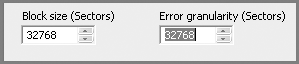
Thus far, I have discussed lowering the Error Granularity setting to capture more data if errors occur. Using a lower Error Granularity setting slows down the acquisition, and increasing the setting speeds up the acquisition. The upper limit for the Error Granularity setting is the block size. Figure 4-17 shows Block Size and Error Granularity settings of 32,768 sectors. With this setting, a CRC is computed and written for every 32,768 sectors instead of every 64 sectors. This setting also increases the buffer size (memory) to hold this data. Both combine to give faster acquisitions. However, these very large settings are not very practical, because one bad sector would result in the loss of more than 16 MB of good data. Again, the defaults of 64 are recommended. Note in EnCase 7 the options for granularity are Standard and Exhaustive. Standard is the same as the block size and Exhaustive is a granularity of 1 sector.
Figure 4-17: The Maximum Error Granularity setting is determined by the Block Size setting. Here they are both set at their maximum value of 32,768 sectors. Again, since we are using a legacy acquisition method, EnCase 5 is in use.
· Generate Image Hash: By default, this setting is enabled, and an MD5 hash value is computed for the device being acquired; that value is stored in the evidence file as a means of verifying the authenticity of the original evidence stored in the evidence file. An MD5 hash is a 128-bit value that is calculated based on an algorithm developed by Rivest, Shamir, and Adleman (RSA). It is often called an electronic fingerprintbecause it uniquely identifies any stream of data or file. The odds of any two files having the same MD5 are 1 in 2128, which is, more graphically, 1 in 340,282,366,920,938,000,000,000,000,000,000,000,000. Needless to say, when two files have matching MD5 values, there is an extremely high confidence factor in stating that the contents of the two files are identical. The MD5 algorithm, which is publicly available, is the industry standard in the computer forensics field. However, it does take time to calculate, so turning it off would speed up an acquisition. This might be of some value if you were testing or working on some data that was not of evidentiary value and time was critical. It is recommended that you always leave this feature enabled and that you generate an MD5 hash of all evidentiary data in accordance with best forensic practices.
· Quick Reacquisition: This feature was first offered in EnCase 5. It is an option only when you are acquiring an image from an EnCase evidence file. It is not available when acquiring a device. After you have acquired a device and created an image of it in the form of an evidence file, you may have occasion to acquire it again. The purpose behind doing so is to change certain limited properties of the evidence file. By reacquiring an evidence file, you can change its compression (adding or removing), you can add or remove a password, or you can change its file segment size (chunk size). Also, beginning with EnCase 5, you can adjust the block size or error granularity upon reacquisition.
Often you will acquire an image in the field without using any compression because that is the fastest way to acquire. You can also increase the Block Size and Error Granularity settings to further speed up the acquisition. When you get back in the lab and need to create your working copy of your evidence file, you can do so by reacquiring it with “best” compression. You may also change the Block Size and Error Granularity settings back to their defaults, increasing the integrity of the evidence file. You can then let the program run overnight, thus saving space on your lab drive, and store the uncompressed original separately when done. Reacquiring with or without compression does not in any way change the MD5 of the original data stream.
Adding or removing compression or changing the block size or error granularity requires a full reacquisition process and can’t be accomplished via the Quick Reacquisition option. The other two properties, changing a password or changing the file segment size, can be achieved quickly using the Quick Reacquisition option. Thus, if you need only to add or remove a password or change the chunk size, use this option to save time on the reacquisition process.
It is important to understand that reacquiring the image does not change the MD5 value of the original data stream acquired from the device if you change any or all of these five properties (compression, password, file segment size, block size, or error granularity).
The start and stop sectors can also be changed during reacquisition, but this is rarely done. If you acquire a physical device and want to reacquire only a logical partition, you can do so with this feature. You enter the start sector at the first sector of the partition and the stop sector at the last sector of that partition. Because you are changing the size of the original image, your new acquisition hash will be different from your original acquisition hash; they now represent different data streams. The new verification hash will match your new acquisition hash, however, during the verification process.
· Read Ahead: If you are using the Enterprise or FIM version of EnCase 5 or 6, this option speeds up acquisitions through sector caching. If you are not using Enterprise or FIM, this box is grayed out.
· Output Path: As previously mentioned, this value defaults to the proper location, and the filename is generated from the value you entered when you completed Name. If all is correct and to your liking, you don’t need to change it. If you want, simply browse to the desired location, also changing the filename if you prefer.
· Alternate Path: This feature is new to EnCase 6. If you are not sure your output path location will hold your intended image, you can specify an alternate path to hold the overflow. Although prior versions prompted you if you exceeded the capacity of your intended output, with the Alternate Path feature, it happens automatically without human intervention if you specify the alternate path.
5. When all acquisition options are set, click the Finish button, and EnCase will acquire the image according to the settings you entered.
The speed of your acquisition will vary depending on the size of your target drive, the speed of your network connections, the overall performance of your two machines, and the acquisition settings you specified. As EnCase acquires the data, it calculates the amount of data imaged as a function of the time required to do so. Based on the amount of data remaining to be imaged, EnCase gives you an approximation of the time required to complete the job. This data is displayed in the progress bar in the lower right. As the imaging progresses, the figure usually increasingly becomes more accurate.
If for any reason you need to stop the acquisition, you can do so by double-clicking the progress bar. A window will appear asking you whether you want to stop. Click OK, and the process will stop.
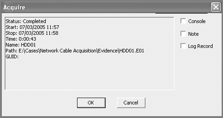
When the process has completed, an acquisition report window will appear that provides information about the acquisition. This information may be directed to the console for use by EnScript, to a note in your bookmarks, or to a log record, as depicted in Figure 4-18.
Figure 4-18: Acquisition completion report with options for directing the output to various locations
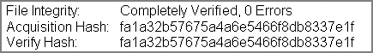
If you opted to have your image added to the case or to replace the source drive upon completion, a verification process starts immediately upon the image coming into the case. The verification process involves recalculating the CRC for each block in the data stream and recalculating the MD5 hash. All recalculations are compared with the original values, and all must match to successfully verify. The original hash value is called the Acquisition Hash, and the hash value calculated during verification is called the Verification Hash. To achieve a successful verification, all CRC acquisition values must match all CRC verification values, and the Acquisition Hash must match the Verification Hash.
Figure 4-19 shows the result of a successful verification where the verification process is reporting zero errors (all CRC values matched) and the Acquisition and Verification Hashes are showing identical MD5 values. The verification information is available on the Report tab for the selected device. Only when you have conducted a successful verification of your acquisition should you consider the job complete.
Figure 4-19: Verification shows zero errors (CRC values matched), and the Acquisition and Verification MD5 hashes are identical.
At this point, we’ll move away from legacy acquisition techniques and continue with our discussions of acquisitions using today’s software and hardware. You must, however, remember that there may come a time when you have to regress and use legacy methods if you encounter some type of legacy gear, because it is still out there. The more acquisition skills and capabilities you have, the better job you can do when facing atypical acquisition challenges.
![]()
Technology Time Warp
In a homicide case, in which there were three mistrials, the defendant attempted to introduce a falsified email into evidence between the last two trials. The attempt was detected, and a separate investigation was undertaken to investigate this additional crime. During the course of this investigation, we executed one search warrant and two attorney general’s subpoenas in the women’s correctional facility wherein the defendant was incarcerated.
Computer networks for computers used by inmates are nearly nonexistent. Rather, networking relies upon the “sneaker net,” which means placing data on floppies and moving data between computers in that fashion. And I did say floppies, not CDs and not USB devices. Most of the computers used by the inmates were donations, state surpluses, and the like. That said, legacy equipment was the norm, not the exception. And, media (floppies, and so on) are contraband and not to be kept in cell areas.
Few machines had CD drives, and USB ports were few and far between. Floppy diskette drives were present in every machine, and to say that the hardware and software was old was to understate the situation.
Since no Internet was present, no antivirus software was in use, and boot sector viruses were present on nearly every machine and floppy encountered. We imaged 30 computers and more than 150 floppies on three separate days. During the imaging of the 30 computers, we used a wide array of imaging techniques, including DOS boot floppies.
We rarely see today the boot sector viruses that permeated this environment. When taking the dd (Linux disk dump) images (the result of some of the imaging techniques used) back to the lab, they suddenly disappeared. Since they had boot sector viruses, the dd images were quickly picked off by the antivirus software on the lab machines and placed in quarantine. To get around this ongoing problem, all dd images had to be reacquired and placed in EnCase compressed images.
While such situations are uncommon, you never know when or where something like this could occur. Therefore, having legacy techniques available can save the day.
Accompanying me on this assignment was the lead homicide detective for the case, Detective Joseph Szczerba. As this very chapter was being written, on September 16, 2011, Joseph Szczerba was stabbed to death while subduing a violent offender. Lieutenant Szczerba was a cop’s cop, one of New Castle County’s best officers, and simply a great person. May his soul rest in peace.
FastBloc/Tableau Acquisitions
FastBloc was, initially, a hardware write-blocking device developed by Guidance Software to work in conjunction with EnCase, but it does not require EnCase. FastBloc write-blocking devices have been replaced by Tableau units. FastBloc or Tableau write blockers can function as a stand-alone write-blocking device in the Windows environment, allowing you to preview the data directly in the Windows Explorer interface. Additionally, you can run third-party tools such as antivirus or spyware detection software against the target drive with full write-block functionality. In fact, the hardware versions of FastBloc can be used on other operating systems.
With the release of EnCase 6 and continuing into EnCase 7, FastBloc comes in a software version as well, dubbed FastBloc SE (Software Edition). In fact, FastBloc SE was an added-cost option in EnCase 6, while, with EnCase 7, it is included as part of the basic software suite of tools. I cover this version in “FastBloc SE Acquisitions” later in the chapter.
Available FastBloc Models
FastBloc has truly undergone numerous model evolutions since its inception. All models provide write blocking for the target drive.
The original FastBloc is now called FastBloc Classic, which has a SCSI interface with the host computer. Although still supported, it is no longer available for purchase.
The second generation of FastBloc devices are the FastBloc LE (Lab Edition) and the FastBloc FE (Field Edition).
The FastBloc LE has an IDE interface with the host computer and is better suited for semipermanent installation on the host computer. With its IDE host interface, it can be used equally as well in a DOS or Windows environment.
The FastBloc FE was the first in the series to be designed for portability. It was designed for field use and has a flexible interface, allowing USB-2 or 1394a (FireWire) host interfaces. Although both interfaces are present, you are warned not use both at the same time!
The 1394a and 1394b protocols allow “daisy chaining” of FireWire devices, which means you can add one or more FireWire devices in a chain to the second FireWire FastBloc port, provided you have connected to the host computer via the other FireWire port rather than the USB port.
![]()
The daisy-chained devices attached to FastBloc are turned on or off with the FastBloc power switch. Furthermore, write blocking by FastBloc occurs only to the 40-pin and 44-pin IDE interfaces. Daisy-chained devices are not afforded write-block protection.
Any of the FastBloc devices mentioned thus far have an IDE interface that is write-blocked. With the addition of an IDE-to-SATA bridge, FastBloc can be used with SATA drives as well, greatly adding to its functionality.
FastBloc 2 Features
During 2006, FastBloc 2 was released. Like its predecessor, it was offered in field and lab editions, with the former being dubbed FastBloc2 FE and the latter FastBloc2 LE. The field edition, according to the Guidance Software website, contains the following features:
· Write-blocked, which protects the drive’s contents by preventing disk writes. Uses industry-proven WiebeTech write block firmware.
· Computer forensic software recognition, which is recognized and reported by EnCase software.
· Daisy-chained FireWire 800 ports for endless configuration capabilities.
· Individual OXUF922 bridge for perfect compatibility and fast performance.
· ATA-5 and ATA-6 compatibility. You can use your old drives and your new, big drives as well.
· Notebook drive capability with included 2.5-inch notebook drive adapter.
· SATA compatibility with included SATA adapter that expands the range of drives that can be attached and analyzed.
· Durable anodized aluminum construction, made with briefcase-tough aluminum.
· Self-aligning drive connector to easily attach and remove disk drives.
· LED status indicators that are power attached. On and access are discernible at a glance. Access LED is red for easy monitoring of drive activity. Other LEDs are green.
· 100-240 VAC power supply. It works anywhere.
· Plug and Play. No new drivers are necessary for using with Windows 2000, Windows XP, or Windows Vista; Mac OS 9.1, 9.2, or OS X; and Linux distributions that support FireWire.
· USB 2/USB support.
· Portable with Pelican carrying case.
This is clearly a major upgrade to the previous field edition version. Guidance Software partnered with WiebeTech to produce this version. Additionally, the FastBloc2 FE can be purchased with an adapter kit, which, per the Guidance Software website, contains the following:
· Adapter for Toshiba 1.8-inch drives (the type used in Apple iPods)
· Adapter for Hitachi 1.8-inch drives
· Adapter for microdrives (used in iPod Mini and in many digital cameras) or compact flash modules
· Adapter for PC Card drives, as used in PCMCIA slots
· 3.5-inch cable adapter (for accessing conventional IDE drives in hard-to-reach places in desktop computers)
· USB 2 cable
With the adapter kit, the FastBloc2 FE can be used to image the 1.8-inch drives found in iPods and some of the smaller laptops, as well as the new microdrives, making it much more versatile because it keeps pace with the new media being continually developed.
In 2010, Guidance Software acquired the assets of Tableau, LLC. In doing so, the FastBloc product line ended, and the Tableau product line took its place. Tableau manufactures a series of write-blocking forensic bridges in both field and lab or bay-mounted types, as shown in Figure 4-20. They work in much the same way as FastBloc products such that the directions and procedures for both products are quite similar. Even so, one should always review and follow the manufacturer’s instructions and resolve any differences using the manufacturer’s advice.
Figure 4-20: Tableau product line of write-blocking forensic bridges
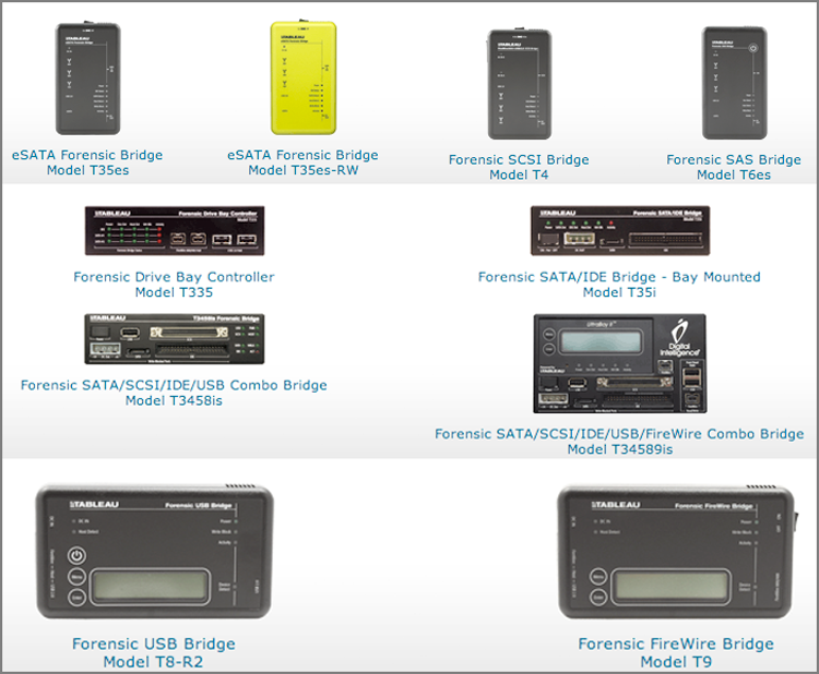
As for which models one should have on hand, much will depend on what devices you typically encounter; however, sooner or later, you can count on encountering most of the mainstream devices, meaning you need several models in your toolkit. The T35es model will handle IDE and SATA drives and will be the workhorse in your kit. USB thumb drives and external drives are ubiquitous, and the Forensic USB Bridge (T8-R2) is great for acquiring those devices. The FireWire Bridge (T9) is great for acquiring Macintosh computers in the Target Disk Mode (TDM) on the FireWire channel. If you work with high-end computer systems found in data centers, having a bridge for SCSI and SAS drives is needed for those times when you have to pull drives out of servers.
If you image mostly in labs, there is a series of bay-mounted forensic bridges. Which one you choose will largely depend on your needs and, of course, your budget.
No acquisition kit is complete without a series of drive adapters to connect the various connector types that seem to evolve overnight. These adapters will be needed for both IDE and SATA connections. Figure 4-21 shows the various types of adapters available from Tableau as of press time.
Figure 4-21: IDE and SATA disk adapters available from Tableau
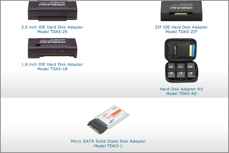
Steps for Tableau (FastBloc) Acquisition
To conduct a FastBloc acquisition, you should follow these steps:
1. Connect your FastBloc to your host computer via either a USB or a 1394a/b connection (both are available on FastBloc2 FE), but not both. The host computer can be running when you make this connection, or you can make your connections while the computer is off and then boot the system.
2. Your target drive should be set for master or single if it is a Parallel ATA (PATA). Adjust the jumper accordingly. Western Digital drives can be a little persnickety and often work better with no pins at all. If your drive does not require configuration as to master/single and so forth, then disregard this step.
3. Connect the DC power from the FastBloc to the target hard drive. This applies only to 3.5-inch drives; 2.5-inch drives from laptops derive their power (5 volts only) directly through their 44-pin connection or through other connections for even smaller drives (1.8 inch drives, microdrives, and so forth).
4. Connect the IDE cable from FastBloc to the target hard drive. Most 3.5-inch hard drives should be connected using the 80-conductor cable. Some older drives, designed to operate with the 40-conductor cable specification, should use that cable. Laptop drives should be connected to the 44-pin connection. When connecting IDE connections, take care to attach the pin-1 connection to its corresponding pin-1 connection on the cable. If you are connecting the newer microdrives in their various sizes and flavors, you’ll need to use an adapter that is provided with the FastBloc2 FE adapter kit to connect the target drive to FastBloc2 FE.
![]()
Most connectors are “keyed” with a notch to prevent incorrect connections. Believe it or not, with a little force you can bypass this protection, thus forcing the protruding notch to fit where it isn’t supposed to fit, totally reversing all of the connections. The sidewall of the connection flexes and bulges outward to facilitate the notch. When IDE connectors get “worn,” this is even more likely to occur. Just because it “fits” doesn’t make it right! Pay careful attention to what you are doing, or you may see smoke where it shouldn’t be. Also, take care if using longer IDE cables; the closer you get to the 18-inch maximum, the more likely communications errors will occur.
![]()
Flat-ribbon cables don’t like being bent and twisted, especially repeatedly. They protest this treatment by failing when you least want them to fail! Invest in a few 6-inch and 12-inch-round shielded IDE cables with a single IDE 40-pin connection on each end. Use the 6-inch one when you have the hard drive detached, and use the 12-inch one when you have to “reach” a mounted hard drive in a case. The shielding in these cables guards against communications errors, facilitating fast, error-free acquisitions. The round cable design makes them flexible and impervious to wear and tear from the repeated use that is typical of forensics work.
5. Connect the power supply to FastBloc, and power on FastBloc. If the host computer is already running, Plug and Play (PnP) should recognize FastBloc and mount the attached hard drive.
6. If the host computer is not on, boot it up at this time. During start-up, PnP should recognize FastBloc and mount the attached drive.
7. You can confirm that FastBloc (or Tableau) was detected and mounted by opening the Device Manager (right-click My Computer, and choose Properties; on the Hardware tab, choose Device Manager). Under Disk Drives, you should see FastBloc listed, as shown in Figure 4-22. If Windows can recognize and successfully mount any of the partitions on the target drive, it will do so when FastBloc is mounted. When this is the case, you can preview the partitions with Windows Explorer. Sometimes partitions aren’t mounted, but they are partitions that Windows should recognize and mount. Perhaps there is something about the partition that Windows finds problematic and won’t mount. If the physical drive is mounted, EnCase will see the partitions when Windows refuses to do so.
Figure 4-22: When FastBloc is successfully detected and mounted by Windows PnP, FastBloc is listed under Disk Drives, as shown here in the Windows Device Manager.
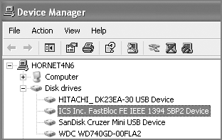
8. Run EnCase in Windows on the host examination computer to which FastBloc is attached. Open a case, or start a new case. When a case (new or old) is open, you’ll be on the case home page. Under the Evidence section, click Add Evidence.
9. On the screen that follows, since FastBloc mounts the drive locally, choose Add Local Device, as shown in Figure 4-23.
Figure 4-23: FastBloc is a mounted local device; therefore, you can click Add Local Device to access FastBloc.
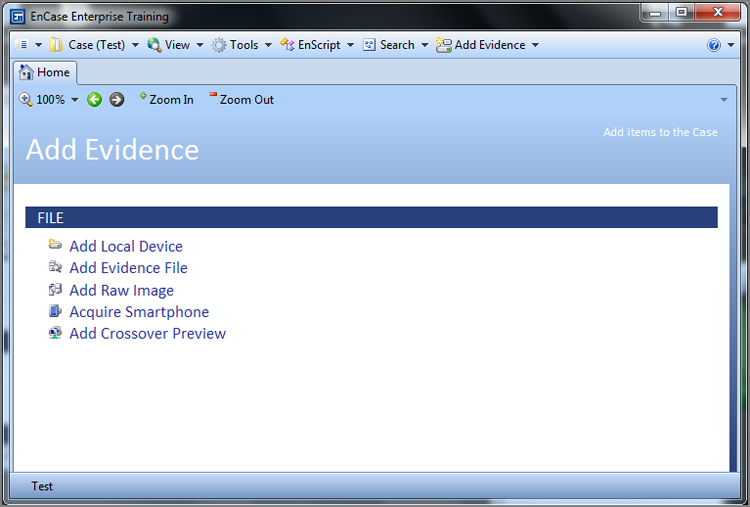
10. On the screen that follows, accept the defaults for now, unless you are using a legacy FastBloc, meaning one predating the Tableau units. If you are using a legacy FastBloc, check the box Detect Legacy FastBloc, as shown in Figure 4-24, and click Next. The Add Local Device screen appears next as a listing of all local devices (physical and logical), as shown in Figure 4-25. EnCase 7 shows volumes under and offset from their parent physical devices, making them much better to comprehend at a glance. Under Choose Devices, you see a listing of all local devices, both logical and physical. Recall that the blue triangle at the lower-right corner of the icon denotes a live device. FastBloc doesn’t have a blue triangle; instead, it has its own special icon, making it easy to identify the write-blocked target drive. The FastBloc icon is the device symbol with a square around it in (blue in EnCase 5 or green in EnCase 6 and 7). Additionally, in the Write Blocked column, you’ll see an indicator in the column next to the FastBloc device. The indicator is a Boolean indicator for true, meaning the device is write-blocked. Sometimes this blue square or green square can be missing along with the Boolean indicator for true in the Write Blocked column. The cause is typically a cable issue or an improperly jumpered drive. Even if the blue or green square and the Boolean indicator for true are missing, the device attached to FastBloc is still write-protected. With a blue check, select the physical device that is indicated with the FastBloc icon, as shown in Figure 4-25. Any mounted partitions on the device connected to FastBloc will also be displayed with a green square. Selecting the physical device gives you all the sectors on the physical device, whereas selecting the logical device gives you only the sectors within that partition. Almost always you will seek all the sectors and will select the physical device.
Figure 4-24: If using a legacy FastBloc (predating Tableau units), you must check this box for detection to occur.
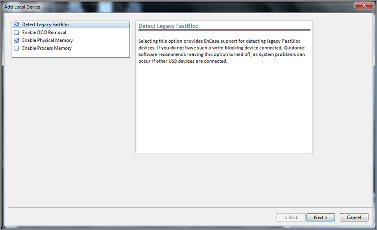
![]()
The Boolean indicator for Show True is, by default, a dot. For Show False, the default indicator is nothing or null. Many examiners prefer to change this to Yes and No for added clarity. You can do this by choosing Tools > Options > Global. You can replace the dot for Show True with Yes and the null for Show False with No. Figure 4-25 reflects this change.
Figure 4-25: Choose Devices window. FastBloc devices are denoted with a blue square (EnCase 5) or a green square (EnCase 6 and 7) icon indicating their write-blocked status.
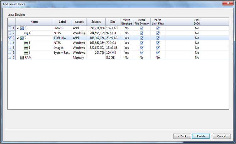
11. Before clicking Next to proceed, confirm that EnCase, through the BIOS interface in Windows, is able to see all the sectors on the drive as reported by the manufacturer. For the FastBloc physical device (not logical!), check to see that in the number of sectors reported by EnCase in the Sectors column (in this case 488,397,168) matches the number reported by the manufacturer for this drive on its website. Also, note that there is a column named Has DCO. If present, a Yes will appear. If a DCO is present, return to the previous screen, check Enable DCO Removal, and then proceed. Once satisfied, you can access all the sectors on your target drive, select the FastBloc physical device, and click Finish.
12. Upon clicking Finish, you’ll see your evidence object appear as a row on the Evidence tab, which is immediately to the right of the Home tab, as shown in Figure 4-26.
13. To preview your evidence object or drive, you should place a blue check on it and click Load Selected Device on the Evidence Tab toolbar, or you can simply double-click the object. It will take a few minutes for the device to be parsed and viewable in the Tree pane, which will appear in a few minutes. Most veteran users of EnCase will recognize this view when it loads. Figure 4-27 shows the Tree pane.
Figure 4-26: Evidence object appearing as a row on the Evidence tab
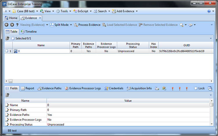
Figure 4-27: EnCase 7 Tree pane from which you can navigate the device. From this pane, you can also acquire the live device being previewed by placing the object to be acquired in the Table pane, selecting it, and clicking Acquire on the Evidence Tab toolbar.
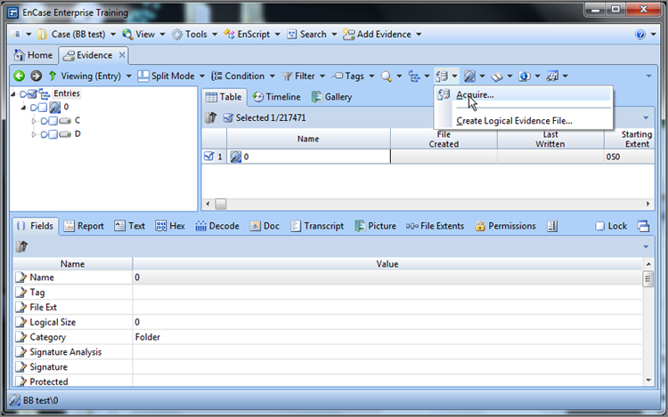
14. At this stage you can preview the drive, searching and bookmarking as is necessary. In Exercise 4.1, you will have the opportunity to preview your own hard drive, and you’ll see how this works. You can also produce a report and print it directly or save it as a web document or as a Rich Text File (RTF)-formatted file, which is usable by most word processing software. If you create search hits, bookmarks, and so forth, and acquire the device (selecting the Replace Source Drive option), those search hits and bookmarks will transfer and resolve to the image, keeping your work intact.
15. If you opt to acquire the FastBloc/Tableau device, you can do so at this time. The acquisition will occur completely in the EnCase for Windows environment with full hardware write-block protection for the target drive. Veteran EnCase users are used to right-clicking and the device and choosing acquire, but EnCase 7 no longer provides that option. Acquisition is available by many means. If you chose to process the evidence object on the Evidence tab’s Table pane, you could acquire it as a precursor to processing for evidence. From the Tree pane, where you currently are, you can also acquire. First, from the Tree pane, force the object to be acquired to appear in the Table pane. Place your cursor on that object in the Table pane. With the focus on the object to be acquired, click the Acquire icon on the Evidence tab’s toolbar, which is shown in Figure 4-24. At the far right of the same toolbar is a drop-down menu from which acquisition is also available.
At this point, you will see the EnCase 7 acquisition options. Previous versions have placed this information on one busy menu screen, whereas EnCase 7 spreads them out over three tabs, which are Location, Format, and Advanced.
Figure 4-28 shows the Location tab where the name, evidence number, and notes are entered. In addition, the Mirror Acquisition, Restart Acquisition, and Remote Acquisition options are available. Finally, the output path can be selected as well as an alternate path in the event the primary path is insufficient to contain the data.
Figure 4-28: EnCase 7 acquisition options Location tab
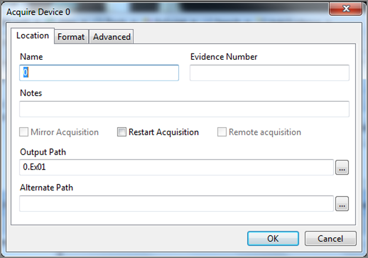
Figure 4-29 shows the Format tab where the evidence file format (Ex01 or E01) can be selected, as well as compression, hashing, and file segment size options. From this tab you can also apply encryption to the evidence file and set a password, although this is not normally recommended.
Figure 4-29: EnCase 7 Format options tab
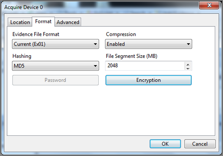
Figure 4-30 shows the Advanced tab where the Block Size, Error Granularity, Start Sector, Stop Sector, Read Ahead, and thread options can be set.
Figure 4-30: EnCase 7 Advanced options tab
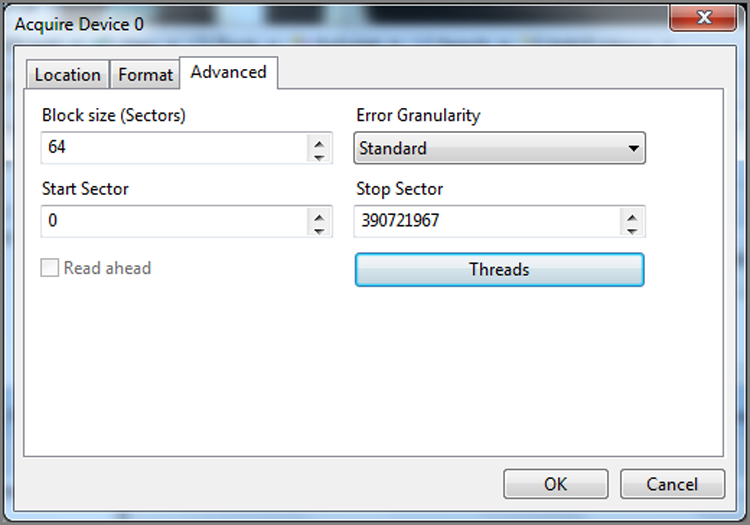
When your acquisition is done, on the Report tab for the imaged FastBloc device, a notation appears that the acquisition was completed using FastBloc, which documents the write-protected acquisition method.
![]()
Although you can use other hardware write-blocking devices in EnCase, only FastBloc or Tableau units will currently show with a blue square icon (Version 5) or a green square icon (Version 6 and 7) and the Boolean true for write-blocked. Also, only FastBloc or Tableau will show as write-protected in the device-acquisition report.
![]()
Windows 7 is currently recommended for running EnCase 7. The 64-bit version is much preferred over the 32-bit version because EnCase needs the resources and memory management provided by this platform.
Exercise 4.1
Previewing Your Own Hard Drive
Previewing your own hard drive using EnCase is an excellent technique for testing and research. You can also use it to study or familiarize yourself with various acquisition options.
You may also find it helpful to refer to Figures 4.22 through 4.30 if you need help or visual support.
1. Launch EnCase (with dongle), start a new case, and simply accept the defaults.
2. Click Add Evidence.
3. Click Add Local Device, accept the defaults on the screen that follows, and click Next.
4. Place a blue check next to your hard drive (the physical device; your boot or system hard drive will usually be drive 0), and click Next. Then click Finish on the next screen. EnCase should return you to the Evidence tab with your hard drive showing as an object in the Table pane.
5. To have EnCase parse your drive and show its objects, you must blue check (select) the drive and select Load Selected Evidence from the Evidence tab’s toolbar or simply double-click the drive. It will take a few minutes to parse and load.
6. Once EnCase has parsed your drive, it will appear in the Tree pane. You can preview it at this point if you’d like.
7. In the Tree pane, place your cursor on Entries, at the top or root level. This will force your hard drive, the physical device, to appear in the Table pane. In the Table pane, place your cursor on this physical device. By placing your cursor (focus) on it, it becomes the object or your next action, which is acquisition. With your focus on your drive, click the acquisition icon and drop-down menu on the Evidence tab’s toolbar (refer to Figure 4-24 for help locating this icon). From this drop-down menu, choose Acquire.
8. From the Location tab, under Name, type a name, such as HDD01. Note how EnCase automatically inserts this name in one other location, which is in the filename portion of the Output Path entry. You can change this if you’d like.
9. From the Format tab, note that the default evidence file format is ex01, that compression is enabled by default, that the MD5 hash is the default, that the file segment size is 2048 MB (2 GB), and that no password / encryption is enabled. I suggest looking at the options for each of these settings.
10. From the Advanced tab, note that Block Size is set to 64 sectors. Note that Error Granularity, by default, is standard. With EnCase 7, Error Granularity is no longer an integer but rather either Standard (same number of sectors as the block size) or Exhaustive (one sector). Unless you have a reason to do otherwise, these default settings are recommended. Next, you can see your Start and Stop Sector defining the range of your acquisition. Normally you would not need to change these. Finally, you see that you can adjust the threads, both reader and worker threads.
11. Click Cancel, and you are back to your case.
12. From the Tree pane, click the back or left arrow (situated directly below the Home icon) to return to the Table pane of the Evidence tab. Place a blue check on your hard drive. On the Evidence tab’s toolbar, click Remove Selected Evidence.
13. Close EnCase.
FastBloc SE Acquisitions
Beginning with EnCase 7, FastBloc SE is part of the basic feature set and is no longer an added-cost option.
About FastBloc SE
With this version of FastBloc, SE, you can use special drive controller software in EnCase to control reads and writes to attached evidentiary media. FastBloc SE can control writes to Plug and Play drives on USB, FireWire, and SCSI channels.
HPA and DCO
Earlier in this chapter, I discussed HPA and DCO, which are special protected areas of a hard drive that are ordinarily hidden from view. As you’ll recall, to view them in EnCase for DOS, you had to use the direct access mode.
With FastBloc SE, HPA and DCO support is present as long as the controller card in the forensics machine is ATA-6 compliant. If only an HPA is present, the HPA settings are temporarily removed and later replaced. If a DCO is present, the DCO settings are permanently removed. If a DCO and an HPA are present, both the HPA and DCO settings are permanently removed.
These settings are stored in the onboard controller memory only. No changes are made to the data stored on the drive. Nevertheless, you should document this change when you encounter it.
Steps for FastBloc SE Acquisitions
To use the FastBloc SE to protect Plug and Play USB, FireWire, or SCSI devices from writes, first make sure no devices are attached. Once that is done, follow these steps:
1. Launch EnCase, and choose Tools > FastBloc SE, as shown in Figure 4-31.
2. From the ensuing dialog box, choose Write Blocked, as shown in Figure 4-32. At this point, the EnCase software begins scanning the buses, watching for any device to be attached. When one is detected, EnCase imposes a write block on it and notifies you.
Test First!
Before acquiring real evidence, you should, according to best practices, test the hardware and software to make certain that write-blocking protection is being successfully implemented. To do so, mount a nonevidentiary drive, one that has been hashed first, in the write-protected configuration described previously. Although the drive is write-protected, you should attempt to alter data on the drive. When done, shut down the forensic computer, remove the test drive, and hash it again on a known platform or device. Both hashes should match, and if they don’t, you have a problem with either hardware, software, or technique. You should repeat your test a few times and document the results. If at any point either the hardware or software changes, you should test and document again.
Figure 4-31: The FastBloc SE option on Tools menu
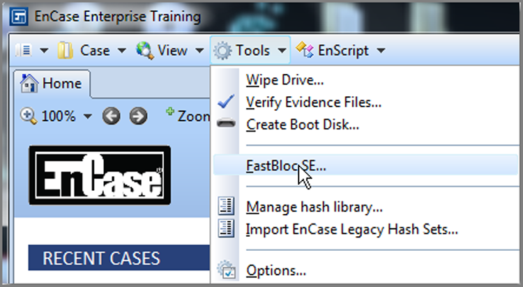
Figure 4-32: The FastBloc SE dialog box
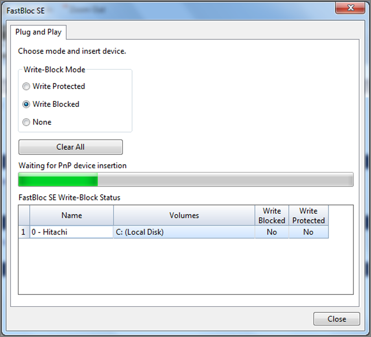
3. Attach the PnP device to the system (USB, FireWire, or SCSI).
When the device appears in the list of volumes and you see Yes or a dot in the Write Blocked column, as shown in Figure 4-33, the attached device is write-blocked.
Figure 4-33: The FastBloc SE dialog box showing the device attached and its “write-blocked” status
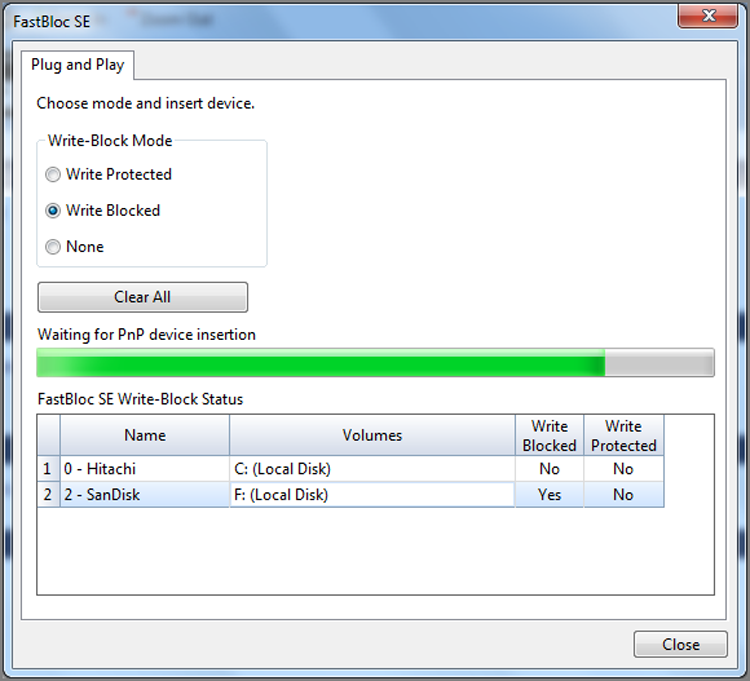
4. In EnCase, either create a new case or open an existing one.
5. On the case home page, click Add Evidence and then Add Local Device. On the page that follows, accept the defaults and click Next. On the screen that follows, shown in Figure 4-34, you will see a dot or Yes in the Write Blocked column, and the icon for the device will have a green box around it, both indicating a successful write block.
Figure 4-34: List of local devices showing that the device just added is write-blocked
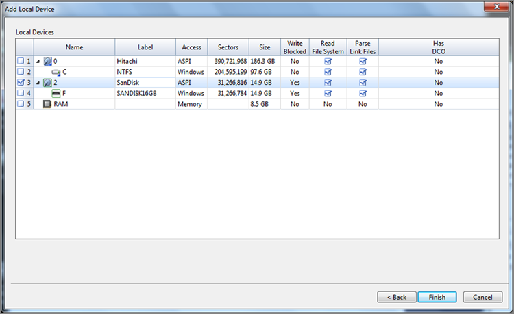
6. Select the write-blocked target device (blue check), and click Finish. The device will appear in EnCase in the Evidence tab’s Table view. At this point, you can choose to process and acquire as part of the processing. Alternatively, you can double-click the evidence object, causing it to parse and be displayed in the Tree pane. From the Tree pane, you can preview and acquire in the customary manner.
Write Block or Write Protect?
With the FastBloc SE tool, you have the option of two different types of write blocking or protecting. For sure, both protect the device from writes. If you choose Write Block, writes are prevented but are cached locally to prevent Windows error messages. If you choose Write Protect, writes are prevented, nothing is cached locally, and Windows launches error messages when writes are attempted, which occurs upon mounting. Unless you enjoy Microsoft error messages, you will usually use the Write Block option. Some users, however, enjoy the reassurance of the error messages, because they know that write protection is at work.
When you are finished previewing/acquiring the write-blocked device, carry out the following steps to remove the device and the write-blocking feature:
1. Physically remove the device from host computer. You could attempt to eject it, but the system will see the device in use and not allow it to be stopped. Because it is write-blocked, physically removing it will not harm it.
2. Next, you need to stop the write-blocking software in EnCase. In EnCase, choose Tools > FastBloc SE. Refer to Figure 4-33, and note that there is a Clear All button. Click this button, and you’ll receive a Clear All confirmation window (Figure 4-35) asking whether you want to remove the write-blocking protection. Choose Yes, and you’ll receive confirmation that it has been done and will take effect when the next device is plugged in, as shown in Figure 4-36. Next, close the FastBloc SE dialog box, and you are finished.
Figure 4-35: Confirm the All Clear window that removes write-blocking on all devices.
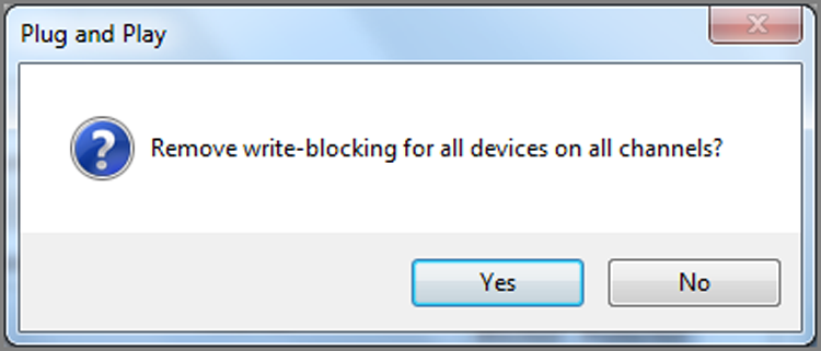
Figure 4-36: Confirmation that write blocking has been removed
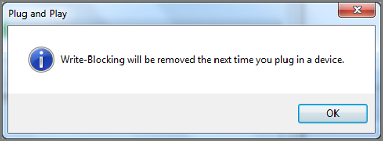
FastBloc SE is a powerful and versatile set of various write-blocking utilities. The USB, FireWire, and SCSI write-blocking tools don’t require any hardware, relying upon write blocking at the Plug and Play level, and make them quite handy for field work. Either way, examiners are given more options and tools to protect evidentiary media in a world of rapidly evolving media types.
LinEn Acquisitions
LinEn, or EnCase for Linux, is a new feature of EnCase 5 and newer versions. Since EnCase 6, the DOS version of EnCase (EN.EXE) is no longer provided, and you will have only LinEn available. LinEn is similar to EnCase for DOS, but it offers all the advantages of running under Linux. DOS is a legacy 16-bit operating system, whereas Linux, like Windows, is a 32-bit or 64-bit operating system. Thus, you get tremendous performance advantages using LinEn compared to EnCase for DOS.
Mounting a File System as Read-Only
Unlike DOS or Windows, Linux enables you to manually select whether you want to mount a file system as read-only. In doing so, you are able to manually mount target evidence media in a write-protected manner, protected by the operating system instead of other methods or devices. To achieve this, however, you’ll need to turn off the automounting of file systems in Linux so that when it boots, file systems are not mounted. That enables you to mount devices manually, carefully controlling the process. To do this in SUSE and Red Hat, do the following:
· For SUSE, run Yast (Yet Another System Tool) by choosing Main Menu > System > Configuration. Open the Runlevel Editor, and disable the autofs feature.
· For Red Hat, run Services, which is located in Main Menu > System Settings > Server Settings. Disable the autofs feature.
Many people prefer to run LinEn from their favorite Linux distribution on a boot CD, such as Helix, Knoppix, SPADA, and so forth. Many of these security distributions of Linux already boot with the automounting of file systems disabled or mount systems read-only, depending on how they have been configured or reconfigured in some cases. You should test your version to see how it mounts file systems when it boots. You could remaster the boot CD to include LinEn, but that necessitates doing so each time LinEn is updated. Instead, place your updated copy of LinEn on your FAT32 storage volume or removable USB drive, and run LinEn from that location. This keeps your Linux boot CD clean with no need for constant updating and places the updated copy of LinEn on the writable storage volume, making for an efficient working platform or methodology.
LinEn Ships on Helix and Other Linux Security Boot Disks
Various versions of Helix (available from www.e-fense.com/helix/) actually include LinEn in their GUI under Forensics, making it easy to use. The latest version of Raptor now includes LinEn as well.
EnCase can update the Helix distribution with the latest version of LinEn. This does not replace the version of LinEn that ships with Helix. Rather, EnCase places the updated version in the root of the CD. If you run LinEn from the Helix GUI, you’ll run the older version. To run the updated version, use the root console, making sure you are root (# in the prompt). At the command line, type the following, pressing Enter after each line:
cd /cdrom
./LinEn
The LinEn console will run, and you can acquire using the newest version of LinEn. Before you do this, however, you’ll need to mount a read-write drive on which to place your image, or you’ll need to prepare your network connections if you plan to do a network connection to make your acquisition. The instructions for these tasks follow. For now, I just wanted you to know about Helix and how to access the updated version of LinEn that EnCase can install onto Helix.
This version of Helix (free version) is no longer available as a free download. Paid users of Helix 3 have access to the last free version from the download area at www.e-fense.com. Because this distribution was widely used and circulated, it is very much still in use and popular, although its use will certainly begin to fade as the outdated Linux kernel starts to get long in the tooth and fails to support newer hardware. Meanwhile, for those still using it, the previous information very much still applies.
Updating a Linux Boot CD with the Latest Version of LinEn
To update a Linux boot CD, you’ll first need to render the Linux boot CD into an ISO image. There are many tools to do this. I like to use WinISO for this purpose. Once this step is done, follow these steps:
1. Launch EnCase, and choose Tools > Create Boot Disk. You’ll see the dialog box shown in Figure 4-37.
2. Choose ISO Image, and click OK. You’ll see the Formatting Options dialog box, as shown in Figure 4-38.
Figure 4-37: The Choose Destination dialog box
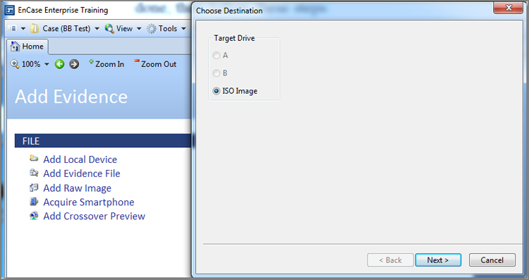
Figure 4-38: The Formatting Options dialog box
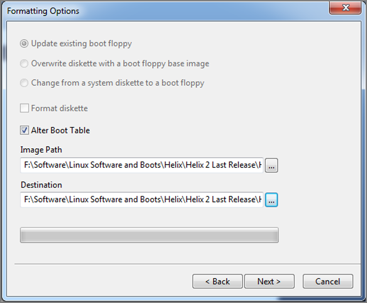
3. Choose Alter Boot Table check box, browse to the path containing the ISO file, and then browse to a path and filename for your modified ISO that EnCase will create. When ready, click Next. The next dialog box, shown in Figure 4-39, allows you to add files to the ISO image.
Figure 4-39: The Copy Files dialog box
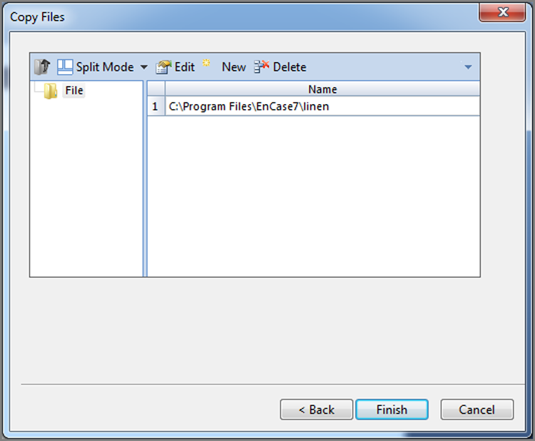
4. In the Copy Files dialog box, right-click in the right pane, and choose New. You will then be able to browse to the location of LinEn, which is in the root of the folder Program Files\EnCase7. When ready, click Finish, and EnCase will insert the updated version of LinEn in the root of the CD and will create the new ISO at that path you specified.
5. Your final step is to burn the ISO onto a CD using the burner of your choosing.
Running LinEn
When running LinEn, you must be running as root because you must be in total control of the system. Although LinEn will run in the Linux GUI, the GUI uses system resources and limits the resources available to LinEn. For best performance, run LinEn in the console mode.
![]()
The next paragraph contains instructions for those running Linux from a hard drive installation. Changing the runlevel on a CD distribution is for advanced Linux users.
To configure Linux to boot in the console mode, you’ll need to modify the boot runlevel, which is controlled by the file inittab located in the /etc folder. Edit the inittab file with your favorite text editor (vi is one such tool). Locate the line in the inittab file that reads id:5:initdefault:. The 5 tells Linux to boot to the GUI. Change the 5 to a 3, which will cause Linux to boot to the console mode. Remember to save your changes! When Linux reboots, it will start in console mode. You should leave your forensic Linux system set up to boot this way. You can always run the GUI by typing startx.
Before mounting drives and starting LinEn, you need to get used to a different way of looking at devices from what you might be accustomed to viewing in Windows. Linux will list IDE devices as follows:
hda: Primary Master
hdb: Primary Slave
hdc: Secondary Master
hdd: Secondary Slave
For partitions on a hard drive, Linux will append a partition number to the hard drive designator. Examples include the following:
hdc1: Secondary Master First Partition
hda3: Primary Master Third Partition
If you are not sure what devices are on a system, at the console type fdisk -l, and the devices will display. If you want to see all the mounted devices, type mount at the console, and press Enter. All mounted devices and their properties will display. To see more display options for either of these or any Linux command, type man fdisk at the console, and press Enter. Replace fdisk with the command of your choice to see others. The command man stands for “manual,” and you are asking to read the manual for any command that follows man.
Before you start, have a storage volume ready to accept your EnCase evidence file. When creating any storage volume, it is recommended you employ best forensic practices and wipe the drive first. This avoids any claims of cross-contamination of evidence file data. Use a FAT32 volume with a unique volume label for this purpose. Although Linux can read NTFS, with the appropriate distribution or module, writes to NTFS are not stable enough for evidentiary work, with few drivers available for this purpose (and they are in beta at best). An EXT2/3-formatted partition can be used for faster evidence file writing in Linux; however, the evidence file segments must be moved to a FAT or NTFS partition prior to examination with EnCase Windows. Optionally, you could load a driver to allow Windows to mount EXT2/3 partitions, thereby allowing direct use of the EXT2/3 partitions. Given that, you should connect your storage volume to your Linux imaging platform.
Linux Writes to NTFS
Currently, most Linux distributions ship with the relatively new NTFS-3G driver, by which Linux can both read and write to NTFS partitions. In the event you are using an older distribution, you can download the driver. As with any change, you should test and validate before using it in a forensic setting.
At this point, you should be ready to begin. You should have done the following:
· Configured your Linux system so that the autofs (automounting of file systems) is off and file systems will not be mounted on boot.
· Configured your Linux system to boot into the console mode.
· Attached your target drive to the Linux imaging platform.
· Attached your storage drive (FAT32 with unique volume label) to the Linux imaging platform.
· Placed LinEn on either the Linux volume or the storage drive. Either way, it should be in a known location so you can easily find and execute it.
Steps for LinEn Acquisition
To conduct an acquisition using LinEn, you should follow these steps:
1. Boot your Linux machine to the console, and log in as root.
2. Check to see what file systems are mounted. Type mount, and press Enter. Your target drive should not be mounted.
3. Check to see what devices are available. Type fdisk -l, and press Enter. Locate your target drive and your storage drive. You should know how you connected them (primary master, and so on) and should be able to locate them using the Linux naming convention (hda for primary master, and so on).
4. Mount your storage drive. Create a directory by typing mkdir /mnt/fat32. Mount the storage volume on this mount point by typing mount /dev/hda1 /mnt/fat32. Remember that Linux is case sensitive and that FAT and fat are quite different in Linux. Remember also that hda1 means the first partition on the primary master. If you storage volume is elsewhere, adjust accordingly.
5. Check that your storage drive is mounted by again typing mount and pressing Enter. You should see your storage volume mounted.
6. If you have not yet done so, create the folder on your storage volume to hold the EnCase evidence file. (This location must already exist and will not be created by LinEn.) Do so by typing cd /mnt/fat32. You will be in the root of your mounted storage volume. Using the mkdir command, you can create a suitable directory, such as /cases/casename/evidence. It is best to do this when you format it and when you don’t have evidence drives mounted. With that methodology, mistakes are less likely to occur.
7. Navigate to the location where LinEn is located. Assuming it is in /mnt/fat32/encase/LinEn, type cd /mnt/fat32/encase, and press Enter. Then type ls -al, and press Enter. You should see LinEn, but note that the default name is all lowercase, linen. Because Linux is case sensitive, you must type it as it appears! If you prefer it as LinEn, as it is often dubbed, just rename it.
8. Launch LinEn by typing ./LinEn and pressing Enter. Unless the path where LinEn is located appears in your defined PATH, you’ll need to prefix the command with ./, which tells Linux to look in the current directory for the command that follows. There is no space between ./ and the command that follows, LinEn. If you insert a space, you’ll get an error. If you get a Permission Denied error, you’ll need to change the permissions on the file. Type chmod 777 LinEn, and it should work.
9. LinEn should launch, and you should see an interface that is similar to EnCase for DOS. Note that the Lock tab is missing; Linux is handling that function. Linux communicates directly with the hardware, which means the Mode tab is also not needed. You are left with Acquire, Hash, Server, and Quit, as shown in Figure 4-40.
Figure 4-40: LinEn as shown at start-up with options for Acquire, Hash, Server, and Quit
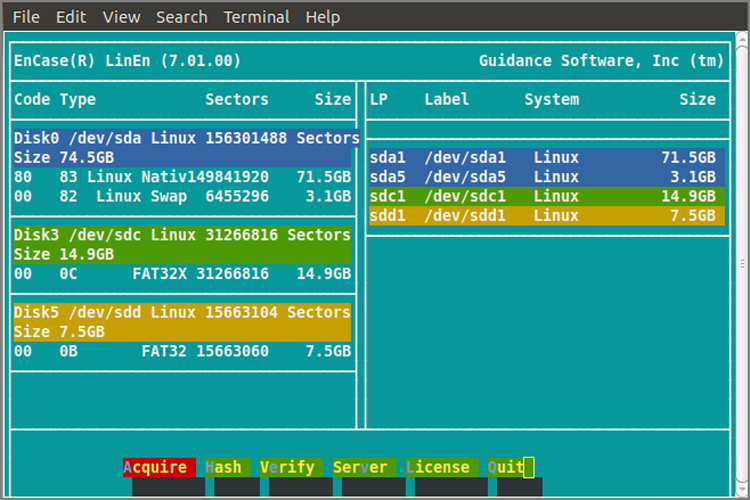
10. You can conduct an MD5 hash using the Hash tool. With this you can hash a physical drive or logical volume.
11. To acquire an image, press A or use the Tab key to go to Acquire and press Enter. What you see next is a choice of physical and logical devices available to image, as shown in Figure 4-41. However, they appear as Linux sees them. Therefore, you’ll need to know how you connected your device and its properties such as its size, volume name, and so forth, to identify it. If you are accustomed to Linux, it’s a snap. If you are accustomed to Windows, it will require some learning on your part. Select your device, and press Enter.
Figure 4-41: Choose a drive to acquire in LinEn, noting that devices use the Linux naming conventions.
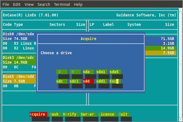
12. You are next prompted for the path for your evidence file. Although this prompt is the same as EnCase for DOS, the path you type must satisfy the Linux path requirements and must be case sensitive as well. Recall that you created a directory on your storage drive (FAT32) and called it /cases/casename/evidence. To address that in Linux, you need to prefix it with the path to the mount path; it would appear as /mnt/winfat/cases/casename/evidence/USBTD001, with USBTD001 representing the name of the evidence file you want to create.
13. From this point forward, all screens are the same as you found in EnCase for DOS with one exception. In EnCase for DOS, the block size was fixed at 64 sectors because of DOS limitations, and changing the block size was not an option. In Linux, however, it is an option. After you enter your Maximum File Size or file chunk size option, you will have the opportunity to adjust the block size. The same pros and cons previously discussed for block sizes apply; they apply equally to the Error Granularity setting, which immediately follows the Block Size option.
14. Once you’ve entered the Error Granularity setting, LinEn starts acquiring, providing you with the same acquisition status screen you saw in EnCase for DOS. When the image is complete, you get another window telling you it is done, the name and path of the file, and the time it took to acquire.
15. You have the option in LinEn to acquire via network cable. (Thankfully, there is no parallel cable option!) The physical setup is the same: you connect your Linux imaging machine (lab or suspect) to a Windows machine running EnCase using a network crossover cable. At this point, the process is the same as in EnCase for DOS. If you can’t make a connection, exit LinEn. To make things work, you may have to assign an IP address to the Linux platform and different host IP on the same logical network for the Windows machine. I covered the method of changing the Windows IP and network settings in “Steps for Network Acquisition” earlier in this chapter. Refer to that information, and set the Windows machine to 10.0.0.50 and a subnet mask of 255.0.0.0. For the Linux machine, do the following:
1. At the console command line, type ifconfig eth0.
2. If no IP is assigned or one is assigned that doesn’t fall in the 10.0.0.x network, you need to assign one. Type ifconfig eth0 10.0.0.1 netmask 255.0.0.0, and press Enter.
3. Type ifconfig eth0 again, and check to make sure your settings are there (if you belong to the doubtful lot, like many of are, who like to check and double-check). It’s like a carpenter who measures three times and cuts once!
4. Restart LinEn, and start the server. Restart EnCase on Windows, and follow the steps for making a network cable acquisition. When you have to choose devices in EnCase for Windows, the list of available devices will again be as Linux sees them and names them. Everything else is the same.
HPA and DCO in LinEn
LinEn supports direct access mode if the underlying Linux distribution supports it. If it doesn’t, you won’t see it. Thus, whether HPA or DCO can be seen and acquired by LinEn depends on your Linux distribution.
Remember that what is supported in the way of attached devices (USB, FireWire, SCSI, and so forth) depends completely on the Linux distribution being used. For the best device support, use the most current distributions of Linux, and update them with the most current version of LinEn.
Enterprise and FIM Acquisitions
EnCase Forensic allows you to preview and acquire over a network crossover cable, with the length of the crossover cable setting the limit as to how far apart the machines can be. With the EnCase Enterprise (EE) and EnCase Field Intelligence Model (FIM; its end of life is with EnCase 6) editions of EnCase, the preview and acquisition occur over the network and can occur over thousands of miles if need be. In a later release of EnCase 7, EnCase Forensic will have the ability to preview and acquire one machine at a time over the network. The only practical limitation is the speed of the connection. This method of preview and acquisition cuts travel expenses drastically and enables incident-response time to be cut to near zero levels, if the systems are in place when the incident occurs.
Another distinction between the network cable preview and acquisition and one done with EE or FIM is that with EE and FIM, the target system is live and running its native operating system. As such, the target machine can be examined with or without the user’s knowledge and the live system-state data (volatile data) can be previewed and captured. By capturing the volatile system-state data, examiners can analyze running processes, network connections, logged-in users, and much more. Such data is valuable when examining network intrusions, mounted encrypted volumes (if mounted, they can be previewed and acquired intact), cases where malicious code is running, and cases where covert analysis is warranted. The live system-state data is accessed by an optional feature called Snapshot, which is a sophisticated EnScript located, naturally, in the EnScript section.
This is not intended to be a tutorial on how to configure, administer, and use EE or FIM. That involves two weeks of training and is beyond the scope of this book. Rather, the intent here is to familiarize you with the function and features so you can understand them well enough to intelligently decide on their applicability in any given situation should the need arise to deploy them.
The major differences between the EE version and the FIM version are in licensing and configuration. The FIM version can be licensed only to law enforcement and military customers. The EE version is, essentially, for everyone else needing EE/FIM features. Additionally, the FIM was licensed for only one simultaneous connection, whereas EE starts at three connections and goes up depending on customer need and licensing agreements. The Snapshot feature that captures live system-state data is a separate license and is enabled for all connections when purchased.
To understand the configuration differences, you must first understand how EE is configured and functions; only then can you appreciate how FIM differs from EE. There are three major components of an EE/FIM system. As shown in Figure 4-42, those components are the examination machine, the servlet node (target machine), and the SAFE.
Figure 4-42: Schematic of EnCase Enterprise. Note the three components: the examination machine, the servlet node (target machine), and the SAFE.
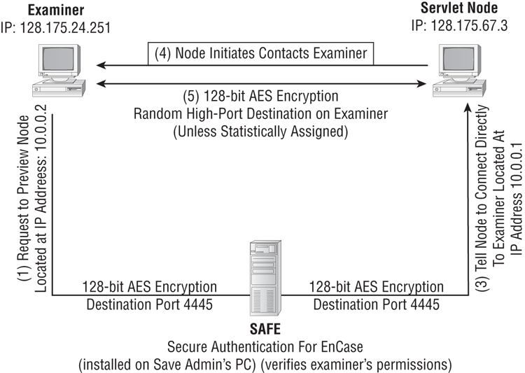
As the examiner, you have EE on your examination machine. Your target machine (servlet node), however many miles away, must have a servlet installed and running. A servlet is a small piece of code that places the target machine in a server mode listening on the network for a connection. The servlet is thus a server that will communicate with your examination machine, and it must also communicate with yet another machine called a SAFE. SAFE, as explained earlier, stands for Secure Authentication for EnCase. The SAFE is not technically necessary for a network forensic connection, but it is necessary to place a high-level of security and supervisory control over the entire process.
The function of the examination machine and the servlet node (target machine) are self-evident, because they are analogous to the two machines in the network cable acquisition model. What is slightly different, however, is the installation of the servlet. The servlet acts as a secure network connection to the examination machine, after first authenticating through the SAFE. The servlet allows EE to have physical access to the target computer at a level below the operating system. When installed, the servlet listens on port 4445, but you can configure it for other ports when you create and install it.
The servlet can be preinstalled by a variety of methods, or it can be installed when needed. You can be physically present for the installation, or you can deploy the servlet remotely by using one of many remote administration tools or “push technologies,” such as Active Directory. It can be done manually or automated with scripts. To install the servlet on Windows systems, you must have administrator rights. On Linux/Unix, you must have root-level privileges. Guidance Software has published a small manual, available on its website, that deals strictly with deploying servlets.
The SAFE, the new piece in the model, is a stand-alone machine that stands between, initially, the examination machine and the servlet node. The SAFE is usually administered by, or at the direction of, a high-level person in the organization, typically at the level of the chief information officer or equivalent.
This SAFE administrator controls what servlet nodes the examiner can access and is dubbed the keymaster. The granularity of control is very coarse or very fine. The controls can determine the days and times an examiner can access a given node. Further, the controls can determine the level of functions permitted to the examiner. For example, an examiner can be limited to previewing only and not permitted to acquire or copy files.
Each examiner must be added to the list of examiners for each SAFE and is assigned keys for authentication and encryption. Before a node can be accessed by an examiner, the keymaster must log on to the SAFE and add the servlet node to the list of nodes the examiner may access, along with any limitations on that access. Furthermore, all traffic between any devices in the EE system is encrypted using 128-bit Advanced Encryption Standard (AES) encryption. Thus, the SAFE provides supervisory oversight, serves as an authentication gateway, and facilitates the encryption of the network connection.
When an examiner wants to connect to a target machine, the examiner communicates with the SAFE with a request to do so. If the requested connection and access is permitted by the established rules, the SAFE communicates with the target node. The SAFE tells the target node to communicate directly with the examination machine. The servlet node (target machine) then communicates directly with the examination machine, and the session takes place with whatever controls may be in place as directed by the SAFE. This connection is depicted in Figure 4-42.
Firewalls will have to be configured to enable this traffic to pass. Any host-based firewall on a servlet node will also have to be configured to allow the servlet connection to pass. As a fail-safe, if for any reason the servlet node can’t connect directly to the examination machine, the connection may route to the examination machine through the SAFE. Although the connection will be somewhat slower, it will, nevertheless, occur. With EnCase 6, the servlet has the ability to initiate a timed, unsolicited, outbound connection to the SAFE for snapshot purposes. This is designed for users who are operating behind a firewall.
The FIM was basically an EE system with one slight configuration modification. With the FIM, the SAFE is located directly on the examiner’s machine, usually a laptop, and the examiner and the keymaster are the same person. Because there is no third-party keymaster overseeing the connections, the FIM has become a very powerful tool. It was developed for law enforcement and military applications. EnCase Forensic 7.04 is planning to continue this functionality.
Figure 4-43 shows the FIM configuration. If you look carefully, the major difference is where the SAFE is located. In the EE, the SAFE is located on the SAFE administrator’s PC. In the FIM, the SAFE is located on the examination machine, removing the third party altogether. Otherwise, they function in the same manner.
Figure 4-43: FIM schematic with SAFE located on examiner’s machine. Compare this to EE schematic in Figure 4-42, where SAFE is a separate machine controlled by the SAFE administrator (keymaster).
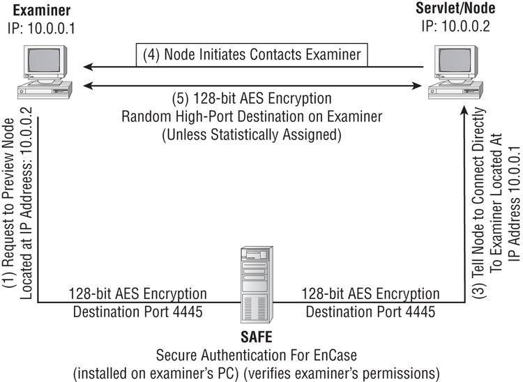
In law enforcement and military applications, the FIM is often connected to a target host (servlet node) directly with a crossover cable. Of course, this differs from the network cable acquisition since the target host is live and the servlet is installed directly by the examiner. Usually, with most home machines, the user has administrator rights and servlet deployment is a minor task. When the connection is made, the examiner has access to the storage media on the target host plus the live system-state data.
The FIM is not limited to a crossover cable connection and can also connect to any network machine on which the servlet is deployed. In law enforcement and military use, it is ideal for surreptitious remote previewing and acquisitions, with proper search authority having been secured.
Another extremely useful application of the FIM is when conducting previews or acquisitions on business servers that can’t be shut down. It’s a simple matter for the examiner to connect to the network on which the server resides. The examiner next deploys the servlet on the target server. With that done, the examiner logs in as keymaster and adds the IP address of the target server to the list of nodes the examiner can access. The examiner logs off as keymaster and then logs back into the SAFE as the examiner. At this point, the examiner can connect to the target server and conduct a preview or acquisition as needed. All storage media is available, as is the live system-state data. The examiner completes the job at his or her leisure, the server stays up, and business goes on as usual.
EE and FIM are very powerful and flexible tools. As live forensics has become mainstream, their value to the industry has been realized.
![]()
With the release of EnCase 7, Guidance Software has discontinued the FIM product line. Current FIM users will be channeled into the EE product line, which effectively provides the same result with the same functionality. Therefore, EnCase 6 will be the last release that has the FIM module and therefore for which the foregoing discussion applies. Naturally, EnCase 7 Enterprise will continue to develop and offer new features. Guidance Software will develop EnCase 7 such that a future release of EnCase 7 (expected for 7.04) will have provide FIM-like functionality as a standard feature!
EnCase Portable
While EnCase Portable has many features, I am not going to attempt to cover them all but will instead cover its acquisition features. I’ll cover the use of it to acquire from EnCase Portable as a boot device. With that knowledge, using it to make a live acquisition is a mere subset of doing so from boot.
I’ll assume you have EnCase Portable installed and otherwise ready to use. If you are going to use EnCase Portable to acquire a hard drive or sizeable device, one of the first considerations is to have media prepared to receive or store the image. With EnCase Portable, there is one added step, which is to prepare that device to work with EnCase Portable.
![]()
The EnCase Portable model is a triage and evidence collection tool that is currently in its version 3 release. EnCase Portable serves many useful functions. It can function in a live mode where it can be used to collect data from live Windows machines. That data can be files, volatile data (snapshot), RAM image, or a live drive. It can also be used to boot from USB (when supported) or from a CD. When used as a boot device, it can be used to acquire logical or physical devices. In the latter mode, it can also boot Macintosh systems, including those hard-to-image MacBook Air models. In most cases, the Macintosh systems will have to be booted with the CD and not the USB, but it can be done very nicely.
When using a CD to boot a MacBook Air, you’ll find that not just any external CD drive will work. Rather, you’ll need the one made by Apple for the MacBook Air in order to boot from a CD. Apple likes to give its hardware a lobotomy, at times, when it comes to working with non-Apple hardware.
To prepare the media, you’ll need to attach the sterile media to the Windows system onto which EnCase Portable has been installed. Next, you start EnCase and open your case. The next step is to open the EnScript menu and run the Portable Management EnScript, as shown in Figure 4-44. When the Portable Management menu opens, go to the Storage tab. In that tab, you should see, perhaps among others, the sterile media that you attached. Select that device, right-click it, and click Prepare, which is shown in Figure 4-45. EnCase Portable will quickly prepare the drive, and you will see a Boolean dot in the Prepared column, as shown in Figure 4-46.
Figure 4-44: Portable Management EnScript
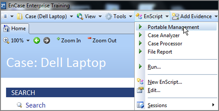
Figure 4-45: Select drive, right-click, and click Prepare
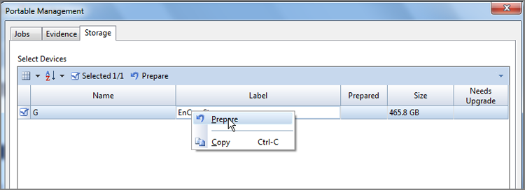
Figure 4-46: Drive prepared to receive evidence from EnCase Portable
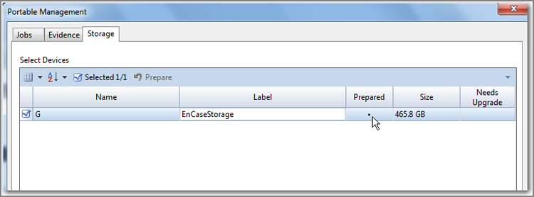
With the drive prepared to receive evidence from EnCase Portable, you should next simply exit the Portable Management tool, exit EnCase, and remove the drive. Next, you will boot the suspect computer with either the EnCase Portable Codemeter USB device or the CD. If you use the latter, you must also have the Codemeter attached for the license to be available; otherwise, EnCase Portable won’t run. By now, you know the precautions and steps involved in booting a suspect machine using forensic boot media (CD or USB), so I won’t revisit those steps other than to say that you must address the boot order and take control of the process to ensure booting from your media.
In this example, I’ll use a USB bootable machine and insert the Codemeter USB and start the machine. You should not have any other USB devices inserted when booting from the USB dongle. Once the boot starts from the USB, you see the Windows splash screen appear. As long as you have taken the proper steps and are actually booting from the USB device, don’t be alarmed as EnCase Portable is booting under Windows “BARTPE.” Next, you’ll see the EnCase Portable desktop background and messages from EnCase while it searches for devices and reports to you, as shown in Figures 4-47 and 4-48. As EnCase begins its search for drives, connect your target media that is prepared to receive evidence from EnCase Portable.
Figure 4-47: EnCase Portable searching for devices after Windows boot
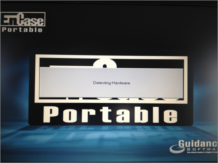
Figure 4-48: EnCase Portable allowing only EnCase-specific write-protected drives
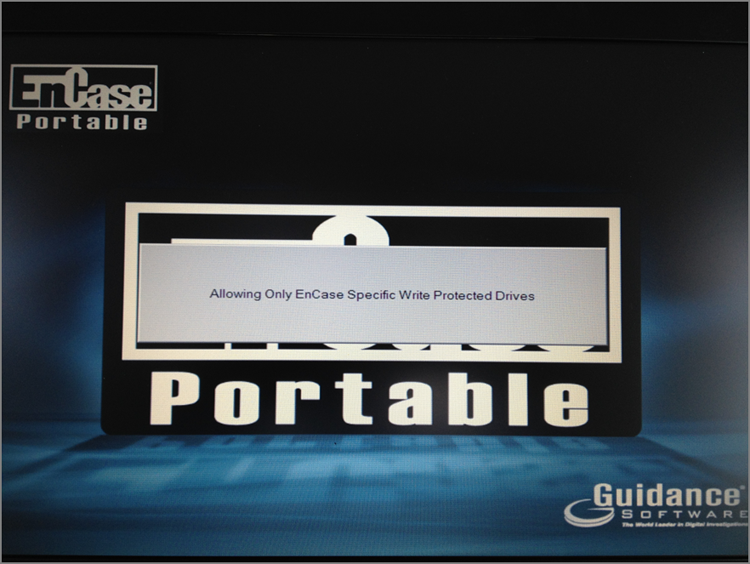
Once EnCase Portable has polled the devices, it loads, and you are presented with a menu of tasks. You can choose from among prepared jobs or create your own. In this example, I’m simply going to choose Create A Copy Of Drive Or Memory and click Run Job, as shown in Figure 4-49.
Figure 4-49: EnCase Portable menu from which you choose a task and run it
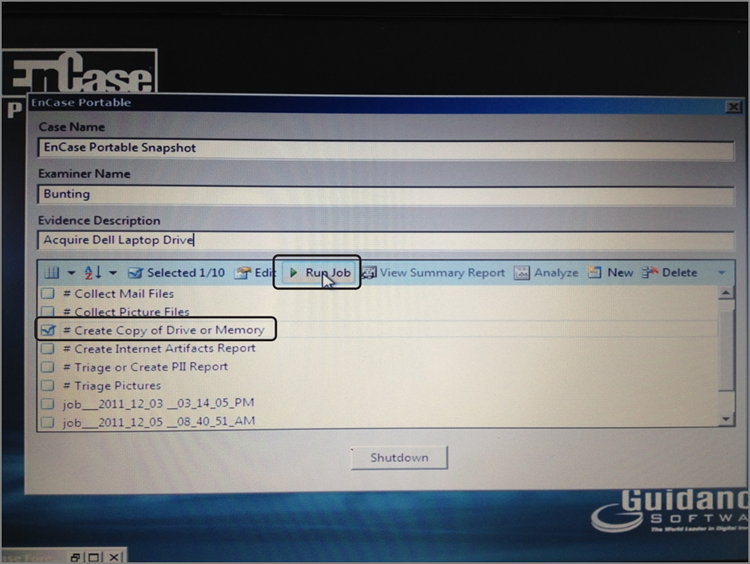
As the task runs, you’ll receive a message that EnCase Portable is searching for drives. When it is complete, you will see the Acquisition menu listing the available drives to acquire. You should not see your target media in this list. In this example, shown in Figure 4-50, select the logical C volume with a blue check, select Verify Acquisition (on by default), and click OK to start. Since you prepared and attached your target drive that is intended to receive the image, EnCase detects this drive in the background and, upon starting the acquisition, places the image on that drive automatically without any prompting. In Figure 4-50, you can see at the top (I’ve circled it) that EnCase Portable has detected and is reporting the amount of storage available for my collection, which in this case is 465 GB.
When the acquisition task has completed, you’ll see the status change in the Status menu, as shown in Figure 4-51. To exit EnCase Portable at this juncture, close the Status menu, which will leave you viewing the EnCase Portable main menu, as shown in Figure 4-52. At the bottom of this menu, click Shutdown, which is circled, and EnCase Portable and Windows will shut down completely.
Figure 4-50: EnCase Portable Acquisition menu from which you select the devices to acquire. Note the amount of storage drive free space that is being reported.
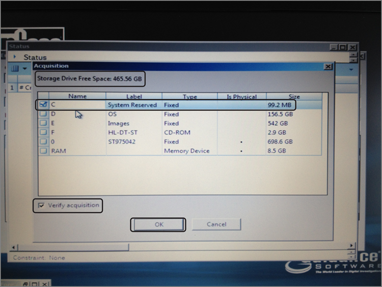
Figure 4-51: Status menu reporting that the acquisition has completed
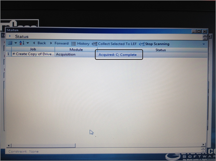
Figure 4-52: Shutting down EnCase Portable and Windows from the EnCase Portable main menu
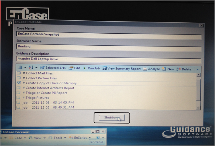
At this point, your suspect machine has been shut down, and you can remove your EnCase Portable Codemeter device and the storage media containing the image you collected. The image can be transferred manually to your EnCase examination machine, or you can use the Portable Management EnScript to handle the task. To use the latter method, connect your EnCase Portable storage drive (containing acquisition image), start EnCase, open your case, and run the Portable Management EnScript, as shown previously in Figure 4-44.
When the Portable Management menu displays, switch to the Evidence tab, which is displayed in Figure 4-53. The Portable Management EnScript will have polled for EnCase Portable storage devices and will display them on the Select Device drop-down menu. Since, in this example, I had only one connected, it was already being displayed along with the name of the task I ran to collect the evidence, which is Create Copy Of Drive Or Memory (circled). With this task selected in the left pane, the evidence files associated with that task are displayed in the right pane.
In this example, I’m selecting the acquired image in the right pane (circled and selected with a blue check) to be copied into the case. At the bottom, you define the path to copy the evidence to with the Copy Evidence To dialog box (circled). Also in the bottom section, there are two copy options. You can delete the evidence on your storage drive after it is copied to your examination machine. In this example, I’m not selecting this option because best practices call for examining a copy and storing the original in a secure location. I am, however, selecting the other copy option, which is to add the evidence to the case. When you have selected all the options you deem appropriate, you click Copy (circled) on the Collected Evidence toolbar to initiate the action. When the copy task completes, the completed job details are displayed in a status report, as shown in Figure 4-54.
Figure 4-53: Portable Management dialog Evidence tab from which evidence is copied into your open case
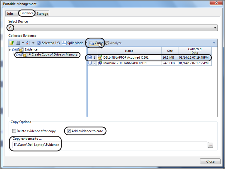
Figure 4-54: EnCase Portable status report
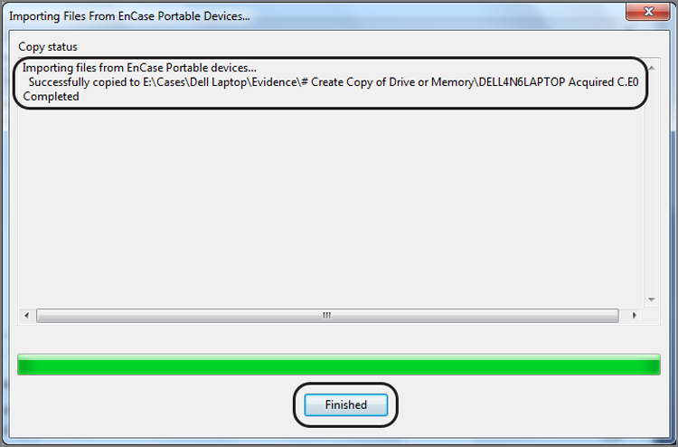
When done, click Finish to close the status report, and click Close to close the Portable Management EnScript. If you browse the evidence in your case, you will see the evidence item already added to the case, since we selected that option, which saved us many steps. Figure 4-55 shows the image after being added to the case and opened.
Figure 4-55: Image acquired with EnCase Portable being displayed in EnCase after being added to a case using the Portable Management tool
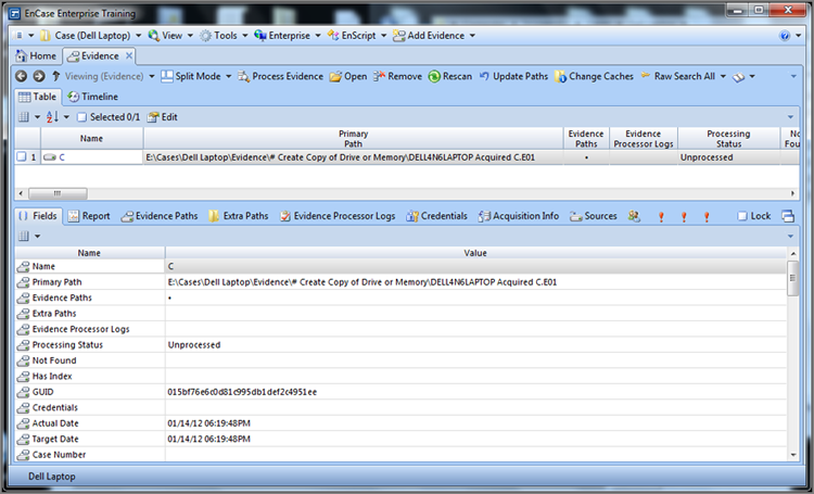
![]()
EnCase Portable can extend the reach of your expertise into the field. You can direct nonexpert field personnel to act on your behalf using this tool with minimal instruction, since the tasks are canned or prepared in advance in the lab. In this manner, forensic examiners can focus on examination and analysis and less on collection tasks, making best use of scarce and valuable resources.
Helpful Hints
As you encounter various devices, here are some suggested acquisition solutions:
· If you encounter a floppy disk, flip the write-protect notch to read-only and acquire in EnCase for Windows on a system where the floppy drive has been tested for its ability to write protect. Alternatively, you could do a DOS acquisition, but there’s usually no need.
· If you encounter a Zip or Jaz disk, use an IDE Zip or Jaz drive, and acquire in EnCase for DOS. You will need the GUEST.EXE file to mount the Iomega drivers. The easiest solution is to download the Zip-booter boot disk image from the Guidance Software website, update it with the latest EN.EXE, and you are set.
· If you encounter a CD/DVD, you can safely image it in Windows. You may encounter difficulties with some CD/DVD file systems. An alternative in these cases is to use CD Inspector, create a Zip image file, and bring the Zip file into the EnCase environment. This functionality is new starting with EnCase 5.
· If you encounter USB Flash media, you can usually image it in Windows by flipping the write-protect switch and doing so in combination with the registry setting that makes USB devices read-only. This setting is available only in Windows XP SP2 or newer. If neither of these write-protect features is an option, the ENBD/ENBCD has a feature to load DOS USB drivers. EnCase for DOS can then be used. Another option is to use LinEn on a version of Linux that has support for your USB devices, making sure you first disable automounting of the file system as previously discussed. Another option is to use the FastBloc SE. Using this module, USB, FireWire, and SCSI devices can be quite easily acquired in a forensically sound manner.
Summary
This chapter covered the many facets of acquiring digital evidence. I covered the process by which you control the boot process by modifying the boot order in Setup and modifying boot disks so that any calls made to the hard drive are redirected to the boot disk. You examined three methods of creating EnCase boot disks within EnCase.
After understanding the process and making EnCase boot disks, I discussed the reasons why EnCase boot disks are needed despite advances in write-blocking technology allowing acquisitions in Windows. For example, you may encounter geometry mismatches between legacy and modern BIOS code. You may encounter proprietary security schemes that marry hard drives to chips on the motherboard. You may also encounter HPA or DCO areas of the drive that can’t be seen by the BIOS in Windows. Any of these conditions warrant booting with EnCase for DOS or LinEn in Linux to be able to access the drive directly through the ATA controller.
I detailed the process of booting a computer with EnCase boot disks using a carefully controlled sequence. Before connecting the target drive, you must configure the system to boot from the EnCase boot disk and make certain it works before reconnecting the target drive.
Drive-to-drive acquisitions occur when the storage media and the target media are mounted on the same machine. I detailed how to use EnCase for DOS for these acquisitions, based on the foundation I laid for creating EnCase boot disks and booting from them. I discussed the importance of preparing storage media formatted to FAT32, with a unique volume label and with a preconfigured directory path for the EnCase evidence files. I showed how to account for all sectors on a drive and how to switch to the Direct ATA mode when encountering HPA or DCO areas, usually indicated when all sectors can’t be seen by the BIOS.
Network cable acquisitions occur between two machines connected by a network crossover cable. One machine is running EnCase for Windows, while the other machine is running EnCase for DOS or LinEn under Linux. The target host machine runs EnCase (DOS) or LinEn in a server mode first. Once that machine is waiting to connect, the EnCase for Windows machine is started. When choosing the devices to acquire, the network crossover option is selected, which then connects with the waiting server, and a network connection is established over which previewing or acquisition occurs.
Network cable acquisitions can be used to overcome HPA or DCO issues. They are relatively fast acquisition methods and even faster using gigabit NIC cards on both ends and LinEn as the tool. In lieu of a network cable, a parallel cable connection can be substituted. Parallel cable transmission rates are horribly slow, and network cable is much faster and preferred. Parallel cable acquisitions aren’t available in LinEn and therefore are available only through EnCase 5.
While discussing network cable acquisitions, I detailed the many acquisition options in EnCase for Windows. You examined the pros and cons of adjusting block sizes and error granularity, both of which are new starting with EnCase 5. You can increase block sizes and make error granularity less coarse and increase acquisition speeds. The downside is possible data loss when encountering errors during acquisition or later if data becomes corrupt in the evidence file.
FastBloc/Tableau units are hardware write-blocking devices that block writes to IDE drives or SATA drives if connected via an IDE/SATA bridge. Models are also available to write-block SCSI and SAS drives. You examined how FastBloc/Tableau integrates with EnCase or as a stand-alone device within Windows.
FastBloc has been available in five hardware models and is still used extensively in the field and in labs:
· FastBloc Classic has a SCSI interface with the host.
· FastBloc LE has an IDE interface with the host.
· FastBloc FE has a USB or 1394a interface with the host.
· FastBloc2 FE has a USB or 1394b interface with the host and interfaces with the target using a series of adapters for the various types of media that are rapidly evolving.
· FastBloc2 LE, the laboratory version of the FE, is intended to be mounted in the host computer forensic computer. The FastBloc shows as a special icon with a blue (EnCase 5) or green square (EnCase 6 & 7) around the physical device. It also shows as Write Blocked with a Boolean indicator for true. FastBloc also is reported in the acquisition details listed on the Report tab for the acquired image.
· With the acquisition of the Tableau company by Guidance Software, the FastBloc product line was discontinued and in its place are several field and laboratory (bay-mounted) models
LinEn is EnCase for Linux, which is new beginning with EnCase 5. Linux affords many advantages over DOS because Linux is a 32-bit OS (optionally 64-bit), while DOS is a 16-bit OS. Linux controls how devices are mounted and whether file systems are mounted; if file systems are mounted, they can be mounted as read-only. I detailed how to configure mainstream Linux not to automount file systems and how to change the runlevel so that Linux starts in the console mode and not the GUI mode. Using the fdisk -l command, you can see what devices are available; using the mount command, you can see what file systems are mounted and how. Using the Linux naming conventions, hda2 is the second partition on the primary master, while hdd1 is the first partition on the secondary slave. When running LinEn, you can acquire, hash, or run in the server mode for network cable acquisition with nearly the same interface options as EnCase for DOS.
EnCase Enterprise and EnCase FIM can preview and acquire target systems (servlet nodes) over a network connection with no limitations on distance. If the Internet can reach the target, you can reach it with EE or FIM. FIM is for law enforcement or military customers, and EE is for all others. The three components of the EE or FIM system are the examiner machine, the servlet node (target host), and the SAFE. The SAFE authenticates the connection, acts to limit and supervise the process, and facilitates the encrypted connection. With EE, the SAFE is on a separate PC administered by a SAFE administrator known as the keymaster. With FIM, the SAFE resides on the same PC as the examination machine, making the examiner and keymaster the same person. In addition to previewing and acquiring a live host, EE or FIM can capture live system-state data using the Snapshot feature.
EnCase Portable is a field device consisting of a bootable USB Codemeter/storage device, additional USB storage media, a USB hub, an installation DVD, a bootable CD, and a carrying case. EnCase Portable is used for triage and collection of evidence and can be used by nonexpert field personnel. Among the many collection tasks available, EnCase Portable can acquire hard drives at either logical or physical levels. These acquisitions can be carried out against lives devices or by booting suspect machines using either USB or CD boot devices. If booting from the CD, the USB Codemeter must also be attached. Before media can be used for storage by EnCase Portable, it must first be prepared using the Portable Management tool.
![]()
The EnCE test under EnCase 6 will contain questions pertaining to EnCase DOS boot disks. Beginning with the EnCase 7 EnCE test, examiners will no longer be tested on EnCase DOS boot disks and related concepts.
Exam Essentials
Know how use the LinEn for Linux tool. Be able to explain the various conditions that would warrant a LinEn acquisition. Explain the importance of modifying Linux to disable the automatic mounting of the file system upon boot. Explain why it is important to boot Linux to the console mode and how to configure this change. Explain what acquisition options are available in LinEn. Understand how Linux names devices and partitions.
Understand why and how an EnCase boot disk is made. Know where the tools are located to create an EnCase boot disk. Be able to explain the steps involved in creating an EnCase boot disk and also how to update an EnCase boot disk with an updated version of LinEn. Explain how Linux achieves write blocking and the importance of using forensically sound distributions of Linux for this purpose.
Understand how to boot a computer with an EnCase boot disk. Be able to explain the various conditions that would warrant booting a computer with an EnCase boot disk. Explain the process of preparing the target host computer for a safe boot using the EnCase boot disk. Know how to change the boot order in Setup and why this step is important. Describe each step in booting the computer using an EnCase boot disk and the importance of each step.
Know how to do a disk-to-disk acquisition. Be able to explain the various conditions that would warrant a disk-to-disk acquisition. Be able to explain the difference between the BIOS and Direct ATA modes, how to switch between them, and why this would be necessary. Know how to adjust the Error Granularity setting and be able to explain the effects of changing the setting. Be able to explain the connections and steps necessary to conduct a disk-to-disk acquisition using EnCase for DOS.
Know how to conduct a network cable acquisition. Be able to explain the various conditions that would warrant a network cable acquisition. Know what kind of cable is required for this acquisition, and explain the difference between this cable and a regular network cable. Explain the importance of controlling the boot process on the target host. Explain the steps involved in booting the target host and making the connection to EnCase for Windows. Describe the various acquisition options. Understand how to adjust the block size, and explain the pros and cons of changing it. Understand which evidence file properties you can change by reacquiring. Explain why the MD5 hash does not change when you reacquire and change any of these properties, unless you change the number of sectors.
Know how to conduct a Tableau acquisition. Know the different Tableau models, and explain how their host connections are different. Explain how to connect the FastBloc to the host and to the target drive. Describe the process by which Tableau is powered on and its attached drive is mounted in Windows. Know what the Tableau icon looks like and where and how its “write-block” status is reported or indicated in EnCase. Describe how Tableau can be used as a stand-alone write-blocking device by which to use third-party tools to examine the drive in Windows without EnCase. Understand the disk-caching problems associated with using FastBloc with Windows 98/Me.
Understand EE and FIM configuration and capabilities. Know the three components in EE or FIM systems, and explain how they function. Understand under what circumstances an EE or FIM would be valuable to an investigation. Understand what types of data that EE or FIM can capture that other EnCase models can’t. Explain volatile system-state data and its importance to an investigation. Explain how EE and FIM differ.
Understand EnCase Portable configuration and capabilities. Know how to prepare storage media using the Portable Management tool. Describe how to boot a suspect machine using a USB or CD device to boot the EnCase Portable software. Describe how to acquire a device and subsequently transfer the acquired image to an open case. Understand how EnCase Portable can be used by nonexpert field personnel under the direction of an examiner to triage and collect evidence in the field.
Review Questions
1. When acquiring a hard drive using a Linux boot disk with LinEn, what would be the cause of EnCase (LinEn) not detecting partition information?
A. The drive has been FDisked and the partition(s) removed.
B. The partition(s) are not recognized by Linux.
C. Both A and B.
D. None of the above.
2. LinEn contains a write blocker that protects the target media from being altered.
A. True
B. False
3. As a good forensic practice, why would it be a good idea to wipe a forensic drive before reusing it?
A. Chain-of-custody
B. Cross-contamination
C. Different file and operating systems
D. Chain of evidence
E. No need to wipe
4. If the number of sectors reported by EnCase does not match the number reported by the manufacturer for the drive, what should you do?
A. Suspect HPA.
B. Suspect DCO.
C. Use Tableau or FastBloc SE to access the sectors protected by HPA or DCO.
D. Boot with LinEn in Linux.
E. All of the above.
5. When acquiring digital evidence, why shouldn’t the evidence be left unattended in an unsecured location?
A. Cross-contamination
B. Storage
C. Chain-of-custody
D. Not an issue
6. Which describes an HPA? (Choose all that apply.)
A. Stands for Host Protected Area
B. Is not normally seen by the BIOS
C. Is not normally seen through Direct ATA access
D. Was introduced in the ATA-6 specification
7. Which describes a DCO?
A. Was introduced in the ATA-6 specification.
B. Stands for Device Configuration Overlay.
C. Is not normally seen by the BIOS.
D. It may contain hidden data, which can be seen by switching to the Direct ATA mode in EnCase for DOS.
E. All of the above.
8. At which user level must the examiner function when using LinEn?
A. Administrator
B. Admin
C. Root
D. Any user
E. None of the above
9. Reacquiring an image and adding compression will change the MD5 value of the acquisition hash.
A. True
B. False
10. When reacquiring an image, you can change the name of the evidence.
A. True
B. False
11. Which of the following should you do when creating a storage volume to hold an EnCase evidence file that will be created with LinEn? (Choose all that apply.)
A. Format the volume with the FAT file system.
B. Give the volume a unique label to identify it.
C. Wipe the volume before formatting to conform to best practices, and avoid claims of cross-contamination.
D. Create a directory to contain the evidence file.
E. Format the volume with the NTFS file system.
F. All of the above.
12. In Linux, what describes hdb2? (Choose all that apply.)
A. Refers to the primary master
B. Refers to the primary slave
C. Refers to hard drive number 2
D. Refers to the second partition
E. Refers to the secondary master
13. In Linux, what describes sdb? (Choose all that apply.)
A. Refers to an IDE device
B. Refers to a SCSI device
C. Refers to a USB device
D. Refers to a FireWire device
14. When acquiring USB flash memory, you could write-protect it by doing what?
A. Engaging the write-protect switch, if equipped
B. Modifying the registry in Windows XP SP2 (or higher) to make USB read-only
C. Using ENBD/ENBCD USB DOS drivers and having EnCase for DOS “lock” the Flash media
D. Using LinEn in Linux with automount of file system disabled
E. Using FastBloc SE to write block USB, FireWire, SCSI drives
F. All of the above
15. Which are true with regard to EnCase Portable? (Choose all that apply.)
A. Storage media must be prepared using the Portable Management tool before it can be used by EnCase Portable.
B. If booting using the EnCase Portable Boot CD to boot, the EnCase Portable dongle must also be connected so that the license can be accessed.
C. The EnCase Portable can triage and collect evidence in a forensically sound manner from live machines or to do so in a boot mode.
D. The EnCase Portable can be configured with custom tasks created by the examiner using the Portable Management tool.
16. LinEn can be run under both Windows and DOS operating systems.
A. True
B. False
17. When using LinEn, the level of support for USB, FireWire, and SCSI devices is determined by what?
A. The drivers built into LinEn
B. The drivers provided with the ENBCD
C. The distribution of Linux being used
D. A and B
E. None of the above
18. How should CDs be acquired using EnCase?
A. DOS
B. Windows
19. Select all that are true about EE and FIM.
A. They can acquire or preview a system live without shutting it down.
B. They can capture live system-state volatile data using the Snapshot feature.
C. With EE, the SAFE is on a separate PC, administered by the keymaster.
D. With FIM, the SAFE is on the examiner’s PC and the keymaster and the examiner are the same person.
E. FIM can be licensed to private individuals.
20. Which of the following are true? (Choose all that apply.)
A. LinEn contains no write-blocking capability. Rather, write blocking is achieved by disabling the automount feature within the host Linux operating system.
B. LinEn contains its own onboard write-blocking drivers and therefore can be safely run on any version of Linux.
C. LinEn can format drives to both NTFS and FAT formats.
D. Before using a target drive onto which to write evidence files, LinEn must be used to unlock the target drive and render it writable.
E. LinEn can format drives to EXT2 or EXT3 format.
All materials on the site are licensed Creative Commons Attribution-Sharealike 3.0 Unported CC BY-SA 3.0 & GNU Free Documentation License (GFDL)
If you are the copyright holder of any material contained on our site and intend to remove it, please contact our site administrator for approval.
© 2016-2026 All site design rights belong to S.Y.A.