Mastering Autodesk Inventor 2015 and Autodesk Inventor LT 2015 (2014)
Chapter 12. Documentation
At any point in your design process, you can choose to begin documenting your design with the Autodesk® Inventor® program. Although creating drawings was traditionally something that had to wait until the design was fully complete, there are no such restrictions in Inventor. You can start to develop an annotated 2D drawing file at any point in your process. It is generally recommended, however, that you start documenting as late in the design as possible.
The ultimate goal of this chapter is to illustrate how you can use the Drawing Manager in Inventor to generate traditional 2D annotated drawings. You can then output your documentation in a variety of file formats, including DWF and PDF.
In this chapter, you'll learn to
· Create and maintain drawing templates, standards, and styles
· Generate 2D drawing views of parts, assemblies, and presentations
· Annotate drawing views of your model
Using the Drawing Manager
Once you have created your 3D design, you can choose to document it with conventional 2D orthographic drawing views and traditional drafting tools. This kind of documentation is created in the Drawing Manager environment.
These high-level Drawing Manager tasks are discussed in the following sections:
· Creating templates and styles
· Utilizing drawing resources
· Editing styles and standards
· Creating drawing views
· Annotating part drawings
· Annotating assembly drawings
· Working with sheet-metal drawings
· Working with weldment views
· Working with iParts and iAssembly drawings
· Sharing your drawings outside your workgroup
Creating Templates and Styles
Although several drawing templates are installed with Inventor, before you begin to document your own designs and models, you should create your own custom template or templates to best meet your needs. This is because most users have to adhere to a specific set of drafting standards dictated by their company, customer, or vendor specifications. These standards are typically derivatives of one of several international drafting standards such as ANSI, ISO, or DIN. Therefore, Inventor installs with a set of templates and drafting styles configured for the following international standards:
· ANSI (both Imperial and metric units)
· BSI
· DIN
· GB
· GOST
· ISO
· JIS
When creating your own custom template, it is sometimes best to start with a standard template that closely meets your requirements and modify the styles already found within it as needed. At other times it might be best to create a template from a “clean” template file that contains no styles and create them yourself.
Creating templates in the Drawing Manager is not unlike creating templates in other applications. The primary difference is that many applications use a special file format for template files, whereas Inventor uses the same file format but uses a folder location to designate all files within the template location as templates. As a result, you can use any IDW or DWG file as a drawing template; you just need to save it in the template location.
To create a drawing template from an existing, Autodesk-provided template, follow these general steps:
1. Click the New File button from the Get Started tab.
2. Choose an IDW or DWG template that is close to your needs (for instance, you might select the DIN.idw file if your company uses the DIN standard).
3. Click the Inventor button (the large I in the upper-left corner) and choose Save As![]() Save Copy As Template.
Save Copy As Template.
4. Create a new folder for your custom template location.
5. Rename your custom template to a name of your choice.
6. Make changes to the styles and standards as needed and then use the Save Copy As Template option to update the template file.
To create a drawing template from a “clean” template file that contains no styles, follow these general steps:
1. Hold down the Ctrl and Shift keys and click the New File button from the Get Started tab, as shown in Figure 12.1.
2. Select Drawing from the New dialog box and then click the OK button.
3. Click the Inventor button and choose Save As![]() Save Copy As Template.
Save Copy As Template.
4. Create a new folder for your custom template location.
5. Rename your custom template to a name of your choice.
6. Make changes to the styles and standards as needed and then use the Save Copy As Template option to update the template file.
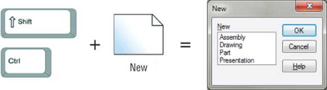
Figure 12.1 Creating a new file with no styles
Understanding Template Locations
By default, Inventor templates are stored in and accessed from C:\Users\Public\Documents\Autodesk\Inventor 2015\Templates. You set the default location initially from the Tools tab by clicking the Application Options button and then selecting the File tab and entering a folder location in the Default Templates box. For stand-alone users working on a local drive, consider using the same location where you store your design projects for your template file location. If you're part of a networked design group, you should create a template folder on a shared network drive and change the default template path accordingly.
The default template location can be overridden on a per-project basis as well by setting the template location in the project file configuration. Keep in mind that if you have a template location set in Application Options and another set in the project file, the project file always takes precedence. Setting the template path in the project and having everyone use the same project file can often be the best way to ensure that all members of the design group are using the same templates.
Standard Templates
If you use the New File drop-down menus to access templates, you should know that these templates are hard-coded to use files named Standard.ipt, Standard.iam, Standard.ipn, and Standard.idw (or .dwg) located at the route of your template location. If you remove or rename the files named Standard, the drop-down menus will not work. Unfortunately, there is no way to point the drop-downs to use a template of a different name. However, if you create a copy of your template files, place them at the root of your template directory, and name them Standard, you can then access your customized templates using the standard drop-down menus.
Choosing a File Format
Prior to Inventor 2008, the IDW file format was the only native 2D file type recognized by Inventor. DWG TrueConnect, introduced with Inventor 2008, enables you to use both DWG and IDW as valid file formats in the Drawing Manager.
Using DWG as your file format enables you to open Inventor DWG files in the AutoCAD® program (or an AutoCAD vertical product such as AutoCAD® Mechanical) without going through a translation process. Although the data you create natively in Inventor cannot be manipulated directly in AutoCAD, all of the Inventor data can be viewed, measured, and printed using conventional AutoCAD commands.
By choosing DWG as your default file format, you allow downstream users of your designs to view the 2D drawing documents in AutoCAD without having to purchase or install Inventor or download the Inventor file viewer. Vendors, customers, or other internal personnel can open the native Inventor DWG file and view, measure, and print the Inventor data, or they can even add AutoCAD data to the file to create a hybrid document that can be viewed quickly and efficiently in either application. AutoCAD users with older versions of AutoCAD might need to download the Autodesk DWG TrueConnect Object Enablers to view the Inventor proxy objects. Use the search phrase TrueConnect Object Enabler to locate the downloads online.
Be Aware of File Size
Although many design departments find the convenience of having their Inventor drawings in DWG format well worth it, you should understand that Inventor DWG files will be larger than Inventor IDW files. The difference in size may vary depending on the content, but differences of up to three times as large can be common. Save a dozen typical drawing files as both Inventor DWG and IDW and compare the sizes yourself to determine which is right for you.
For Inventor users, there is essentially no difference between using DWG and using the traditional IDW file format. The native DWG file includes a Layer 0 in the layer list and an AutoCAD Blocks folder in Drawing Resources. These are the only noticeable differences between the two file formats. An IDW file can always be saved as an Inventor DWG, and vice versa, without any loss of fidelity or data. If there's a good chance of someone wanting to see a DWG version of your Inventor file, you might consider choosing DWG as your default file format. The Task Scheduler in Inventor enables you to batch-convert a set of IDW files into DWG files.
Utilizing Drawing Resources
You should customize three areas of the template to conform to your chosen drafting standards and personal preferences: Drawing Resources, Document Settings, and Styles And Standards.
Drawing resources are simply a collection of reusable sketches and formats that are stored in a drawing file. There are four types of drawing resources: sheet formats, borders, title blocks, and sketched symbols. If you've decided to use DWG as your template format, you'll notice that AutoCAD blocks are also managed as Inventor drawing resources.
Drawing resources are accessed from your drawing browser under the Drawing Resources folder, as shown in Figure 12.2. If you expand the Drawing Resources node, you'll see a folder for each of the drawing resource types listed, and contained in each of the subfolders are drawing-resource definitions. Double-click any drawing resource to place an instance in your drawing.
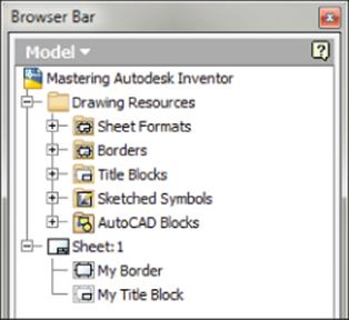
Figure 12.2 The Drawing Resources node in the drawing browser
You can employ several document-management techniques with respect to templates, sheet sizes, borders, and title blocks. Although you could create and maintain separate drawing templates for each sheet size and title block you might need, it's generally recommended that a single drawing template be used to maintain each of these different configurations. In the following sections, you'll take a look at the various drawing resources.
Sheet Size
When you start a new drawing from one of the templates installed with Inventor, a border and title block are already present on the sheet, and the sheet is set to a default size. You can change the default sheet size by right-clicking the sheet in the browser and choosing Edit Sheet from the context menu. For example, if you are using the ANSI (in) template, the default sheet size is C. If you change the sheet size to D, the border on the sheet updates automatically to accommodate the change in sheet size.
To have your templates default to a different sheet size, follow these steps:
1. On the Get Started tab, click the Open button.
2. Browse to your template location and open a drawing file, such as Standard.idw (see the section “Understanding Template Locations” earlier in this chapter).
3. Right-click the sheet in the browser and choose Edit Sheet.
4. Click the arrow in the drop-down box and choose the size or sheet format from the list.
5. Click the Inventor button and choose Save (or press Ctrl+S on the keyboard).
Now when you start a new file from the template, this new sheet size will be active.
Multiple Sheets
If needed, you can add sheets to your template, which is recommended if most of your design documents require more than one sheet. To insert a new sheet into your document, follow these steps:
1. Right-click any blank area on the page and choose New Sheet (or click the New Sheet button on the Place Views tab).
2. Note that this adds the border and title block and the same size sheet as the active sheet.
3. To switch between sheets, double-click the sheet node in the browser.
Multiple Sheet Drawing Files
Use caution when creating multiple sheet sets of a sizable number because performance will likely suffer, depending on the size and complexity of the models you are detailing. Be aware too of “putting all of your eggs in one basket” should a file become corrupted or lost. It is generally considered best practice to create a single drawing for each part number in an assembly, rather than attempting to manage an entire drawing set for an assembly in a single drawing file. However, certain industries approach this aspect of drawing sets differently
Creating a Border
The default border used on the Inventor templates may not meet your needs. To create a new border, you'll first follow these steps to remove the instance of the old border:
1. Expand the sheet node in the browser.
2. Right-click the border instance, and choose Delete.
Doing so removes the instance of the border from the sheet. The border definition is still stored in the Borders folder of the Drawing Resources node. To create a new, custom border in your template, follow these steps:
1. In your template file, expand the Drawing Resources node in the browser.
2. Right-click the Borders folder and choose Define New Border. You might have the option to choose Define New Zone Border, but you'll use a simple border here to explore the steps required. Here is a brief description of both border types:
Define New Zone Border Brings up an input dialog box where you can specify the number of horizontal and vertical zones, alpha or numeric zone labels, font and font size, and margin spacing. A sketch is created from your input automatically.
Define New Border Creates a sketch with the four corners of the sheet projected in. You can sketch a rectangle to create a simple custom border and use dimensions to specify the margins from the sheet corners. Dimensioning to the sheet corners allows your border to automatically resize to any sheet size, holding the specified margins. Borders can be as simple or complex as required, but the sketch should always be fully constrained.
3. On the Sketch tab, select the Two Point Rectangle tool.
4. Sketch a small rectangle on the screen; ensure that you do not sketch it on the sheet corners because this will constrain the rectangle to the corners.
5. On the Sketch tab, select the Dimension tool.
6. Place dimensions from the corners of your rectangle to the projected corner points of the sheet so that the edges of the rectangle will be 10 mm from the edge of the sheet.
Formatting Color and Line Weight in a Border Sketch
By default, all geometry created in a border is set on a layer named Border. You can change the color and line weight of that layer to modify all the entities of your border, or you can override the properties of individual entities as required. To do the latter, right-click the object you want to modify and select Properties.
7. When your border sketch is complete, right-click and choose Save Border (or click the Finish Sketch button on the Sketch tab).
8. Enter the name of your border definition.
9. Click Save.
10.Look in the Borders folder of the Drawing Resources node in the browser for your new border definition.
11.Right-click your border and choose Insert to place an instance of it on the current sheet.
12.If you need to modify the border definition, right-click your border instance or the definition in Drawing Resources and choose Edit Definition or Edit.
Because the border is dimensioned to the edge/corners of the sheet, if you edit the sheet size, the border will automatically resize as needed, holding the margin distance, 10 mm in this example.
Creating a Title Block
Title blocks are customized in much the same way borders are customized. Title blocks typically contain more text-based information than borders, so the focus will be on creating sketch text in this section. There are three common ways of creating a custom title block:
· You can use an existing title block originally drawn in AutoCAD.
· You can modify a default Inventor title block.
· You can create one completely from scratch in Inventor, drawing the line work and inserting the text fields.
In this section, you will bring in an existing AutoCAD title block and make it intelligent to Inventor. In doing so, you will explore the tools used to create a title block employed in the other tile block creation methods mentioned. You should probably first delete the default title block from your current sheet before creating a new title block, just to reduce confusion.
If you have not already downloaded the Chapter 12 files from www.sybex.com/go/masteringinventor2015, please refer to the “What You Will Need” section of the introduction for the download and setup instructions.
Once you're sure you have the Chapter 12 files in place, follow these steps to explore the creation of a title block:
1. From your template file (or any standard Inventor drawing file), expand the sheet node in the browser.
2. Right-click the title block instance and choose Delete.
3. On the Get Started tab, click the Open button.
4. Browse for mi_12a_033.dwg in the Chapter 12 directory of your Mastering Inventor 2015 folder. You may need to change the Files Of Type drop-down to All Files or AutoCAD Drawings (*.dwg) to locate the file.
5. Click the Options button in the Open dialog box.
6. Ensure that Open is selected; otherwise, Inventor will take you to the DWG/DXF File Wizard.
7. Click the OK button.
8. Click the Open button.
Notice that when you open an AutoCAD drawing in Inventor, you can view and measure the file. You should see a black background, and if you check the browser, you will see that you are viewing the model space environment of the file.
9. Right-click the title block and choose Copy.
10.Use the Open Documents tabs at the bottom of the screen to switch back to your template file (or press Ctrl+Tab on the keyboard).
11.In the Drawing Resources folder in the browser, right-click the Title Blocks folder and choose Define New Title Block. This will place you in the Sketch environment.
12.Right-click in the graphics area and choose Paste.
13.Click in the middle of the sheet to place the title block.
You'll notice that the line work is underconstrained and not dimensioned at all. You can take the time to dimension it if you'd like, but because this will become a block and therefore a static entity, you most likely will not need to do so.
Continue adding intelligence to the text now.
14.Right-click the text field containing CDW and choose Edit Text.
15.In the Format Text dialog box, select the text and press Delete on the keyboard.
16.Locate the Type drop-down and set it to Properties–Drawing, as shown in Figure 12.3.
17.Set the Property drop-down to Designer.
18.
Click the Add Text Parameter button to set the Designer property to the text field.
19.Click the OK button.
20.Repeat steps 14 through 19 for the date field directly to the right of the field you just edited. Use the Creation Date property instead of Designer.
21.Right-click and choose Save Title Block (or click the Finish Sketch button on the Sketch tab).
22.Enter a name for the new title block definition, such as My Title Block.
23.Look in the Title Block folder of the Drawing Resources node in the browser for your new title-block definition.
24.Right-click your title block and choose Insert to place an instance of it on the current sheet.
25.If you need to modify the title block definition, right-click your title block instance or the definition in Drawing Resources and choose Edit Definition or Edit.
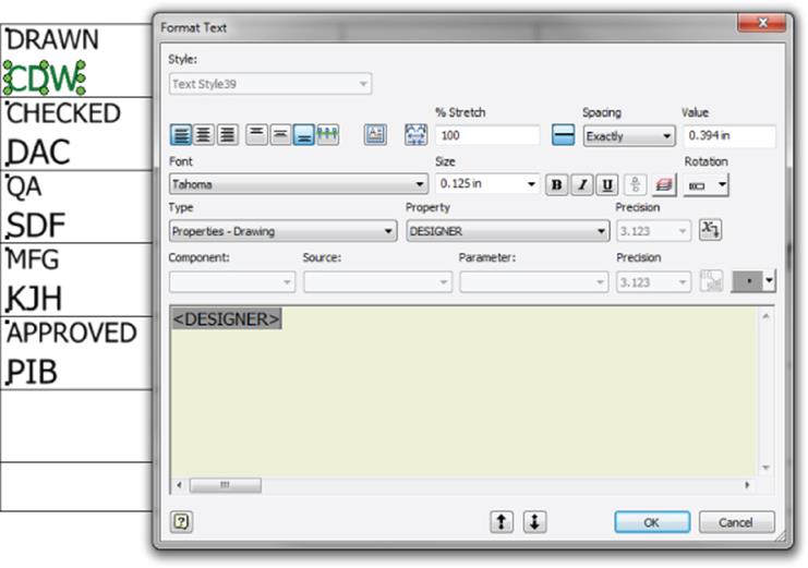
Figure 12.3 Customizing the title block
Obviously, you have not configured the entire title block at this point, but before going any further, it is important to understand where the properties you linked to the title block text fields are coming from. You can find these properties in the file iProperties. Follow these steps to change an iProperty in the drawing file and see that change show up in the title block:
1. Click the Inventor button and choose iProperties.
2. On the iProperties Project tab, change the Designer input to Test Designer.
3. Change the Creation Date input field to 1/1/2015.
4. Click the OK button to apply the changes and close the iProperties dialog box.
Your title block will have updated the two fields automatically based on the iProperty changes you made, demonstrating that you have linked those fields to the iProperties of this particular drawing file. If you intend to use this title block for your drawing template, you should continue to configure your title block to retrieve the iProperties needed, until all of the fields are automatically filled out by updating the iProperties. For now, you can close the file you have open without saving changes and continue to the next section to learn more about iProperties.
iProperties and Title Blocks
Each Inventor file has its own set of iProperties, allowing you to pull information from that file into your title block. There are two distinct methods you can use to retrieve iProperties into your title block:
· You can retrieve iProperties from the drawing file.
· You can retrieve iProperties from the model file that is referenced in the drawing file.
The following is a list of the standard iProperties available. Each of these can be accessed from the Type drop-down in the Text Format dialog box as described in the previous steps. You'll learn more about iProperties in Chapter 13, “Tools Overview.”
|
Author |
Designer |
Mfg Approved Date |
|
Authority |
Eng Approval Date |
Part Number |
|
Category |
Eng Approved By |
Project |
|
Checked By |
Engineer |
Revision Number |
|
Checked Date |
Estimated Cost |
Status |
|
Comments |
Filename |
Stock Number |
|
Company |
Filename And Path |
Subject |
|
Cost Center |
Keywords |
Title |
|
Creation Date |
Manager |
Vendor |
|
Description |
Mfg Approved By |
Weblink |
|
Design Date |
Linking Your Model and Drawing iProperties
Often, you will want the iProperties for the model file and drawing file to match. You can use the Copy Model iProperty Settings option to have this happen automatically.
To do so, open your drawing template, select the Tools tab, click Document Settings, select the Drawing tab in the dialog box that opens, and click the Copy Model iProperty Settings button at the bottom. You can have some or all of the model properties copied to the drawing.
Note that once copied, the properties do not update automatically when they are changed in the model. To update them, select the Manage tab and click Update Copied Model iProperties.
Follow these steps to modify a title block so it is pulling information from the model iProperties. You'll note that this title block is calling the model filename iProperty for the drawing title. Most of the other fields are being pulled from the drawing file's iProperties. The field you will be modifying is static and needs to be set to pull from the model file's iProperties. Here are the steps:
1. On the Get Started tab, click the Open button.
2. Browse for mi_12a_024.idw in the Chapter 12 directory of your Mastering Inventor 2015 folder.
3. Expand the sheet node in the browser (if it is not already expanded).
4. Right-click the title block instance (named MI_TB_04) in the browser and choose Edit Definition.
5. Zoom up on the title block and locate the Part Number area toward the bottom.
6. Right-click the text field showing ### and choose Edit Text.
7. In the Format Text dialog box, select the text (###) and press Delete on the keyboard.
8. Locate the Type drop-down and choose Properties–Model.
9. Set the Property drop-down to Part Number.
10.Click the Add Text Parameter button to set the property to the text field.
11.Click the OK button.
12.Right-click and choose Save Title Block (or click the Finish Sketch button on the Sketch tab).
13.Click Yes at the Save Edits prompt.
To ensure that the part number in the title block is coming from the part model and not the drawing file, you will open the model file and change its iProperties.
14.Locate the View2:Arbor_Frame.ipt node in the browser and then right-click it and choose Open.
15.Once the part model is open, right-click the top-level node (Arbor_Frame.ipt) in the browser and choose iProperties.
16.Select the Project tab and then edit the Part Number field to read 98765.
17.Click the Apply button and then the Close button.
18.Use the Open Documents tabs at the bottom of the screen to switch back to the drawing file (or use Ctrl+Tab to switch between all open documents).
You will see that the title block has read the model part number and displays the change in the Part Number field.
Experiment with the title block to understand the way it works with iProperties from the model, and then you can close the file without saving changes. You might notice that this title block does not contain dimensions. Instead, the objects within it were anchored in place using sketch constraints.
The i CHECK IT Add-in for Inventor
There are several add-ins available that check to ensure that users have not forgotten to fill out required iProperties. One such add-in is i CHECK IT from Tata Technologies. i CHECK IT goes far beyond just checking iProperties, however; it will also check to ensure that the filenaming convention has been followed, that the first sketch of a model is constrained to the origin, that all sketches are fully constrained, that only approved dimension styles are used, and much more. There are more than 100 checks that can be defined. Visit the following page to download a 30-day free trial version:
http://apps.exchange.autodesk.com/INVNTOR/Home/Index
General File Properties and Title Blocks
In addition to iProperties, you can use some other standard file properties to fill out your title block automatically. You can access them from the Type drop-down in the Text Format dialog box just as you did the iProperties. Table 12.1 lists several general properties that can be called into a text field.
Table 12.1 Available properties
|
Physical properties of the model |
General drawing properties |
Drawing sheet properties |
Sheet-metal flat pattern properties |
|
Area |
Number Of Sheets |
Sheet Number |
Flat Area |
|
Density |
Sheet Revision |
Flat Length |
|
|
Mass |
Sheet Size |
Flat Width |
|
|
Volume |
Follow these steps to set up the sheet number area of the title block to call on general file properties of the drawing file to automatically fill out the title block:
1. On the Get Started tab, click the Open button.
2. Browse for mi_12a_025.idw in the Chapter 12 directory of your Mastering Inventor 2015 folder.
3. Expand the sheet node in the browser.
4. Right-click the title block instance (named MI_TB_05) and choose Edit Definition.
5. Zoom up on the title block and locate the SHEET ?? OF ??? area at the bottom right.
6. Right-click the text field showing SHEET ?? OF ??? and choose Edit Text.
7. In the Format Text dialog box, select the two question marks between the word SHEET and the word OF and press Delete on the keyboard.
8. Locate the Type drop-down and choose Sheet Properties.
9. Set the Property drop-down to Sheet Number.
10.Click the Add Text Parameter button to set the Number Of Sheets property to the text field.
11.Still in the Format Text dialog box, select the three question marks after the word OF and press Delete on the keyboard.
12.Locate the Type drop-down and choose Drawing Properties. (Note that there is one called Properties–Drawing also, so ensure that you have the correct one.)
13.Set the Property drop-down to Number Of Sheets.
14.Click the Add Text Parameter button to set the Sheet Number property to the text field.
15.Ensure that the text in the text displays as SHEET <Sheet Number> OF <Number of sheets>. Then click the OK button.
16.Right-click and choose Save Title Block (or click the Finish Sketch button on the Sketch tab).
17.Click Yes at the Save Edits prompt.
Experiment with adding new sheets and reordering the sheets (just drag and drop the sheets in the browser) to see how the title block updates, and then you can close the file without saving changes.
Prompted Entry
You can also create fields in your title block to enter information manually using what is known as a prompted entry. Prompted entry text is keyed in by the user and not retrieved from the file properties in the way that iProperties are. Because of this, experienced Inventor users will tell you that iProperties are favored over prompted entries for two reasons.
First, information entered into a prompted entry field is stored in that one title-block instance and nowhere else. If you need to update the title block for your entire drawing library at some point in the future, you can do so easily with the Drawing Resource Transfer Wizard, which can swap out old title-block definitions with a new one, en masse. (See Chapter 13 for more on this Inventor tool.) This works well when title blocks have been populated with iProperties because the information resides in the file, not the title block. However, if a prompted entry was used, that information will not be carried over because it exists only in the old title-block instance.
Second, since iProperties are stored in the file, there are a couple of important tasks that can be performed on them:
· iProperties can be viewed, searched, and copied easily using a number of tools such as Find, Design Assistant, and Vault.
· Non-Inventor users can use iProperties to sign off on drawings without opening the file in Inventor.
Getting in the habit of using iProperties will pay large dividends in the future, once you have created many Inventor files. With these things in mind, you should use prompted entries in title blocks rarely. Here are the steps for creating a prompted entry in a title block if you determine that it is required:
1. On the Get Started tab, click the Open button.
2. Browse for mi_12a_026.idw in the Chapter 12 directory of your Mastering Inventor 2015 folder.
3. Expand the sheet node in the browser.
4. Right-click the title block instance (named MI_TB_06) and choose Edit Definition.
5. Zoom up on the title block and locate the Tracking Code area at the bottom left.
6. Right-click the text field showing ##### and choose Edit Text.
7. Locate the Type drop-down and choose Prompted Entry.
8. Replace ##### with Enter Tracking Code.
9. Click the OK button.
10.Right-click any empty space in the graphics area and choose Save Title Block.
11.Click Yes at the Save Edits prompt.
12.Enter 12345 for the tracking code, when prompted.
13.Click the OK button.
You can edit a prompted entry in a title block by expanding the block instance in the browser and double-clicking the Field Text node. If no prompted entry is established, you will only be able to view the fields. If you edit Sheet 2 and add the MI_TB_06 title block to it, you will immediately be prompted for the tracking-code entry. When you've finished exploring prompted entries, you can close the file without saving changes.
Sketched Symbols
Sketched symbols are created, edited, placed, and managed much like other drawing resources, but there is no limit to the number of sketch symbol instances you can place on a sheet. Like other drawing resource definitions, sketched symbols are placed by double-clicking the definition node in the browser or using the User Symbols button on the Symbols panel of the Annotate tab.
Sketched symbols can optionally include a leader. Using a leader, you can associate a sketch symbol with a model so that model-specific properties can be displayed in the symbol. For example, you could create a sketch symbol that calls out a component's mass:
1. On the Get Started tab, click the Open button.
2. Browse for mi_12a_030.idw in the Chapter 12 directory of your Mastering Inventor 2015 folder.
3. Expand the Drawing Resources browser folder.
4. Right-click the Sketch Symbol folder and select Define New Symbol.
5. In the Draw panel of the Sketch tab, click the Text button (or press T on the keyboard).
6. Click anywhere on the page to set the text location.
7. In the Format Text dialog box, type in a static text string that reads Mass: (be sure to include a space after the colon).
8. Locate the Type drop-down and choose Physical Properties–Model.
9. Set the Property drop-down to MASS.
10.Click the Add Text Parameter button to set the MASS property to the text field.
11.Click the OK button.
12.Right-click anywhere in the graphics area and choose the OK button.
13.Choose Save Sketched Symbol from the context menu.
14.Enter Mass for the name and click Save.
15.To insert the symbol into the drawing, right-click the Mass sketch symbol definition in the drawing browser and select Symbols.
16.Ensure that the Mass symbol is chosen from the list on the left side of the Symbols dialog box and select the Leader option.
17.Click the OK button.
18.Click any model edge in the drawing view.
19.Click again for each leader vertex you'd like and then choose Continue from the context menu.
20.Continue to place additional symbol instances, but be sure to point to a different Arbor Press component each time.
You'll notice that the symbol in Figure 12.4 has a bit more geometry than the simple symbol you just created. You can make a sketch symbol as elaborate as you like, but for the purposes of this exercise, the Mass property reference is all that is required. A finished symbol named Mass_2 has been created for you in this drawing file. If the mass shows up as N/A, it indicates that the model needs to be updated. You can open the assembly model, select the Manage tab, and click the Update Mass button to do this. Then return to the drawing to see the update.
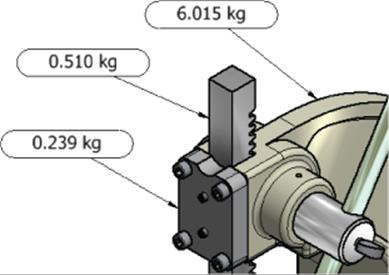
Figure 12.4 Applying sketched symbols to a drawing view
Formatting Your Text to Center Your Symbols
Generally, text objects are created with a justification setting other than middle center. However, a middle-center justification will allow you to center your text in the symbol geometry by using sketch constraints.
Here are some more sketch symbol points to remember:
· Sketched symbols are often used to create standard blocks of text notes.
· Sketched symbols can be placed as needed on new documents or placed on the template itself, which can be useful for standard drawing notes that will be placed in every drawing.
· If there is field text in the sketch symbol, it becomes populated just like title block field text when you create a new drawing.
· If you need to establish a symbol reference to a model but do not want to see the leader, you can edit the symbol and then double-click or select Edit Symbol from the symbol's context menu and uncheck the leader Visibility option.
· You cannot graphically rotate or scale static sketched symbols as you can symbols that are not static.
· Sketched symbols placed by double-clicking the definition are set to Static by default; you can set this option prior to placement if you click the User button on the Symbols panel of the Annotate tab.
· Sketched symbols placed by right-clicking the definition and choosing Symbols or by clicking the User button on the Symbols panel of the Annotate tab are set to have more controls than static symbols initially.
· You can switch a static symbol to be not static by right-clicking it and choosing Edit Symbol.
· When you mouse over a sketch symbol that is not static, a single blue hot point is shown on the center top of the symbol and four yellow hot points are displayed at the four corners of the symbol.
· Clicking and dragging the blue hot point causes the symbol to rotate, whereas clicking and dragging any of the yellow hot points enables dynamic scaling.
· You can change the insert point of a sketched symbol by adding a point to the sketch and then using the Set Insertion Point Grip button to mark it as the insertion point. This button can be found next to the Driven Dimension button on the Format panel of the Sketch tab.
· Sketched symbols can be patterned by right-clicking an instance of a symbol and choosing Pattern Symbol.
· Sketched symbols are a good place to use prompted entry text.
AutoCAD Blocks
Blocks created in AutoCAD can be used in Inventor in the same way sketched symbols are used. However, differences exist between the way they are created and used. AutoCAD blocks are available for use only when you are using an Inventor DWG file and cannot be used in an Inventor IDW file. Also, you cannot create or edit AutoCAD blocks in Inventor. There are two ways to bring blocks into an Inventor DWG file:
· Copy and paste from AutoCAD.
· Right-click the AutoCAD Blocks folder found in the Drawing Resources folder and choose Import AutoCAD.
Here are some other points to remember about blocks:
· Once blocks are imported, you can scale, rotate, and pattern them by right-clicking the block instance.
· Blocks containing attributes can be modified by right-clicking the block instance and choosing Edit Attributes.
· Color and layer properties can be modified by right-clicking the block instance and choosing Properties.
· You can create a block from your drawing views by right-clicking the browser node for the view and selecting Insert In Model Space from the context menu.
Sheet Formats
Sheet formats are preset collections of drawing sheets, borders, title blocks, sketched symbols, and/or base and projected views. They essentially give you the ability to quickly generate multiview drawings just by referencing a single model file. To create a multiview drawing, follow these steps:
1. On the Get Started tab, click the Open button.
2. Browse for mi_12a_037.idw in the Chapter 12 directory of your Mastering Inventor 2015 folder.
3. Expand the Drawing Resources browser folder.
4. Expand the Sheet Formats folder.
5. Right-click the A Size, 4 Views, 1/2 Scale format, and choose New Sheet.
6. Browse for mi_12a_038.ipt in the Chapter 12 directory of your Mastering Inventor 2015 folder and click the Open button.
7. Click the OK button in the Select Component dialog box.
You will note that a new sheet has been created to the specifications of the sheet format and set active. This technique is ideal if you find yourself detailing similar designs of common size and complexity. You can close the file without saving changes.
To save your own sheet format, set up your sheet the way you like it, right-click the active sheet node in the browser, select Create Sheet Format, and then name the sheet format as you'd like.
Here are some more sheet format points to remember:
· Only base and projected views are saved in a sheet format. Section, detail, and other such views will not be included.
· Placed drawing resources such as standard notes (in the form of sketched symbols) can be included in a sheet format.
· You can preload your drawing template as a sheet format as well. Simply open a template, create base and projected views of any model, and then save and close them. When you next use your template for a new drawing, you'll be immediately prompted to reference a model file, and the drawing views will be automatically created.
Transfer Drawing Resources
You can copy drawing resource definitions from drawing to drawing by following these steps:
1. Right-click the definition of the title block, sketched symbol, or other drawing resource you want to copy and select Copy from the context menu.
2. Right-click the appropriate drawing resource node (or the Drawing Resources folder itself in the target document).
3. Select Paste.
You can use this technique to add new drawing resources and update existing resources. You can also select the entire Drawing Resources folder in one drawing and paste it into the Drawing Resources folder of another drawing. You will be prompted to replace or make a new instance of any duplicate resources.
The copy-and-paste technique is efficient for single changes or transfers between two drawings, but to push one or more new or updated design resource definitions to multiple drawings, use the Drawing Resource Transfer Wizard discussed in Chapter 13.
Area Code Changes
In 2002, the phone number area code for Rochester, New York, and the surrounding areas changed from 716 to 585. This meant that every manufacturing, engineering, and architectural group in the area suddenly had hundreds and thousands of working drawings with the wrong phone number in the title block. Many companies that wanted or needed to update their title blocks had to manually copy and paste title blocks on each drawing in their archives (the savvier groups wrote custom application scripts to perform this task). Unfortunately, the Drawing Resource Transfer Wizard was not released until some years later. It would have likely saved thousands of hours of work.
Editing Styles and Standards
As it does with color, material, lighting, and sheet-metal styles in the modeling environment, the Drawing Manager makes heavy use of XML-based styles. The basic framework of drawing styles is no different from those in the modeling environment. Drawing style settings are viewed and edited using the Style And Standard Editor dialog box. They can be shared among a workgroup via the library that contains the modeling styles, and they can be imported and exported as stand-alone XML files.
Drawing styles differ from modeling styles more in concept than in practice, however, and the drawing styles themselves are a collection of drafting rules that include the following and many more:
· Dimension styles
· Text styles
· Balloon styles

Styles in Use, a Case Study
A standard is a collection of styles. A company called Mastering Inventor, Inc., has created a basic company standard using dimension styles, text styles, and balloon styles. The various styles' names are listed here, followed by the style category:
1. Dim_Shop: Dimension style
2. Dim_Client: Dimension style
3. Dim_Marketing: Dimension style
4. Text_125: Text style
5. Text_250: Text style
6. Text_Script: Text style
7. Text_Partslist: Text style
8. Balloon_Item_Count: Balloon style
9. Balloon_Partnumber: Balloon style
10.Balloon_Partname: Balloon style
Having these styles set up allows Mastering Inventor, Inc., to create three types of standard drawings:
· The majority of the drawings are created for use by the shop floor to make parts. These drawings are required to be clear, concise, and detailed with tolerances.
· Also required are client approval drawings, showing some design specifics but also purposely limited in detail so that a competitor cannot manufacture from them.
· Occasionally, stylized drawings for use on the company web page or at trade shows are created.
To facilitate this, Mastering Inventor, Inc., has created a separate dimension style for each of these three drawing types. The company has also created several different text styles, which are called into the dimension styles and used independently as notes, and so on. Also created were balloon styles, each set up to call different iProperties from the models. This works well because Inventor users can quickly switch to the style needed without having to stop and define a style, override another style, or worry about not maintaining consistency and/or corrupting the company standard.
The question then becomes this: If this company has three sets of styles in the company standard, how does Inventor know which one to use by default? The answer is object defaults.
To explore the use of styles, study the scenario described in the Real World Scenario entitled “Styles in Use, a Case Study,” and refer to it in the example to come.
Object Defaults
The true key to understanding how styles are used to determine the formatting of everything you can create on a drawing sheet is the notion of object defaults.
In the case-study example, it is clear that the majority of a designer's day-to-day drawing work is focused on creating prints for manufacturing. Therefore, the styles used for that type of drawing would be the styles set up as the object defaults. Object defaults are automatically set as the current styles in the template drawings. For this scenario, the object defaults would likely be configured as shown in Table 12.2.
Table 12.2 Object-default styles
|
Style type |
Object default |
|
Dimension style |
Dim_Shop |
|
Text style |
Text_125 |
|
Balloon style |
Balloon_Item_Count |
Now that you understand the overall concept of object defaults, follow these steps to see how they are managed:
1. On the Get Started tab, click the Open button.
2. Browse for mi_12a_041.idw in the Chapter 12 directory of your Mastering Inventor 2015 folder.
3. Zoom to the top of the drawing, and note the three balloons.
Each balloon on the sheet is using a different balloon style. Each balloon style is calling a different set of iProperties, as you will see by comparing the balloons to the parts list. To see how object defaults work, you'll now create more balloons on the ram part, which is the square-shaped bar with teeth cut into it.
4. Select the Annotate tab and then click the Balloon button (on the right side).
5. Note the two style drop-downs all the way to the right of the Annotate tab. The top one controls layers, and the second controls styles.
6. Click the Style drop-down to show the available balloon styles. You should see one style denoted as By Standard and three listed below that, one of which is the one called out in the By Standard line.
7. Select the Balloon_Partname style from the list and then select any edge of the ram.
8. Drag out and place the balloon on the page by clicking.
9. Right-click and choose Continue (or press Enter on the keyboard).
10.Repeat steps 6 through 9 for the other two balloon styles, until you have three balloons on the ram part, each using a different balloon style.
11.Right-click and choose Cancel when complete.
This demonstrates the use of different styles and shows that one of these styles is set as the company standard default style. You'll now go into the Style And Standard Editor and change the object default for the balloon style.
12.Select the Manage tab and then click the Styles Editor button. You will be presented with the Style And Standard Editor. (It may take a few seconds to index the styles initially.)
13.Ensure that the filter at the top right is set to Active Standard and then use the plus sign to expand the Balloon, Dimension, Object Defaults, and Text style categories, as shown in Figure 12.5. Note the style names listed under each style category.
Look at the following items:
· Company Standard (Mastering Inventor, Inc.)
· Balloon styles
· Dimension styles
· Object Defaults (Mastering Inventor, Inc.)
· Text styles
14.Click Object Defaults (MI, Inc.).
15.Locate the Balloon row in the Object Type column.
16.Click the Object Style cell for the Balloon row and set the drop-down to Balloon_Item_Count.
17.Click the Layer cell for the Balloon row and set the drop-down to Balloons.
18.Click the Save button at the top of the editor.
19.Click Done to exit the editor.
20.Select the Balloon button from the right of the Annotate tab.
21.Select any edge of the ram and place another balloon just as you did before.
22.Note that the Balloon tool now defaults to the Balloon_Item_Count style and is placed on the Balloon layer.
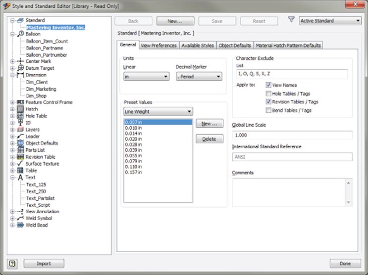
Figure 12.5 Standards, styles, and object defaults
When setting object defaults, you typically want to use the most common style. Of course, you can always use another style by manually selecting the style from the Style drop-down as you place the object. You can also select an existing object, and the Style and Layer drop-downs will display that object's style and layer, allowing you to change layer and style assignment as needed.
Objects that have been set to a specific style, rather than following the By Standard option, will not update if you make any modifications to the object defaults. However, the objects will update if the specific style is updated. A quick way to get a set of objects (like your balloons, for example) to return to their object default is to window-select or Ctrl+click the objects on the screen and then select By Standard from the style drop-down. All the objects will update to use the newly selected standard.
Set the Style Drop-Down to Last Used
You can set the Style drop-down to remember the last-used object style by selecting the Tools tab, clicking the Application Options tab, and then selecting the Drawing tab. On the right side of the Drawing tab, you will find a Default Object Style setting. If you set the drop-down to Last Used, the last-used object and dimension style is the default. For example, if you are placing dimensions on a drawing using a fractional style but the decimal style is the default, you can set the application option to Last Used so you do not need to keep changing the style back to fractional every time you access the dimension style. The Last Used setting is for the current editing session for the drawing, so if you close the file and reopen it, the Object Default will list again, until it's changed.
Creating Styles
As evident in the balloon example, you can have multiple styles for the same object type. Or you can have a single style that you always use. It's up to you to choose how many styles you have for each type, and this will be dictated largely by need. Although this section will not go through all the settings for all the styles, you will explore how to create and configure a new style as a foundation to creating all style types. Here are the steps:
1. On the Get Started tab, click the Open button.
2. Browse for mi_12a_046.idw in the Chapter 12 directory of your Mastering Inventor 2015 folder.
3. Select the Manage tab and click the Styles Editor button.
4. Ensure that the filter drop-down at the top right is set to Active Standard and then in the left pane expand the Text node to see the list of text styles.
5. Expand the Balloon node to see the list of balloon styles.
6. Click the balloon style named Balloon_Partnumber to display the style settings in the right pane.
7. Click the New button at the top of the editor dialog box and enter Balloon_Item_Qty for the style name.
8. Ensure that the Add To Standard check box is selected and click the OK button.
9. In the Balloon Style settings, under the Sub-Styles section, use the drop-down to set the text style to use the style called Text_Script.
10.Click the Shape button and select the second shape (Circular–2 Entries) from the list.
11.Below that, in the Property Display area, click the Property Chooser button.
12.Click the Part Number property in the right pane and click the Remove button to take it out of the property list for this balloon style.
13.In the Left pane, locate the ITEM and ITEM QTY properties and use the Add button to pull them into the right pane. Do this one at a time.
14.Use the Move Down and Move Up buttons to set ITEM as the top property.
15.Click the OK button.
16.Click the Save button.
17.Click the Help button in the lower-left corner of the Style And Standard Editor, and notice that this takes you to a listing and description of each setting in the balloon style. This is true of all of the style types.
18.Close the Help dialog box and click Done in the Style Editor.
19.Select the Annotate tab and click the Balloon button.
20.From the Styles drop-down on the far right of the Annotate tab, choose your new Balloon style, Balloon_Item_Qty, from the list.
21.Click the edges of parts to place on the drawing balloons that will list the item number and quantity using a script font for the text.
Although the settings for each style type vary, the steps for creating them remain consistent throughout all styles. The steps are as follows:
1. Create a new style based on an existing style.
2. Specify substyles (if applicable).
3. Configure the style settings as desired.
4. Save the new style.
Working with Substyles
A basic example of a substyle in the modeling environment is the color style, which is a substyle of the material style. Once you apply a new material to a part, not only are you changing its physical parameters, but you're also potentially changing its color so that it shows the material's color substyle. In the previous balloon style exercise, you used a text substyle called Text_Script when creating the balloon style.
The use of substyles in the Drawing Manager is extensive. Almost every kind of annotation you create in a drawing contains some kind of text (dimensions, weld symbols, and parts lists), and many make use of leaders. The text style and leader style, therefore, are frequently used as substyles of other styles. This basically provides one-stop shopping if you want to quickly change all the text on your document. If you wanted to change the font for all text, for example, you wouldn't have to go to the parts-list style and change the font, then to the dimension style and change the font, and so on; instead, you would simply change just one or two text styles that are being called into those other styles.
Substyles are coupled with their parent styles, which means a substyle cannot be purged if it's in use by another style. If you cache a high-level style into your document from the library or if you save a high-level style into the library from your file, all substyles participate in those operations.
Styles are extremely powerful formatting tools that enable you to quickly change the entire face of a document. This also serves as a warning that modifying styles without understanding how they work can quickly generate unexpected results.
Take the Time to Understand Styles
Although there's probably never been a single person who decided to use Inventor just for the “exciting” styles and standards tools, these tools are extremely powerful, and you'll be doing yourself a disservice if you don't spend some time getting to know them. They may seem complex at first, but once you understand them, they will become powerful tools. Play around with changing styles in a scratch drawing and see how the annotations change.
Another good resource for learning more about styles can be found by inserting the installation disc and clicking the Read The Documentation link on the first screen of the setup program; then click Fundamentals For The Autodesk Inventor CAD Manager under the Installation Guides category. This will open the CAD Manager Fundamentals PDF file. If you do not have the installation discs, you can find an older copy of this document included with the tutorial files in the Chapter 12 directory of the Mastering Inventor 2015 folder.
Once you have a good understanding of styles, sit down with your design group and come up with a set of standards with which everyone is happy. Apply these styles to your documents and use them for a while. One of the great aspects of the style library is that if you want to make a change, you can make it to the library, and everyone will have access to this new/changed style each time they open a file.
Drawing Style Administration
Each drawing template that comes with Inventor has a full set of styles saved (cached) in the drawing document. Although you can use the style library as a sharing and update tool, there is no direct link between objects on your sheet and styles in your library. Any in-use style is loaded into your document either automatically or manually.
If your project is set to use the style library (the Use Style Library setting is Yes or Read Only), then it's important to keep your style definitions in sync between your template file and the library. If your project is using the style library, you have a style in the library that has the same name as a style in your template, and those styles have different settings, then the definition in the library automatically overwrites the definition in the template each time it's used to start a new drawing (a warning dialog box is shown when this condition is detected).
The best way to ensure synchronization is to open your template file and run either the Update Styles tool (which pulls updates from the library) or the Save Styles To Style Library tool, depending on which way you want to transfer the styles. You can find both of these options and the Purge tool on the Manage tab.
Creating Drawing Views
You will explore the various view-creation and editing tools in the following sections, which cover how to document different types of 3D models: part, assembly, sheet metal, weldment, and iPart/iAssembly.
Drawing views reference part, assembly, or presentation files. The workflows involved in creating and editing views from these different sources are similar, but with some notable exceptions detailed in the following sections.
Green Brackets and Raster Views
The Raster View option in the Drawing View dialog box creates a static raster-based view that approximates some view features. If this check box is selected, the computation of the view is quicker, but the view is less precise. Raster views can be used to speed up the drawings of large and complex general assemblies.
Green corner brackets around the drawing view are used to denote that a view is a raster view. Additionally, raster view browser nodes are marked with a red diagonal line through the browser node icon.
You can right-click a view in the graphics area or on a view's browser node to toggle it between precise and raster view methods. You can also right-click in the graphics area and select Make All Views Precise or select Make All Views Raster to toggle all the views from one method to the other.
Creating a Base View
Creating views in an Inventor drawing is an intuitive process. You'll start by creating some basic views of a part file while exploring the procedure and options along the way. Before you create any views, first open the part to become familiar with it:
1. On the Get Started tab, click the Open button.
2. Browse for mi_12a_048.ipt in the Chapter 12 directory of your Mastering Inventor 2015 folder and click the Open button.
3. Spin the part around and take a look at it using the ViewCube® or the Orbit tool. Do not close the part.
4. On the Get Started tab, click the New button.
5. Select the Metric node from the list on the left and then choose the ANSI(mm).idw template from the Drawings section on the right.
6. On the Place Views tab, click the Base button to create a base view.
7. With the Drawing View dialog box open, move your mouse pointer around on the drawing, and you will see a dynamic preview of the part file. Do not click the screen just yet, or you will inadvertently place the drawing view.
8. Note that all open model files are listed in the File drop-down. You can select any open model file from the list or click the Browse button to select another file.
9. In the Scale input box, enter 2 or use the drop-down to select 2:1. You can specify scales in fractional or decimal formats (1/2 or 0.5 both work for half-scale).
10.Click the lightbulb button to turn on the View/Scale label.
11.In the View Identifier input, type Front.
12.In the Orientation pane on the right, click through the available options and watch the preview at your mouse pointer change. Select Top when you've finished. You'll note that although the orientation is called top, you have entered Front in the view identifier box. The orientation name can be considered a suggestion, and the word top will not show up anywhere but here.
Custom View Orientations
If the view you need to show does not exist in the Orientation pane, you can use the Change View Orientation button to step into the model and create any view orientation possible.
13.In the Style area, click just the middle button to create an unshaded view with no hidden lines. Note that the shaded button (blue) can be toggled on and off independently of the other two, but the hidden lines and no hidden lines buttons are mutually exclusive to one another.
14.Uncheck the Create Projected Views Immediately After Base View Creation check box, found in the lower-left corner.
15.Click anywhere on the page to create the view (or click the OK button).
Here are some tips for working with base views:
· Right-click any view and choose Open to open the model in a new window.
· Most of the options you see in the Drawing View dialog box can be altered later by editing the view, but it's important to set the orientation correctly originally because it cannot be changed once placed.
· To delete a view, simply hover your mouse pointer over it and then select the dotted view boundary, right-click, and choose Delete.
·
Right-click or double-click a view to edit it.
· Tangent edges and thread features that are not showing up in the view can be turned on by editing the view, selecting the Display Options tab, and selecting the respective boxes.
· Views can be moved by selecting the dotted view boundary that appears when hovering over them and dragging it into place.
· Clicking a line or lines in a view gives you control options for just those lines.
· Right-click lines, arcs, or circles and uncheck Visibility to hide those entities.
· Right-click the view and choose Show Hidden Lines to bring back lines that were hidden.
· Each base view created is listed in the browser; note the Base View button.
· Expanding the view node in the browser shows the model tree for that view where you can select all the edges of features at once. You can then right-click the selected objects on the page and toggle off the visibility, change the layer, and so on.
· To rotate a view, right-click it and choose Rotate; then select an edge to make horizontal or vertical, or use the drop-down to specify by angle.
· You can have as many base views as you need on a drawing, but the iProperties will be pulled from the first view placed.
· Views can be renamed in the browser or by editing.
· To display the view name without the scale for a single view, right-click View Label and choose Edit View Label; then remove <Scale> from the text box.
· You can suppress a view by right-clicking it and choosing Suppress.
Once you've explored the settings and edit options for the base view, you can close the file without saving changes and continue.
Set View Preferences in the Standard
You can set up view preferences for your company standard by accessing the Styles Editor, selecting Standard, and then selecting the View Preferences tab. This allows you to choose which properties to display or not display in the view label, set the First or Third Angle projection, and much more.
Creating Projected Views
Once a base view is created, you can quickly create other views based on it without having to specify the model again:
1. On the Get Started tab, click the Open button.
2. Browse for mi_12a_049.idw in the Chapter 12 directory of your Mastering Inventor 2015 folder and click the Open button.
3. Select the Projected button on the Place Views tab.
4. Click the base view.
5. As you drag your mouse pointer around the base view, notice the view previews that are being generated.
6. Drag straight to the right and click. You will see a rectangular bounding box indicating that a view will be placed there.
7. Drag straight up from the base view and click, again noting the preview.
8. Drag diagonally up and to the right from the base view and click.
9. Right-click and choose Create to generate the projected views.
10.Expand the plus sign next to the Front view in the browser to see that the projected views are listed, as shown in Figure 12.6.
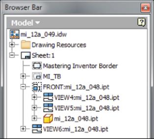
Figure 12.6 Drawing views in the browser
Here are some tips for working with projected views:
· Orthographic projected views are linked to the parent view in style and alignment and stacked below it in the browser tree.
· To break the style link between a projected view and its parent view, double-click to edit the projected view and deselect the Style From Base button in the lower right of the Drawing View dialog box. Then change the shading and hidden-line options as you like.
· Isometric views are not linked to the parent view in style and alignment and are listed separately in the browser tree.
· To break the alignment between a projected view and its parent view, right-click the projected view and choose Alignment![]() Break. A view arrow will be placed next to the parent view, and the projected view will be labeled to match.
Break. A view arrow will be placed next to the parent view, and the projected view will be labeled to match.
· To break the alignment without getting a view arrow, right-click the projected view and choose Rotate. You can set an already horizontal edge to be horizontal and still break the alignment.
· To reset the alignment, right-click the projected view and choose Alignment and then Horizontal or Vertical as appropriate. The projected view will move back into place. Choose In Position to link the projected view to the parent in its current position.
· By default, deleting a parent view or a base view will remove all projected views as well.
· To delete a parent view without removing the projected views, click the ![]() button in the Delete View dialog box, click Yes next to the views you want to keep and set them to No.
button in the Delete View dialog box, click Yes next to the views you want to keep and set them to No.
· Projected views can be created from views other than base views, such as detail views, section views, and even other projected views.
· You can select the parent view first and then issue the projected view tool, or you can issue the tool and then select the view. Either order is acceptable. If you have a view preselected accidentally and click the projected view button, that will be the view you are projecting.
· If you select the Create Projected Views Immediately After Base View Creation check box, found in the lower-left corner of the Base View creation dialog box, you can create base views and projected views at the same time.
· You can suppress a view by right-clicking it and choosing Suppress.
You can close the current file without saving changes and continue.
Moving and Copying Views
You can move drawing views between sheets by dragging and dropping the browser nodes. When a projected view is moved to a different sheet than its parent, a view arrow is generated automatically on the parent view.
To move a view, follow these steps:
1. On the Get Started tab, click the Open button.
2. Browse for mi_12a_050.idw in the Chapter 12 directory of your Mastering Inventor 2015 folder and click the Open button.
3. Expand the Front view node in the browser to show projected views 2 and 3.
4. Click the browser node of View2 and drag it down to the Sheet2 browser node.
5. Rest your mouse pointer over the top of the Sheet2 browser node icon and release the mouse button.
6. Sheet2 becomes active to show you where View2 has been moved. Notice that there is a browser icon for the Front view with an arrow and the sheet name in parentheses. This indicates it is linked to the parent view on Sheet1. Notice too that the moved view has been renamed.
7. Right-click the Front view icon in the Sheet2 browser and choose Go To to be returned to Sheet1.
8. Notice that a view arrow has been created next to the Front view.
To copy a view, follow these steps:
1. With mi_12a_050.idw still open, make sure you are on Sheet1.
2. Right-click View3 and choose Copy.
3. Right-click the browser node for Sheet2 and choose Paste.
4. Sheet2 becomes active to show you where the view has been copied to. Notice that the new view has been named with the next available view number.
Copying and moving views is often useful when you've detailed a complex view on one sheet and then have run out of space and need to expand the drawing to another sheet. Note that when you copy or move a view with dimensions or other annotations applied, the annotations are moved or copied as well. You can close the current file without saving changes and continue.
Creating Section Views
Section views are created by “sketching” a line across an existing view to define the section cut. The sketch is created automatically for you as you define the section line.
To create a section view, follow these steps:
1. On the Get Started tab, click the Open button.
2. Browse for mi_12a_051.idw in the Chapter 12 directory of your Mastering Inventor 2015 folder and click the Open button.
3. On the Place Views tab, click the Section button.
4. Click the Front view to choose it as the view to be sectioned.
5. Hold down the Ctrl key and click to the left of the view. This ensures that you do not accidentally constrain the start point of your section line to any midpoints, center points, or endpoints.
6. Release the Ctrl key, drag the line across the part, and click to the right of the part, ensuring that you see either a perpendicular or horizontal constraint to indicate you are getting a straight line.
7. Right-click and choose Continue.
8. In the Section View dialog box, note that you can change the section identifier, scale, style, and section depth. You can also create a zero-depth section called a slice. Leave all these options at the defaults.
9. Drag your cursor above the original view, and notice how the placement is constrained perpendicularly to the section line.
10.Hold down the Ctrl key and click the screen to create and place the section view anywhere you like.
11.Click the section arrow and drag it up or down to see the section update automatically.
12.To align the section view with the base view, right-click the section view and choose Alignment and then Vertical.
13.Click the base view to specify it as the view to align the section to.
14.Click the section view boundary to see how the alignment works.
Look at the browser to see how the section view was added as a child view of the base. Also, notice the sketch that was created on the base view listed just above the section view node (Figure 12.7). This sketch is the section line itself and can be edited like any other sketch. You can add or remove constraints (including sketch dimensions) as needed to precisely position the section line around your base view. You do this by right-clicking the sketch in the browser and choosing Edit Sketch, just as you would any other sketch.
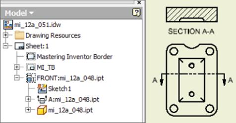
Figure 12.7 A part section view
Here are some tips for working with section views:
· Section line appearance is controlled by a layer and a style just like most other annotation objects. To determine which layer and style are used, switch to the Annotate tab and then click the section line. Note the Layer and View Annotation style in the Layer and Style drop-downs on the far right of the Annotate tab.
· Project a section view to create an isometric section.
· Orthographic section views are hatched automatically, but isometric sections are not.
· Edit or hide a hatch by right-clicking it.
· Display a hidden hatch or turn a hatch on for isometric section views by editing the view (right-click and select Edit View), selecting the Display Options tab, and selecting Hatching.
· You can hatch by material if you have mapped the materials and hatch patterns in your standard.
· Flip the section arrow direction by right-clicking the section line and choosing Reverse Direction.
· Show just the arrows of the section line by right-clicking the section line and choosing Show Entire Line.
· Edit the section depth by right-clicking the section line and choosing Edit Section Properties.
· To constrain a section line to the center of a hole, run your mouse over the hole to project the center point when you are creating the sketch line.
· When editing a section view, you click the Edit View Label button (it looks like a pencil). You can also use the Type drop-down and select View Label Properties. Then you can use the Property drop-down to add the parent sheet name or Index to your view label. This will place the parent view information in the view label for section views. This is often useful when the view resides on a different sheet.
You can close the current file without saving changes and continue.
You defined the section line on the fly during the previous exercise. Now you will bring in a sketch created in the part model and use it to create a section view. Figure 12.8 shows the sketched line in the model.
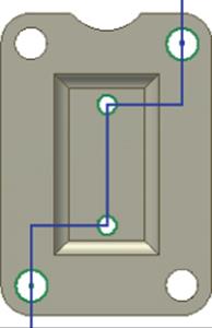
Figure 12.8 Section line sketch on model
Mapping Materials to Hatch Patterns
You can set up your template to use a predefined hatch pattern per the material of the sectioned part so that copper parts are hatched with one hatch pattern, mild steel parts are hatched with another, and so on:
1. Select the Styles And Standards panel of the Manage tab and click Styles Editor to open the Style And Standard Editor.
2. In the left pane, expand Standard and then click your standard.
3. In the right pane, click the Material Hatch Pattern Defaults tab.
4. Set the Default Hatch Style option for new materials added in the mapping.
5. Click the From File button to select a part file that contains all the material styles you want to import (set this up ahead of time), or use the From Style Library button.
6. For each imported material, click the Hatch Pattern field and select a new hatch pattern from the list. Use Ctrl or Shift to change several materials at the same time.
7. Click Save to save the changes to the current document; then click Done to close the dialog box.
To create a section from a model sketch, proceed with these steps. If you still have mi_12a_051.idw open, you can skip to step 3.
1. On the Get Started tab, click the Open button.
2. Browse for mi_12a_052.idw in the Chapter 12 directory of your Mastering Inventor 2015 folder and click the Open button.
3. Locate the sheet node in the browser and then click the plus symbol to expand it.
4. Expand the view node called Front to reveal the model.
5. Finally, expand the model node to reveal the part features.
6. On the part node (mi_12a_048.ipt), right-click and choose Get Model Sketches.
7. You will now see that a model sketch called Section Sketch:Model is present; right-click it and choose Include.
8. This will reveal a zigzag line on the part view.
9. On the Place Views tab, click the Section button.
10.Click any part of the included sketch, or click the sketch in the browser to use it as the section line.
11.In the Section View dialog box, click the Include Slice check box and then select the Slice The Whole Part check box to create a zero-depth section. Leave the other options at the defaults.
12.Drag your cursor to the right of the original view and click on-screen to create the section.
13.To change the section properties, right-click the section line and choose Edit Section Properties.
14.Deselect the Slice The Whole Part check box and the Include Slice check box to change the section to a full-depth section; then click the OK button.
15.Right-click the hatch and choose Edit; then click the Double check box.
16.Click the OK button to close the Edit Hatch Pattern dialog box.
Your section should look similar to Figure 12.9.
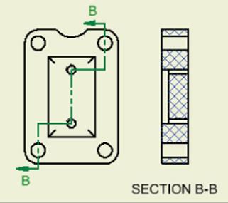
Figure 12.9 Section using model sketch
You can close the current file without saving changes and continue.
Import Hatch Patterns
You can load hatch patterns from an external PAT file to add custom hatch patterns to your drawings. To do this, edit a hatch and select Other from the Pattern list and then click Load. You can also do this in the Style And Standard Editor to add custom hatches to your company standard.
Slice Views
Slice views are simply zero-depth section views. They are often used to create cut profiles of complex surfaced parts such as automobile bodies, aircraft wings, boat hulls, and so on. A slice view is generated by creating a sketch associated with a source view and then using that sketch as the slice profile to create a slice section through a different target view. The slice is then executed on the selected target view. Slice views can be created on part views or assembly views.
To create a Slice operation defined by two existing views and sketch geometry, follow these general steps:
1. Select an existing view to use as the source view (the view you will sketch the slice onto).
2. From the Place Views tab, click the Create Sketch button.
3. Create sketch geometry to define an open profile to use for the slice.
4. Click the Finish Sketch button to exit the sketch.
5. From the Place Views tab, click the Slice button.
6. Select a view other than the view you sketched on for the target view; you'll see the Slice dialog box displayed.
7. Select the previously defined sketch profile to use as the Slice Line Geometry selection.
8. You can choose to select the Slice All Parts check box in order to override the browser component section settings and slice all parts in the view (assuming the slice sketch runs through them).
9. Click the OK button to create the Slice operation.
When working with assemblies and the slice tool, you can control which components are sliced by expanding the node for the target view in the browser and then right-clicking each component in the view model tree and choosing an option from the Section Participation flyout menu.
Using Slice Participation with Assembly Views
You can use the Slice tool to fine-tune your assembly views. However, there is a trick to getting it to work correctly.
1. Start the Slice tool.
2. Select your cutting line, but do not select the Slice All Parts check box.
3. You will be prompted with a warning: “The slice operation did not result in any sliced components….” Click the OK button in the warning dialog box.
4. In the browser, find the node for the assembly model of the sliced target view and right-click it; then choose Section Participation and select Slice. This will slice all of the parts in the assembly.
5. Then you can select individual components and change the Section Participation back to none as you see fit.
The trick here is that if you had selected the Slice All Parts option when creating the slice, you would not be allowed to control the individual section participation in the target view components.
Using Breakout Views
You can also use a breakout to show a cutaway. Unlike the Section View tool that creates a new view, a breakout is a cut operation you perform on an existing view. Breakouts start with a closed-loop profile drawn on a view sketch, so you'll begin there as well. It is important to note that in order to use a sketch for a breakout, it must be associated with the drawing view. To create an associated sketch, first select the view and then click the Create Sketch button. Clicking the Create Sketch button without selecting the view first will result in a sketch that is not associated with any view.
To create a breakout view, follow these steps:
1. On the Get Started tab, click the Open button.
2. Browse for mi_12a_067.idw in the Chapter 12 directory of your Mastering Inventor 2015 folder and click the Open button.
3. Select the view named Front View. You can determine that the view is selected by looking at the browser; it should be highlighted.
4. On the Place Views tab, click the Start Sketch button.
5. Sketch a shape similar to Figure 12.10. The results don't need to be exact, but you do need to ensure that the sketch is a closed loop.
6. Click the Finish Sketch button on the Sketch tab when your sketch is complete.
7. To ensure that the sketch has been created correctly, you can select the view on the sheet and drag it around a bit. If the sketch travels with the view, then it is associated with the view. If it stays put, it is not. You can also look at the browser and ensure that the Sketch node is stacked under Front View. If you see it above Front View, it is not associated and will not work for the breakout.
8. On the Place Views tab, click the Break Out button.
9. Select Front View.
10.Your sketch should automatically be selected as the profile, provided you have only one unconsumed sketch. Otherwise, you will select the sketch for the profile. If you cannot select the sketch, review step 3.
11.Make sure the Depth area is set to From Point and then click the center of the upper-rightmost hole.
12.Enter a depth value of 25 mm and click the OK button.
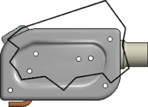
Figure 12.10 Creating a breakout sketch
Your result should look similar to Figure 12.11. Note the Break Out view node in the browser. You may be able to see some portions of the internal parts because they have been cut away as well. You'll explore how to control this in the coming pages; for now, you can close the file without saving changes.
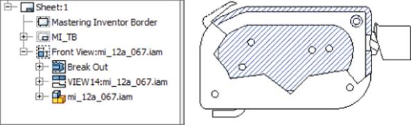
Figure 12.11 The Break Out view node and the resulting sketch
Next, you'll open a file and modify a breakout view to explore the other depth options:
1. On the Get Started tab, click the Open button.
2. Browse for mi_12a_072.idw in the Chapter 12 directory of your Mastering Inventor 2015 folder and click the Open button.
3. In the browser, right-click the Break Out node and choose Edit Break Out. You may have to expand the sheet node and the Front View node to locate it.
4. In the Depth area, set the drop-down to To Sketch.
5. Select the zigzag sketch line in the top view. Recall that you created this sketch associated with the top view by selecting the view first and then creating the view. This is required to use it as a To Sketch.
6. Click the OK button.
Examine the isometric view, and you will see that the breakout used the zigzag line as the depth extents and cut the internal and external parts. You can adjust this by going to the model tree and removing the file from section participation, as explained in the following steps.
7. Select the model node for Front View. Hover your mouse pointer over model nodes in the browser and watch the views on the sheet to make sure you are selecting the one for Front View.
8. Expand the model node to reveal all the part files and select the parts ending in 04 through 07, as shown in Figure 12.12.
9. Right-click the selected parts, choose Section Participation, and then select None.
10.The views will update on the sheet to show these parts unsectioned.
11.In the browser, right-click the Break Out node and choose Edit Break Out. Click the Section All Parts check box. This will override the Section Participation settings.
12.Change the Depth option to To Hole and click the hole/circular edge in the view named Top View.
13.Click the OK button.
14.Notice that the zigzag sketch line reappears because it is no longer used by the breakout. Also notice that the breakout depth has adjusted to stop at the center of the hole.
15.Edit the breakout once again and set the Depth drop-down to Through Part.
16.In the browser, select the parts ending in 02, 03, 08, and 09 (use the Ctrl key to select multiple parts at the same time) to ensure that they are sectioned through.
17.Click the OK button; your results should be similar to Figure 12.13.
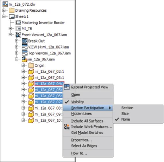
Figure 12.12 Removing parts from the breakout
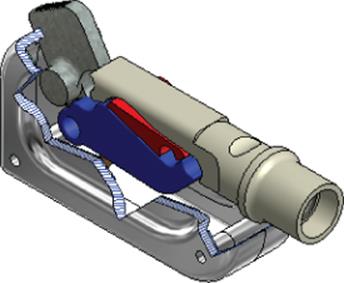
Figure 12.13 A breakout using the Through Part option
You can turn on the hatching of the sectioned parts in this view by editing the view (double-click the view or right-click and choose Edit View and then select the Display Options tab and click the Hatching check box).
Section Participation
Section participation can be controlled per the part file or per the part instance. If the part is a standard part such as a fastener, you might want to set section participation per file so the part is never sectioned. If you just want to exclude a part from a particular section or breakout view for clarity, you can do so per instance.
To control section participation per file, open the part file you want to change the section participation for, select the Tools tab, select Document Settings, and then choose the Modeling tab. Uncheck the Participate In Assembly And Drawing Sections check box. The part will now default to None in Section Participation for new section and breakout views, but it can be set to participate on a per-instance basis.
To control section participation per instance, place the section or breakout view of the assembly, expand the view node in the browser, and then locate the browser node for the parts for which you want to adjust section participation. Right-click, choose Section Participation, and set it to None as needed.
If the part was set to be sectioned in the document settings before a view was created and you change the document settings so it is not to be sectioned, the drawing view will stay sectioned and will need to be changed per instance.
It should be pointed out that the preceding steps have created a situation that may yield inconsistent results by excluding some of the parts from the section participation settings and then by setting the depth of the breakout to Through Part. Typically, you would use the section participation settings only with the first three depth options and not with the Through Part option.
You will have noticed that as you modified the breakout, the isometric view was linked to those changes. This is because isometric projected views created for views that already have a breakout inherit the breakout by default. Orthographic projected views, such as the top view, do not inherit the breakout.
To switch the inheritance setting of the isometric view, right-click it and select Edit View. In the Display Options tab in the Drawing View dialog box, deselect the Break Out check box in the Cut Inheritance area, as shown in Figure 12.14. You can also turn on hatching from this tab. You can use the current file to explore these hatch settings, and then you can close the file without saving changes.
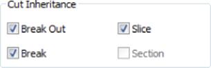
Figure 12.14 Cut Inheritance settings for isometric views
Using Detail Views
You can use the detail view to enlarge and segregate a particular portion of a drawing view as a new view. Follow these steps to explore the options of detail views:
1. On the Get Started tab, click the Open button.
2. Browse for mi_12a_077.idw in the Chapter 12 directory of your Mastering Inventor 2015 folder and click the Open button.
3. On the Place Views tab, click the Detail button.
4. Click anywhere on the Front view to use it as the basis of the new detail view.
5. In the Detail View dialog box, you can modify the View/Scale Label And Style settings just as you can in other view-creation dialog boxes. You can also set a fence and cutout shape. The Full Boundary and Connection Line options are available only if you're using the Smooth Cutout option. Figure 12.15 shows examples of the Smooth Cutout options.
6. Leave the dialog options set at the defaults and then click Front View, approximately in the center of the crescent-shaped feature, as shown in Figure 12.15.
7. Drag the boundary out to a size close to that shown in Figure 12.15.
8. Click the screen where you would like to place the detail view, and the detail is created.
9. Click the detail boundary on Front View, and note the six green grips. Click and drag any of the outer grips to resize the boundary and use the center one to control the location.
10.You can also double-click the two grips near the arrowhead and change the head style.
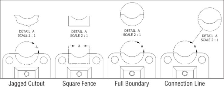
Figure 12.15 Detail view options
Here are more options for detail views:
· Right-click the detail boundary and choose Attach to anchor the detail to a specific point on the base view.
· Right-click the detail boundary and choose Options to change the detail from rough to smooth, then to add a full detail, and then to add a connection line.
· Click and drag on the detail label character (the letter A in Figure 12.15) in the boundary fence to reposition it.
· To move the detail label character out away from the boundary, right-click the detail boundary, click Leader, and then click the detail label character and drag it; it will be attached with a leader.
· Right-click or double-click the detail view to edit the view and change scale, style, detail name, and so on, as you would any other view.
· When editing a detail view, you click the Edit View Label button (it looks like a pencil). You can also use the Type drop-down and select View Label Properties. Then you can use the Property drop-down to add the Parent Sheet Name or Index to your view label. This will place the parent view information in the view label for detail views. This is often useful when the view resides on a different sheet.
Use the current file to explore these detail options and then close the file without saving changes.
Using Detail View Annotation
Although detail views are created at a scale larger than the base view, Inventor takes this into account when creating dimensions for the detail view. Therefore, all your dimensions will be to the correct scale.
Creating Break Views
Often when detailing components that are much longer proportionally than they are tall, such as frame components, it is a good idea to use the Break tool to remove portions of the model. This allows the detail of the end treatments to be the focus of the drawing. Follow these steps to explore the Break tool:
1. On the Get Started tab, click the Open button.
2. Browse for mi_12a_078.idw in the Chapter 12 directory of your Mastering Inventor 2015 folder and click the Open button.
3. On the Place Views tab, locate the Break button on the Modify panel and click it.
4. Click anywhere on the Front view.
5. In the Break dialog box, set the gap to 10 mm.
6. Click the view just to the left of where it extends past the drawing border on the left side.
7. Drag the break symbol over and click just to the right of where the view extends past the drawing border on the right side and then click on-screen.
8. Notice that the break is carried through to both views.
9. Zoom in on the break symbol and then click it.
10.Click and drag the green grip point to the left to reposition it.
11.Select the right half of the break symbol and drag it to the right and then let up. This will remove more material from the view.
12.Select the right half of the break symbol and drag it to the left and then let up. This will add more material to the view.
13.Adjust the view until it fits on the drawing sheet.
14.Click the view named Top View and choose Edit View.
15.Click the Display Options tab and uncheck the Break check box in the Cut Inheritance area. Then click the OK button. You'll notice that the view no longer inherits the break from the parent view (in this case, Front View).
16.Click the break symbol on Front View and choose Delete.
17.Right-click Sheet 2 in the browser and choose Activate.
18.Click the Break button and place the break on the view named Top View.
19.Notice the Propagate To Parent View check box. Uncheck this option to break only the view named Top View and leave the parent view from which it was created without a break.
20.Click the start point and endpoint on the view to create the break, and you'll see that the parent view is left as is.
You can continue to experiment with the Break tool and then close this file without saving changes. Here are some more points to know about break views:
· To edit an existing break, right-click the break symbol and choose Edit Break.
· The distance value entered in the Break dialog box refers to the space on the paper between the break symbols.
· You can break views vertically and horizontally using the options in the dialog box, but there is not a way to break a view at an angle when a component is not vertical or horizontal.
· There is no “pipe break” symbol for round components.
· By default, a dimension placed on the view will be broken as well, providing the break intersects it.
· You can slide the dimension break view under the dimension text to hide it on a per-instance basis.
· You can edit the dimension style and turn off the dimension break symbol option if you like. The setting is on the Display tab of the dimension style settings.
Break Symbols for Structural Detailing
If you detail plate girders and built-up members with vertical stiffeners, gussets, clip plates, and so on, you might find that the break symbol on the drawing view causes confusion. To break a view without showing the break symbol, you can configure it so that it does not show, as described here:
1. Use the slider bar in the Break dialog box to set the break symbol to the smallest scale (slide it to the far left).
2. Set the break gap to 0.0001 or some number nearing zero (Inventor will not allow a zero value).
3. Select the break symbol (it will now display as a vertical line) and then switch to the Annotate tab. Use the Layer drop-down box to place the break symbol on a nonplotting layer (you will likely need to create such a layer in your drawings).
You can try this with the file named mi_12a_078.idw; there is a layer called No Plot already created in this drawing.
Cropping Views
You can use the Crop tool on the Modify panel of the Place Views panel to crop unneeded areas of a drawing view, in much the same way a photograph is cropped. You can specify the crop boundary as part of the crop operation or create a sketch on the view first and then use it as the crop boundary. When you create a sketch to be used as a crop boundary, you must first select the view and then create the sketch, thereby associating the sketch to the view. Unassociated sketches cannot be used as a crop boundary.
The following view types cannot be cropped:
· Views containing a view break
· Views with overlays
· Views that have been suppressed
· Views that have already been cropped
For a quick reference on how to crop views, on the Get Started tab, click the Show Me Animations button. On the Show Me Animations screen, select the Drawing–Drawing Views link and then click the Crop View Animation link on the resulting screen.
Using Draft Views
Draft views are essentially just 2D sketches created in a drawing and packaged in a view “container,” allowing them to be scaled and handled like other drawing views. For instance, if you have standard details drawn in AutoCAD, you might copy them into a draft view and then place and scale them as needed.
To create standard details from Inventor views, you can use Save Copy As to create an AutoCAD DWG file and then paste the detail back into Inventor as a draft view. However, draft views have limited capabilities for sharing between drawings, so you might consider sketched symbols for standard details you plan to use over and over.
To create a draft view, follow these general steps:
1. From the Place Views tab, click the Draft button on the Create panel.
2. In the Draft View dialog box, set the label and scale and then click the Label Visibility button (it looks like a lightbulb) to display the view name and scale on the drawing.
3. Click the OK button to close the Draft View dialog box.
4. An empty view and sketch are created. Use the sketch tools to add geometry, text, and dimensions as needed, or paste in copied geometry from AutoCAD.
5. Click the Finish Sketch button to create the sketch and draft view.
Creating Overlay Views
You can create overlay views to show positional representations overlaid on top of one another, thereby communicating the change in position between the positional representations. This allows you to effectively show an assembly motion of multiple positions using a single view. To create an overlay view, the assembly must first have positional representations set up to be used. Follow these steps to explore overlay views:
1. On the Get Started tab, click the Open button.
2. Browse for mi_12a_080.idw in the Chapter 12 directory of your Mastering Inventor 2015 folder and click the Open button.
3. On the Place Views tab, click the Overlay button and select the existing view on the sheet.
4. In the Overlay View dialog box, choose Closed from the Positional Representation drop-down and then click the OK button.
The result is a view of the alternative position shown in a phantom linetype overlaid on the original. You can dimension to the overlay lines as you would any others to capture a mechanism's extension length, rotation angle, and so on. The key to overlay views is in setting up the positional representations in the assembly beforehand.
When you create the overlay, you are given the opportunity to specify a view representation for the overlay view. It's recommended that before you create an overlay view, you create a view representation that visibly isolates only the components that move as a result of the positional representation. Otherwise (as is the case in this example), all the nonmoving components are redrawn over the same components in the base view.
To change positional representations used in an overlay view, delete the existing overlay view and specify a different positional representation when placing a new overlay view. Also, be aware that because weldments are not allowed to use positional representations, overlays are not allowed for weldment drawing and will be removed if they exist when an assembly is converted to a weldment.
You can close the file without saving changes.
View Representations and Positional Representations
It's often helpful to create a view representation in your assembly and turn off the visibility for all of the parts that are not moving. Then you can use this view representation in your overlay view for added clarity.
Annotating Part Drawings
Once you've created the appropriate views to document the model, you can add annotations. You can find the annotation tools on the Annotate tab. The Annotate tab is divided into several groups of tools, including Dimension, Feature Notes, Text, Symbols, Sketch, Table, and Format tools. The following sections explore the annotation tools.
Using Centerline and Center Marks
There are four standard centerline and center mark tools as well as an automated centerline tool. These tools are called Centerline, Centerline Bisector, Center Mark, and Centered Pattern, and you can access them from the Symbols panel of the Annotate tab (look for the four buttons next to the Create Sketch button). Recall that hovering your mouse pointer over a tool button provides a tool tip with the button name and that hovering a moment longer displays a dynamic tool tip showing an illustrated example of the tool. The automated centerline tool is accessed differently than the other centerline and center mark tools, as explained in the coming pages.
Centerline
Use Centerline to draw a centerline-style line, arc, or circle by specifying points. When centerline arcs are created using circles or arcs as the selection points, a center mark is drawn on the arc along with the centerline:
1. On the Get Started tab, click the Open button.
2. Browse for mi_12a_082.idw in the Chapter 12 directory of your Mastering Inventor 2015 folder and click the Open button.
3. From the Annotate tab, select the Centerline tool.
4. On VIEW 1, click the hole at the 12 o'clock position and then the hole at 2 o'clock. Notice that the tool is drawing a straight line at this point.
5. Click the hole at 4 o'clock and notice that the centerline becomes an arc.
6. Continue around, clicking each hole, and then close the centerline by clicking 12 o'clock once again; then right-click and choose Create. Your centerline should resemble the one on the left of Figure 12.16.
7. You should still be in the Centerline tool at this point. On VIEW 4, click the center of hole A1, then B1, then B2, and finally A4.
8. Right-click and choose Create; then right-click and choose Cancel. Your centerline should resemble the one on the right of Figure 12.16.
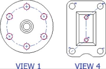
Figure 12.16 Centerlines
As you can see, the Centerline tool will triangulate the first three points and attempt to establish a centered pattern. In this way, you can use it to draw centerline arcs, circles, and lines. However, if you just need to draw a series of lines, this functionality can get in the way.
To draw just centerlines, click the first two points and then click any blank space on the sheet; then click the next two points and click a blank area again, and so on. The blank clicks are the same as right-clicking and choosing Create. Try this on VIEW 5 to draw centerlines between each of the corner holes.
Watch Your Mouse Clicks During Centerline Creation
The Centerline tool is a bit specific in the order it wants to see mouse clicks. After you have selected the final features on which to place the center mark, right-click and select Create. If you do not select Create and continue to select the next hole, you might end up with undesirable results. It takes a little getting used to, but you'll figure it out.
Centerline Bisector
Use Centerline Bisector to create a centerline halfway between two edges or two points. Note that the edges do not have to be parallel or the same length. You can even select two circles, and you will get a centerline halfway between them:
1. Still in mi_12a_082.idw, select the Centerline Bisector tool on the Annotate tab.
2. Zoom in on the center shaft area of view Section A-A.
3. Click the top and bottom lines on the shaft to create a centerline running down the middle of the section view. Notice that the distance between the two lines is bisected with a centerline.
4. Place bisector centerlines in two holes in Section A-A by clicking the opposing lines for each.
5. Right-click and choose Cancel.
6. Click the centerline you placed in the center shaft and drag out the left end so it extends past the shaft. Bisector centerlines are created based on the size of the lines you choose and may need to be adjusted. Your section view should resemble Figure 12.17.
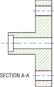
Figure 12.17 Bisecting centerlines
Center Mark
Use the Center Mark tool to annotate hole centers, circular edges, cylindrical geometry, and arcs such as filleted corners. Center marks, as well as centerlines, are primarily formatted by the Center Mark style, but there is a distinct difference between how ANSI and non-ANSI center marks are drawn, so be sure your active standard is set properly for your needs. Follow these steps to explore the Center Mark tool:
1. Continuing with mi_12a_082.idw, select the Center Mark tool on the Annotate tab.
2. Zoom in to VIEW 2.
3. Click the edge or the centers of each hole.
4. Click the outermost circle as well.
5. Right-click and choose the OK button (or Cancel).
6. Select the large center mark you just created and then click the Style drop-down box (on the Format panel of the Annotate tab).
7. Select the style called Center Mark (ISO) from the list to set the existing center mark to the ISO style. You'll notice the change in style.
Here are some Center Mark tool options to be aware of:
· For large center marks that are mostly solid lines, you can right-click them, choose Edit![]() Add/Remove Dashes, and then click the lines to place the dashes. Do the same to remove extra dashes once they are placed.
Add/Remove Dashes, and then click the lines to place the dashes. Do the same to remove extra dashes once they are placed.
· Once extra dashes have been added, click them to slide them into place.
· To lock down extra dashes, right-click and choose Edit![]() Uniform Spacing.
Uniform Spacing.
· You can align center marks with an angled edge by right-clicking them, choosing Edit![]() Align To Edge, and then selecting a diagonal edge in the view.
Align To Edge, and then selecting a diagonal edge in the view.
· You can adjust center mark overshoots by clicking the ends and dragging in or out as required.
· To reset overshoots, right-click the center mark and choose Edit![]() Fit Center Mark.
Fit Center Mark.
· To simplify center marks to just a center cross, right-click them and choose Edit![]() Extension Lines.
Extension Lines.
· You can right-click a center mark and choose Edit Center Mark Style to adjust the way center marks are drawn by default.
Centered Pattern
Use Centered Pattern to create a centerline on parts or features that have a consistent pattern. If the pattern is circular, a center mark is automatically placed:
1. Continuing with mi_12a_082.idw, select the Centered Pattern tool on the Annotate tab.
2. Zoom in to VIEW 3.
3. Click the center hole first to establish the pattern axis.
4. Click all the holes in the pattern and click the starting hole again to close the pattern.
5. Right-click and choose Create and then right-click and choose Cancel.
There are many options for creating centerlines and center marks manually, but in the next section you'll create them in a more automatic fashion. You can close the current file without saving changes and continue.
Automated Centerlines
Rather than placing centerlines and center marks manually, you can use the Automated Centerlines tool. This tool is in the context menu of each view, and you can run it on multiple views on the same sheet at one time (multiselect views while holding your Ctrl key down before executing the tool). Follow these steps to explore the Automated Centerlines tool:
1. On the Get Started tab, click the Open button.
2. Browse for mi_12a_084.idw in the Chapter 12 directory of your Mastering Inventor 2015 folder and click the Open button.
3. Hold the Ctrl key and select all four views.
4. Right-click and choose Automated Centerlines. If you do not see this option in the context menu, you have most likely selected something other than a view (such as a line or hatch pattern).
5. In the Automated Centerlines dialog box, use the Apply To buttons to select the type of objects to which you want to apply center marks and centerlines. In this case, choose all of the following:
· Hole features
· Cylindrical features
· Revolved features
· Circular patterned features
6. In the Projection area, ensure that both the Axis Normal and Axis Parallel projection buttons are selected; otherwise, the sections' views will be ignored.
7. In the Radius Threshold area, enter 3 in the Maximum box for Circular Edges. This will ensure that no center mark is placed for the outer edge of the revolved part or for the 3.94 radius circle in the hub.
8. Click the OK button and notice the centerlines and marks that have been created.
You can set the defaults for automated centerlines by selecting the Tools tab, clicking Document Settings, and selecting the Drawing tab in the dialog box that appears. Do this in your template, and you will not have to go through the process of selecting the Apply To buttons or specifying minimum and maximum threshold values each time.
Use the Undo button to reset the drawing and then experiment with the options to gain more understanding of the different features. When you have finished, you can close the file without saving changes.
Creating Dimensions
A significant portion of any detailing job is placing and modifying dimensions; therefore, it is important to become familiar with the various dimension tools and formatting options available in the Drawing Manager. Here is a quick reference of the dimension types available:
· Linear dimension from one element. For instance, select a line and drag and drop the dimension.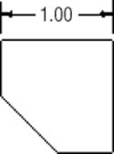
· Linear dimension between two elements. Select two endpoints, and drag and drop the dimension.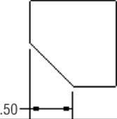
· Aligned dimension between two elements. For instance, select two endpoints of an angled line, right-click, and select Aligned to force an aligned solution.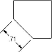
· Angular dimension between three points. Select three points; they can be endpoints, midpoints, center points, and so on.
· Angular dimension of an interior angle. Select two angular lines and drag to the minor angle.
· Angular dimension of an exterior angle. Select two angular lines and drag to the major angle.
· Angular dimension from a reference line, such as a line from an object line and a centerline or a projected work axis.
· Radius dimension. Select any circle or arc and right-click to choose either a radius or a dimension. Radius is the default for arcs.
· Diameter dimension. Select any circle or arc and right-click to choose either a radius or a dimension. Diameter is the default for circles.
· Baseline dimensions. Select objects and then set the direction and base dimensions.
· Ordinate dimensions. Select objects and then set the direction and origin dimensions.
· Chain dimensions. Select objects and then set the direction and chain dimensions.
· Implied intersection dimension. Select the first intersecting object, then right-click and choose Intersection, and finally select the second intersecting object. Next, select an object to dimension the intersection point to.
· Apply General, Ordinate, and Baseline dimensions to spline endpoints.
· Apply General and Ordinate dimensions to the X and Y Min/Max points of a spline.
Most of these dimensions can be created with just one tool, the General Dimension tool.
General Dimensions
You can find the General Dimension tool by clicking the Dimension button on the Annotate tab. This will be your primary dimensioning tool. It works very much like the Sketch Dimension tool discussed earlier in this book in that this single tool can generate several different types of dimensions depending on the geometry you select.
Once geometry is selected, you can right-click to choose the applicable options for placing the type of geometry you've selected. You can also control snap options, arrowhead options, and leader options specific to each dimension type from the context menu.
A few more types of dimensions are available in drawings than can be generated in sketches using the General Dimension tool. For instance, once an arc is selected (not a full circle), a radius dimension is created by default, but prior to placement, you can right-click and choose Diameter, Angular, Angular Foreshortened Arc Length, Arc Length Foreshortened, or Chord Length from the Dimension Type flyout, as shown in Figure 12.18.
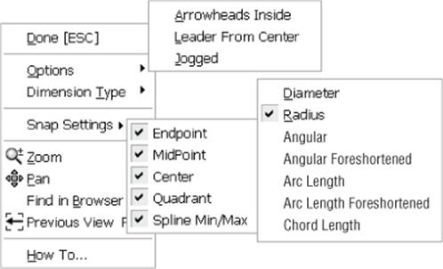
Figure 12.18 Arc dimension options
Prior to placing a linear dimension between two points or two parallel lines, you can create Linear Diameter, Linear Symmetric, or Linear Foreshortened dimensions by choosing from the dimension's context Dimension Type flyout. These types of dimensions areused commonly with symmetrical parts, especially turned cylindrical parts. Figure 12.19 shows the Linear dimension options available when two points or two parallel lines have been selected.
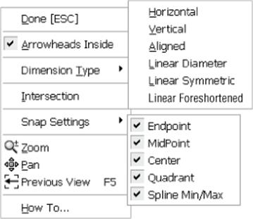
Figure 12.19 Linear dimension options
Prior to placing diameter dimensions, you can right-click and switch to a radius or change the leader options, as shown in Figure 12.20.
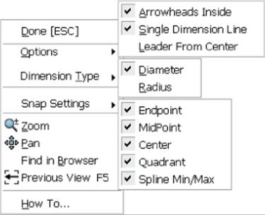
Figure 12.20 Diameter dimension options
Dimension Filters
You can create and access selection filters by holding your Shift key down and right-clicking or by clicking the selection drop-down from the Quick Access bar at the top of the screen. Selection filters specify the elements that can be selected when working in a drawing. For instance, if you choose the Detail selection filter, only objects common to detailing tasks are selectable, and items such as view boundaries, view labels, section view lines, and so on, are filtered out and cannot be selected. If you choose Select All Inventor Dimensions, you can quickly select all of the drawing dimensions and then use the Style drop-down menu to change them all to a different dimension style. You can create a custom filter also by Shift+right-clicking and choosing Edit Select Filters.
Recovering Model Dimensions
Another way to quickly add dimensions to your model views is to use the Retrieve Dimensions tool. You can access this tool from the view's context menu or from the Annotate tab. This tool allows you to recover sketch and feature dimensions that were used to model your part and bring them into the drawing view. To recover model dimensions, follow these steps:
1. On the Annotate tab, click the Retrieve button.
2. Select the view you want to retrieve dimensions for.
3. You can choose to retrieve dimensions per feature or per part, depending on what makes sense. You might choose per part when working with an assembly view, for instance. Set the radio button as you require.
4. Select the features or parts in the graphics window. You can select multiple objects by holding down the Shift or Ctrl key as you select them. Or you can window-select the whole view.
5. When selected, the part or feature will display all of the dimensions normal to the view. Click the Select Dimensions button to choose which dimensions to keep. Again, you can use a window selection to select them all.
6. Click the Apply button and then select another view to retrieve or click the OK button.
Be Warned About Model Dimensions
You should be aware that there are often dimensions required to model features that are not necessarily required or desired for use on a drawing. For example, if you were to recover model dimensions for View 7 in the file mi_12a_084.idw, you would see that the pocket is dimensioned from one end of the part and the holes are dimensioned from the other end. Not only is this poor practice, since it requires the machinist to rezero the mill, but it can also cause a tolerance stack-up.
Recovered model dimensions behave similarly to regular, placed dimensions with respect to editing and formatting. Recovered model dimensions cannot be detached or reattached from the geometry they're referencing.
Model dimension values can be directly edited from the drawing view, thus changing the model parameter value and affecting the size and shape of your model feature. Access the dimension value by selecting Edit Model Dimension from the dimension's context menu.
The ability to change model dimension values is set during Inventor installation; the default setting is to have the ability enabled. If you would prefer that users can retrieve model dimensions but not be allowed to edit them from the drawing, go through the installation configuration settings to disable this.
Exercise Caution When Editing Model Dimensions
The option to enable edits of model dimension values from the drawing can be powerful and dangerous. Editing a model dimension from a drawing is a quick way to edit the size and shape of a model, but it is often blind to other issues it may create. For example, if a part is used in an assembly and another part references holes adaptively in that assembly, changing the model dimension may affect this second part without your knowledge. It is suggested that you always open the assembly to see what else your changes will affect.
Once a particular model dimension is recovered in one view, it cannot be recovered again in any other view in the same file. You can move recovered model dimensions between views, however, provided appropriate attachment points exist in the target view. To do this, right-click the dimension and choose Move Dimension.
Baseline Dimensions and Baseline Dimension Sets
Baseline dimensions are a series of linear dimensions that terminate at a common point (or baseline). The Baseline Dimension and Baseline Dimension Set tools offer a mechanism to quickly add dimensions to a drawing view in an orderly way.
When you execute the Baseline Dimension tool, you're left with a series of conventional linear dimensions. This tool simply automates what you could do on your own with the General Dimension tool. The Baseline Dimension Set tool, however, generates a collected group of linear dimensions that are edited and moved (through dragging and editing) as a single group.
To understand this more fully, open the file mi_12a_085.idw in the Chapter 12 directory of your Mastering Inventor 2015 folder and compare the two dimensioned views. The one on the left was done with the Baseline Dimension tool, and the one on the right was done with the Baseline Dimension Set tool.
Use the views on the bottom to create baseline dimensions. Start either tool, click the left vertical part edge (this will be the baseline), and then manually select or multiselect additional features (these can be model edges or hole centers). When you've selected all the geometry you want to dimension, right-click and click to place the dimensions (shown in Figure 12.21). After you place the dimensions, you can continue to select points on the view (points on geometry rather than explicit geometry), or you can right-click and select Create.
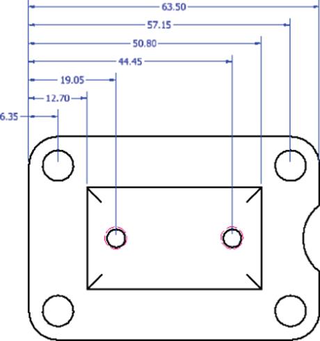
Figure 12.21 Baseline dimensions
Once a baseline set is created, you can right-click any of the dimensions and choose from the options to add a member, delete a member, detach a member, and arrange the entire set. You can also choose Make Origin to reset the base of the set. You can find the Baseline Dimension Set tool by clicking the small arrow next to the Baseline Dimension tool to reveal the drop-down list.
Chain Dimensions and Chain Dimension Sets
Chain dimensions and chain dimension sets enable you to quickly select objects and then place a chain of dimensions from point to point along the selected direction. To understand chain dimensions more fully, open the file mi_12a_092.idw in the Chapter 12 directory of your Mastering Inventor 2015 folder and compare the two dimensioned views. The one on the top left was done with the Chain Dimension tool, and the one on the top right was done with the Chain Dimension Set tool.
Use the view on the bottom left to create chain dimensions:
1. From the Dimension panel of the Annotate tab, select Chain.
2. On the drawing, select the geometry to be dimensioned by clicking to select individual edges or by clicking and dragging a window from right to left to select multiple edges.
3. Right-click and select Continue.
4. Move your cursor to preview the placement and then click to set the direction.
5. When finished, right-click and select Create.
Use the Chain Dimension tool to select the baseline dimensions in the bottom-center view to convert them to chain dimensions:
1. From the Dimension panel of the Annotate tab, select Chain.
2. On the drawing, select all of the baseline dimensions by clicking and dragging a window from right to left.
3. Right-click and select Continue.
4. Select the center marks for the two smaller holes to add additional dimensions.
5. Right-click and select Create.
Note that there appears to be a bit of a bug in the way the dimensions are arranged. To remedy this, use the Arrange button, as described here.
6. From the Dimension panel of the Annotate tab, select Arrange.
7. On the drawing, select all of the chain dimensions you just created by clicking and dragging a window from right to left.
8. Right-click and choose Contour Entity.
9. Select the edge of the part (or optionally click anywhere to the right of the part).
Use the view on the bottom right to create a chain dimension set:
1. From the Dimension panel of the Annotate tab, select Chain Set from the Chain drop-down list.
2. On the drawing, select just the top and bottom edge of the part and any one of the holes.
3. Right-click and select Continue.
4. Move your cursor to preview the placement and then click to set the direction.
5. Select an additional hole to add to the set.
6. Right-click and select Create.
7. Add more members to the set by right-clicking the set and choosing Add Member.
8. Select all of the geometry needed to complete the set so that it matches the top right view and then right-click and choose Done.
9. Right-click any of the dimensions in the set and choose Delete Member.
Once you've experimented with the chain dimension options, you can close the file without saving changes.
Ordinate Dimensions and Ordinate Dimension Sets
Ordinate dimensions and ordinate dimension sets are created much the same way as baseline and chain dimensions and dimension sets. Again, a dimension set is managed and formatted as a single, selectable object (with some exceptions), whereas the Ordinate Dimension tool results in independently controlled dimensions.
Another key difference between ordinate dimensions and an ordinate dimension set is that you can have multiple ordinate sets on a single view with different origin points. However, once you specify an origin for ordinate dimensions on a view, all ordinate dimensions placed on that view will reference that origin as well as any hole tables referencing that view. The reverse is true as well: Once an origin is specified for a hole table, ordinate dimensions on that view share the origin.
Changing Origins
You can set the origin for an ordinate dimension set after you have selected the geometry. The default origin is the first selected geometry, but you can change it. This is very powerful for updating a drawing. For ordinate dimensions, you can click the origin indicator and drag it to a different endpoint, midpoint, or center point to change the geometry reference. You can also hide the origin indicator by right-clicking it and then show it again by right-clicking any of the origin dimensions.
To understand this more fully, open the file mi_12a_099.idw in the Chapter 12 directory of your Mastering Inventor 2015 folder and compare the two dimensioned views. The one on the left was done with the Ordinate Dimension tool, and the one on the right was done with the Ordinate Dimension Set tool. Use the views on the bottom to create ordinate dimensions and ordinate dimensions sets matching the views at the top. Once they are created, explore the context menu options for the dimensions and the dimension set. You can find the Ordinate Dimension Set tool by clicking the small arrow next to the Ordinate Dimension tool to reveal the drop-down list.
Dimensions in Isometric Views
Although you may have been taught at some point that dimensions should never be placed on isometric views because traditional detailing techniques do not allow an accurate dimension to be pulled from an isometric, Inventor can overcome this by pulling the intelligence from the physical model. When you use the General Dimension tool to add dimensions to an isometric view, the resulting dimensions are fundamentally different from those you place in orthographic views.
This is immediately noticeable when you see how the resulting dimensions are drawn on the sheet: All of the dimension geometries (text, arrowheads, extension lines, and dimension lines) are drawn in 3D space and not in sheet space. Dimensions generated on isometric views are called true (meaning they reflect the true model-space dimensional value). Dimensions added to orthographic views are known as projected because the dimension value represents the calculated distance or angle between endpoints or geometry projected onto the sheet.
When placing an isometric dimension, Inventor tries to determine an appropriate annotation plane based on your geometry selection. In many cases, particularly with linear dimensions, multiple inferred annotation planes are available. Prior to placing the dimension, you can toggle through these inferred annotation planes by pressing the spacebar.
If none of the inferred work planes meets your needs, you can project the dimension either onto the sheet plane or onto a model work plane. For instance, oftentimes you will find that hole notes and leader dimensions such as radii and diameters look better placed on the sheet plane rather than in the isometric plane; therefore, you can right-click and choose Use Sheet Plane when placing them.
The change in dimension behavior (true vs. projected) happens automatically depending on the view orientation. Any projected isometric or base isometric view results in true dimensions. As a rule, newly added dimensions to a view are treated as true if none of the model's origin planes is parallel to the sheet (with the exception of auxiliary views). You can override this rule on a view-by-view basis by right-clicking a view and changing the dimension type (true or projected).
Retrieve Dimensions from Isometric Views
A quick way to place dimensions on an isometric view is to right-click the view and choose Retrieve Dimensions.
Isometric dimensions are functionally identical to orthographic dimensions; however, they cannot be “moved.” That is, they cannot be detached and reattached to different geometry, and they can't be moved using the dimension Move option on the dimension's context menu. All formatting options and behavior are otherwise identical.
Although placing isometric dimensions may seem unconventional, you can, in fact, often eliminate the number of views required to concisely communicate the design by placing dimensions on an isometric view. Try adding dimensions to the isometric view inmi_12a_105.idw, as shown in Figure 12.22.
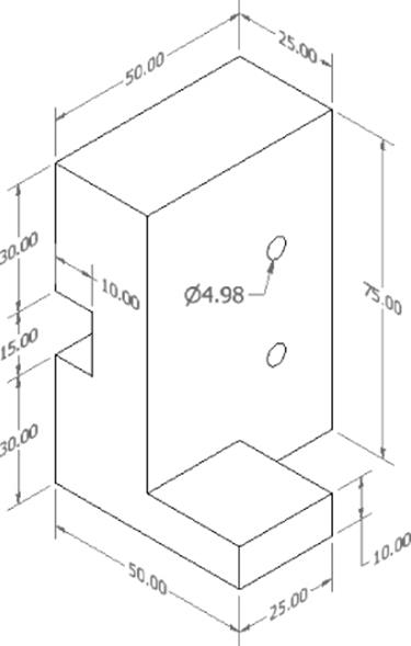
Figure 12.22 Isometric view dimensions
Formatting and Editing Dimensions
All the different types of dimensions discussed in this section are initially formatted by an associative dimension style. Indeed, each different type of dimension can be set to use a different dimension style if needed. Almost every formatting option available for dimensions is set through the dimension style. There are dozens of individual style settings—too many to list here. To learn how to change dimension formatting through styles, you'll walk through setting up a new dimension style to apply a symmetrical tolerance:
1. On the Get Started tab, click the Open button.
2. Browse for mi_12a_107.idw in the Chapter 12 directory of your Mastering Inventor 2015 folder and click the Open button.
3. On the Manage tab, click the Styles Editor button.
4. In the Style And Standard Editor, expand the Dimension node on the left side and click the Default–mm (ANSI) dimension style.
5. Click the New button along the top, thus creating a new style based on the Default–mm (ANSI) style. You can also right-click the dimension style you want to start from and choose New Style.
6. Enter PM1 for the dimension name and click the OK button.
7. Click the Tolerance tab and set the Method drop-down to Symmetric.
8. Enter 0.100 for the Upper value field and then set Linear Precision to three places, as shown in Figure 12.23.
9. Select the Units tab and change the Linear Precision setting to three places (3.123).
10.Click the Save button along the top and close the Style And Standard Editor dialog box.
11.Apply this dimension style to the existing dimensions on the sheet by first selecting them and then selecting the Annotate tab and choosing PM1 from the Style drop-down (found just under the Layer drop-down to the top right of the screen). The selected dimensions will immediately update to reflect the new style assignment.
Creating Dimension Styles
It is a good idea to create all your standard dimension styles before rolling out your style library. By creating standards for all users to use, you eliminate any discrepancy that comes from multiple users all trying to create drawings that look the same. You can create all your decimal-place dimensions (one place, two place, three place, and so on), toleranced dimensions, and even dowel-pinhole-toleranced dimension styles that users need only select.
12.Double-click the 25 mm dimension to edit it and click the Precision And Tolerance tab. The ±0.100 tolerance setting is reflected here in the Edit dialog box. Change the tolerance value to ±0.200 and then click the OK button.
You've now created two formatting overrides for the 25 mm dimension. You have overridden the standard dimension style assignment by setting it to a dimension style other than the By Standard style, and you then set a tolerance override. In addition to making style-level formatting changes to dimensions, you can copy and paste dimension formatting between dimension objects on your sheet.
13.Right-click the 25 mm dimension you just edited and select Copy Properties.
14.Click the 30 mm dimension. It will adopt both the style formatting and the local tolerance value override from your source dimension.
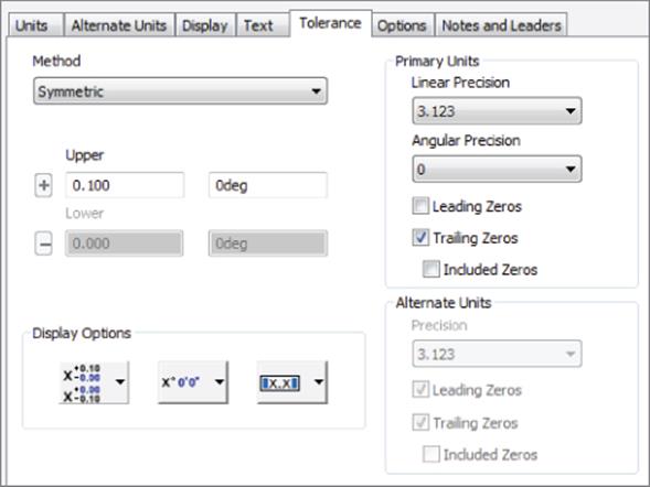
Figure 12.23 Dimension style tolerance settings
You can configure which properties are copied before selecting the target dimension by right-clicking and selecting Settings after invoking the Copy Properties tool. To edit a dimension's style, right-click the object and choose Edit Dimension Style, which will take you right into the Style Editor and highlight the dimension style. You can do this with just about any annotation object.
Hole and Thread Notes
A hole note differs from a traditional diameter dimension by calling out feature information beyond just the hole diameter. The Hole/Thread Notes command (in the Feature Notes panel) generates a leadered note that displays all pertinent hole feature information derived from the hole edge that is selected.
For example, a hole note pointing to a simple blind hole might appear as 10 × 20. A hole note pointing to a through partial-tapped hole might appear as 10–32 UNF-2B × 20.00. Inventor provides you with the ability to tailor the exact contents of the hole note through your dimension style.
Use the Hole/Thread Notes tool to add a single note for the mounting hole and tapped hole in the faceplate front view. You can configure hole notes to display whatever string of description text you prefer, as well as set the various hole parameter values' Precision and Tolerance settings. These preferences are set and stored in the dimension style.
You can configure more than 50 types of holes in this interface; they generally correspond to the different kinds of holes you can create using the Hole feature tool in part and assembly modeling (“holes” as a result of circular-extruded cuts, voids, or circular sheet-metal cut features are also supported by hole notes).
You can configure hole notes to display the hole quantity as part of the note. You can add a quantity note either directly on an individual note through the Edit Hole Note dialog box (right-click a hole note and choose Edit Hole Note) or at the style level (right-click a hole note and choose Edit Dimension style) so they appear for all holes of the same type. You can use the hole note in mi_12a_109.idw to explore this.
To add a quantity note at the style level, make sure you're editing the dimension style associated with the hole notes on your drawing (the best way to ensure this is to right-click the hole note and choose Edit Dimension Style). Select Blind - Depth Thread in the Note Format drop-down and then click in the text field so that the cursor is in front of the note text; finally, click the button with the # sign on it. This inserts the <QTYNOTE> variable token in front of the note, as shown in Figure 12.24.
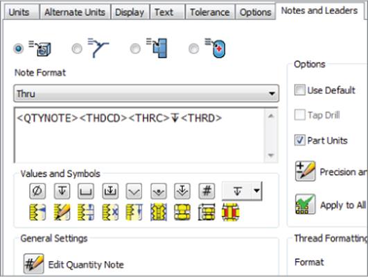
Figure 12.24 Hole note settings in dimension style
You can customize the quantity note by clicking the Edit Quantity Note button on the dimension style's Notes And Leaders tab, as shown at the bottom left of Figure 12.24. By default, the quantity note is set up as a prefix to the full hole note (2 ×). This dialog box also lets you set how the hole quantity is determined (either the number of holes in a feature or pattern or a complete evaluation of identical holes in a view where all the hole axes are normal to the view).
As soon as you save the changes to your dimension style, you should see the hole note for the tapped holes update to include the quantity of holes (2 ×).
The dimension style's Notes And Leaders tab also enables you to preconfigure other kinds of feature notes, including chamfer notes (which are actually calculated notes and not feature-dependent), punch notes, and bend notes (the latter two of which are available only for views of sheet-metal parts).
Leadered Symbols
Many of the annotations you can apply to a drawing belong to a common class of annotations often referred to as leadered symbols. These are all grouped together in the Drawing Annotation panel: Surface Texture Symbol, Welding Symbol, Feature Control Frame, Feature ID Symbol, Datum ID Symbol, and five different Datum Target tools. Each of these is created the same way, and each is formatted with its own dedicated style.
In the following steps, you will walk through an exercise that involves adding geometric dimensioning and tolerancing symbols to a drawing of a faceplate:
1. On the Get Started tab, click the Open button.
2. Browse for mi_12a_109.idw in the Chapter 12 directory of your Mastering Inventor 2015 folder and click the Open button.
3. On the Annotate tab, use the drop-down on the Symbols panel and click the Datum Identifier Symbol button.
4. Click the far-right edge of the part and drag the leader to the desired length.
5. Click the screen to set the leader and then right-click and choose Continue.
6. Accept the default A value in the text editor and click the OK button.
7. Click the bottom edge to add a second datum ID (B), but rather than placing a leader, right-click and choose Continue immediately after clicking the initial part edge point. You can do this with most Inventor leader features.
8. On the Annotate tab, use the drop-down on the Symbols panel and choose the Feature Control Frame button.
9. Rather than attaching the frame to the part, hover your mouse pointer near the bottom middle of the hole note until you see a green dot indicating the snap point (just below the N in UNF) and then click it.
10.Right-click and choose Continue to place the frame without a leader. This will attach the frame to the dimension text.
11.Fill out the appropriate fields for a positional tolerance relative to the A datum and the B datum, as shown in Figure 12.25; then click the OK button.
12.To see that the frame is attached, select the hole note and then drag the leader landing to move the note. Notice how the frame remains constrained to the hole note.
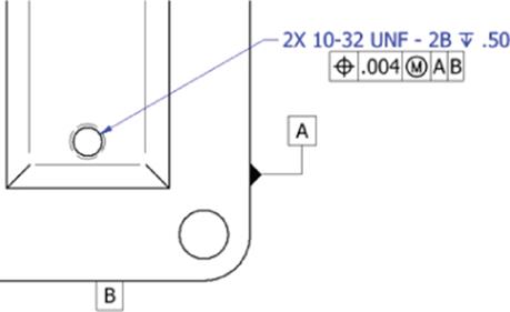
Figure 12.25 Feature control frame attached to hole note
Drawing Text
You can add text to your drawing in multiple ways. The Text tool (on the Annotate tab) is used to create general drawing notes. This kind of text is limited because it can't be associated (constrained) to a drawing view and because it offers no control over which component iProperties and parameters are being accessed when you have multiple components detailed on the same sheet.
In addition to using the Text tool, you can use the Leader Text tool (also on the Annotate tab), which can be associated to a view or a component, allowing you to extract and display iProperty and model parameter values from the component to which the leader is attached. If view associativity is required but you don't want a leader, you can right-click the leader text and choose Delete Leader.
Each of these tools utilizes the generic Format Text dialog box. This dialog box is used to edit any text-specific annotations as well as annotations such as hole tags and datum and feature IDs. The general text formatting for any drawing annotation containing text ultimately comes from a text style. Text style formatting (size, font, color, and so on) can be overwritten in the Format Text dialog box.
General Tables
You can create a table on a drawing sheet by using the General Table tool on the Annotate tab (the button is located on the Table panel and is called General). When you click the General button, you are presented with the Table dialog. You can create an empty table and then add information, or you can choose a data source from which to populate the table:
1. iParts and iAssemblies These can be used to create tabulated configuration tables. For instance, you might have an iPart bracket in six different lengths. You could select the iPart file to use as the table data source and then place a table with a row for each of the six lengths listed by their part numbers. You would choose the Length parameter to use as the column, and each row would be populated with the appropriate length value, as defined in the iPart. You can then place a view of one of the brackets and edit the dimension to read Length rather than the numeric value.
2. Sheet-Metal Parts These parts can be used to create bend tables. Selecting an existing flat pattern view as the data source allows you to choose the parameters you want to use in the bend table and then place a table indexing the bends on the flat pattern. Bend ID numbers are automatically placed on the flat pattern view. Editing the bend ID in the table updates the ID number on the flat pattern. Editing the table overrides the bend order annotation of the part file; therefore, it is typically best to use the Bend Order Annotation tool in the sheet-metal part to set the order.
3. XLS Files You can link an Excel spreadsheet file to a general table. Use the General Table tool and select the XLS file to place the table on the drawing sheet and link to the original file.
· To update the table, right-click it in the browser and choose Edit to open the XLS file. If the XLS file is linked, you can edit it outside of Inventor and right-click to choose Update to bring in the changes.
· To point the table to a different XLS file, expand the 3rd Party folder, right-click the table link, and choose Change Source. Be aware that there are limitations to the number of rows you can have using this method. Also note that blank rows in the XLS file will be read as the end of the table.
Splitting Tables
If your table has a large number of rows, it might be too long to fit on the drawing sheet. In these cases you can split the table. To do so, click the row where you want to split the table and then right-click and choose Table ![]() Split Table. You can split a table into multiple sections by using the Split Table option on a previously split table. Be sure to select the table row and not the table line before you right-click; otherwise, the Split Table option will be grayed out.
Split Table. You can split a table into multiple sections by using the Split Table option on a previously split table. Be sure to select the table row and not the table line before you right-click; otherwise, the Split Table option will be grayed out.
Once the table is split, you can drag the sections into place on the sheet as needed. In the browser you'll see the split section nested under the original table node. You can move the split table to another sheet by clicking and dragging on it in the browser and dropping it on the browser node of another sheet. To rejoin the table, you can right-click the browser node or the actual table and choose Table ![]() Un-split Table. Changes to the original table section are applied to all split sections; however, changes applied to a split section are applied to it alone.
Un-split Table. Changes to the original table section are applied to all split sections; however, changes applied to a split section are applied to it alone.
You can use the Split Table option on general tables, parts list tables, revision tables, and hole tables.
Hole Tables
You can document hole descriptions, quantities, and locations on a view by using a hole table rather than using hole notes. Indeed, you can use the hole table to document not only hole features but sheet-metal punches as well. You can even use a hole table to call out locations of recovered work points in your model. This technique can be used to detail specialized features such as slots and bosses.
Hole tables, like most types of annotation in Inventor, are initially formatted by an associative style—a Hole Table style in this case. The Hole Table style enables you to select which columns you want displayed in your table, format precision and units for the X and Y location columns, change line formatting, filter on different hole types, and configure various grouping mechanisms depending on your needs.
Everything about the hole table is formatted by the Hole Table style except for the description string for the hole. The description string uses the same configuration as your hole notes and receives this particular formatting by the hole tag's dimension style (hole tags are created with the hole table and are formatted by a dimension style).
In the following steps, you'll walk through setting up a Hole Table style and creating a hole table for the faceplate:
1. On the Get Started tab, click the Open button.
2. Browse for mi_12a_111.idw in the Chapter 12 directory of your Mastering Inventor 2015 folder and click the Open button.
3. On the Manage tab, click the Styles Editor button.
4. In the left pane of the Styles Editor, expand the hole table node, and click the style named Hole Table–mm (ANSI). The right pane will update to show the settings for this style, as shown in Figure 12.26.
5. At the top of the right pane, click the New button and set the name of the new hole table style to HT_02.
6. Click the Column Chooser button and select the Quantity property on the left of the resulting property list.
7. Click the Add button to add it to the included list of columns on the right.
8. Use the Move Up button to move the Quantity column up in the list as you like; then click the OK button.
9. Right-click the XDIM property in the Default Column Settings frame and select Format Column.
10.In the Format Column dialog box, change the precision to three places and change the column heading to X LOCATION. Note that you can format columns in this manner in almost all of the annotation tables, such as parts lists, and so on.
11.Click the OK button and repeat for the YDIM column.
12.Click the Save button to save the changes and exit the Style And Standard Editor dialog box by clicking the Done button.
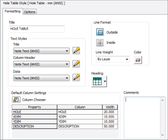
Figure 12.26 sHole Table Style dialog
You will now need to place a hole table on the drawing. Three hole table variations are available on the Table panel of the Annotate tab:
1. Selection This option allows you to select the holes you want to include in the table, and then only those holes are included.
2. View This option documents all holes in a view, although you can use filters to exclude certain hole types. As holes are added to the part, the hole table updates to include them.
3. Features This option allows you to select an instance of the types of holes you want to include in the table, and then all holes of that type are included.
To continue this exercise, you'll choose to place a hole table using the View method:
1. On the Annotate tab, select the Hole drop-down on the Table panel and choose Hole View.
2. Select the view on the sheet.
3. Next, you need to place the origin on the view. You can click any edge or vertex of the part, or you can project the edges to find the apparent intersection of the lower-left corner.
4. To place a table using the table style you created, choose HT_02 from the Style drop-down at the top right of the screen.
Finding a Corner Intersection
To find an apparent intersection for placement of an origin marker, zoom into the lower-left corner of the part. Then scrub your mouse pointer over the vertical and horizontal edges of the part and bring it to the apparent intersection; you should see the edge projected down and over and see a yellow dot at the intersection. When you do, click the dot to set the origin at that point. Be sure you run over the edges (lines) and not just the endpoints of the edges.
5. Click the screen to set the hole table on the sheet.
For each hole in the view, a hole tag is placed next to the hole edge, and a corresponding row is generated in the hole table. Also notice that because each hole is called out individually in this table, each row has a quantity of 1 (shown in Figure 12.27). You can edit the hole table by right-clicking it and choosing Edit Hole Table. From there, you can set the table to roll up all A-type holes and all B-type holes from the Options tab by selecting the Rollup radio button.
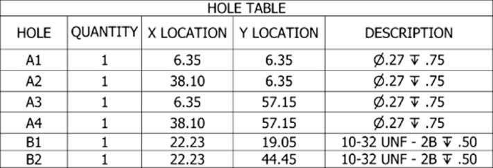
Figure 12.27 The hole table generated for the face plate
You can also edit the Tag, Note, or Description text by right-clicking the text in the table. You can make direct overrides to hole descriptions by double-clicking the description text, and you can override X and Y location precision by right-clicking an individual cell. You can access several other options by right-clicking the text in the table as well, so be certain to explore them all. When finished, you can close the file without saving changes.
Hole Tables Save Time on Large Parts
For large plates with many different holes, hole tables are wonderful. A large plate could take a half hour or more to fully dimension. Furthermore, it's often difficult for a machinist to tell where all five of the same holes are located if they are not all called out individually. The hole table gives the machinist X and Y locations of the holes that they can use to program their CNC milling machine extraordinarily quickly. Don't be surprised if the machinist asks you to dimension all your parts using hole tables.
Annotating Assembly Drawings
Creating/annotating drawing views of assemblies is similar to doing so for parts. All the same views and annotation tools discussed in the previous sections can be executed when working with assembly and presentation models. When creating views of assemblies, you will typically create parts lists and balloons and may need to control reference parts, interference edges, and assembly representations. These subjects and others dealing specifically with assembly files are covered in the following sections.
Assembly Representations
The view options available for assembly views are among the most significant differences between part and assembly model views. When an assembly file is referenced in the base view, representation options become available on the Component tab of the Drawing View dialog box. These controls allow you to specify which assembly view, positional, or level-of-detail (LOD) representation is displayed in the resulting drawing view.
View representations can optionally be made associative to the view (using the check box at the top of the View Representation control). Specifically, an associative view representation means that as a component's visibility is changed in the assembly, the change is witnessed in the drawing view as well. If the associative option is deselected, you can toggle component visibility from the drawing itself by expanding the view node in the browser, expanding the model tree on the view node, and then right-clicking a component and choosing Visibility. If the Visibility option is grayed out, the view is associative, and the component visibility is being controlled in the assembly.
Making Your Views Associative
Most of the time you will want to make your views associative. If you do not, you'll be scratching your head trying to figure out why the drawing view is not matching your view representation.
Recall the general definitions of each assembly representation type:
1. View Representations These control component visibility, color overrides, and parts list filters.
2. Positional Representations These show an assembly in different physical positions.
3. Level-of-Detail Representations These control visibility and manage memory consumption by suppressing components.
In the next several steps, you will edit a view of an assembly to see how to use assembly representations in drawing views:
1. On the Get Started tab, click the Open button.
2. Browse for mi_12a_115.idw in the Chapter 12 directory of your Mastering Inventor 2015 folder and click the Open button.
3. In the browser, expand the Sheet1 node to reveal the node for each existing view.
4. Expand the Main View node to reveal the assembly node and then expand the assembly node to reveal the parts tree.
5. Right-click the view called Main View and choose Edit View to examine the view options dealing with representations. Notice the different representations, as shown in Figure 12.28.
6. In the View area, choose the view representation named Frame And Ram and then click the OK button.
You'll notice that all of the parts are gone now except the frame and ram. This was set up in the assembly by toggling the visibility state off for all the other parts and then saving the view configuration as a view representation. Examining the browser, you'll see that the parts set to not be visible are grayed out.
7. Right-click the view called Main View and choose Edit View again.
8. In the Level Of Detail area, choose the representation named Handle And Ram and then click the OK button.
You'll note that only the ram remains on-screen. This is because you have the view set to use two different representations at once. In the view representation, the visibility is turned off for everything but the frame and ram, but the frame was suppressed in the level of detail. Examining the browser, you'll see that suppressed parts are not listed.
Typically, it's best not to use these two representations together because it can be confusing as to what is being controlled where. However, there are times when this is the best way to achieve the desired results.
9. Right-click the view called Main View and choose Edit View once again.
10.Set the view representation to Master and set the positional representation to Closed (leave the LOD as is); then click the OK button.
You'll see that now just the handle, shaft, and ram parts are shown (because of the LOD representation), and the positional representation is controlling the positions of these parts.
11.Right-click the view called Main View and choose Edit View once more.
12.Set the view representation to Default and click the Associative check box button (it looks like a chain link).
13.Set the LOD representation to Master and then click the OK button.
14.In the browser, right-click the Arbor Frame node and notice that the Visibility option is grayed out.
15.Right-click the Main View node and choose Edit View one more time.
16.Uncheck the Associative check box button and then click the OK button.
17.In the browser, right-click the Arbor Frame node and notice that the Visibility option is now available.
18.Click Visibility to toggle it off and notice that the frame is removed from the view.
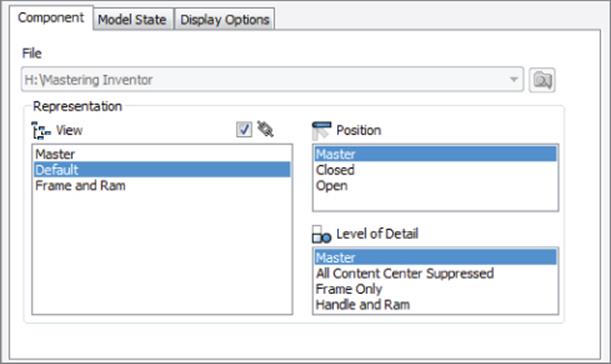
Figure 12.28 Assembly base view creation
You are now controlling component visibility at the drawing level rather than using the assembly view representation's visibility controls. You can continue experimenting with the representation options and then close the file without saving changes.
Open Assembly Drawings With The Fast Open Option
When you select a drawing file to open in the Open dialog box, you can then click the Options button and select the Fast Open option to open the drawing quickly. When the Fast Open option is selected, Inventor skips all of the model file references, making no attempt to find the referenced files. Once the drawing is open, the drawing behavior is that of a drawing that had been opened with no file references found. You can make changes to the drawing such as text notes, and so on, and then save the changes.
If you'd like to make the file references live once it is open, you can click the top-level node in the browser and choose Resolve File.
Reference Data in Drawing Views
Assembly components can be designated as Reference. You can apply this attribute as a document setting on the part or assembly file itself or on a per-instance basis when it's placed in a higher-level assembly. In addition to being omitted from the assembly mass property calculations, BOM, and subsequent drawing-parts lists, reference components are drawn and calculated differently in assembly drawing views.
By default, all reference component edges are mapped to a unique layer with a broken line style (double-dash chain). Hidden-line calculation, by default, is run separately for reference components and nonreference components. Finally, reference components do not affect the calculation of the drawing boundary. This means that if you have a reference component well apart from nonreference parts in an assembly, it may not be visible in a drawing view until you increase the reference margin.
To explore these settings, you can open the file mi_12a_117.idw in the Chapter 12 directory of your Mastering Inventor 2015 folder and compare the two views. The view on the left shows the reference part at the default settings. The view on the right has been adjusted to show the reference part as a standard part. Right-click the view and choose Edit to adjust all the reference data view behaviors on the Model State tab of the Drawing View dialog box. Figure 12.29 shows the default settings.
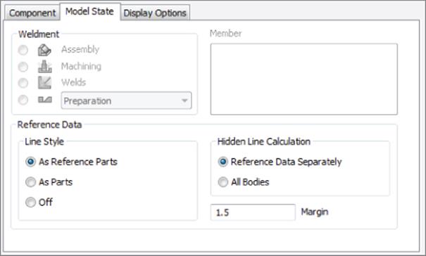
Figure 12.29 Reference data settings
Interference and Tangent Edge Display
As you place and constrain components in an assembly file, it may be necessary to create an interference condition between parts. This is common for press-fit conditions such as pins in undersized holes. This condition is common in Inventor even when you have a threaded fastener being inserted into an equal-diameter threaded hole. These edges are designated as interference edges and can be turned on or off as needed.
You can also control the display of tangent edges for cylindrical faces, fillet edges, and so on, in your drawing views. Both tangent and interference edges can be enabled by editing the view and selecting the Interference Edge check box on the Display Options tab.
Figure 12.30 shows the difference between two views with these edges turned off and turned on. The interference edge in this case is the small set screw in the middle of the plate. All other differences are tangent edges.
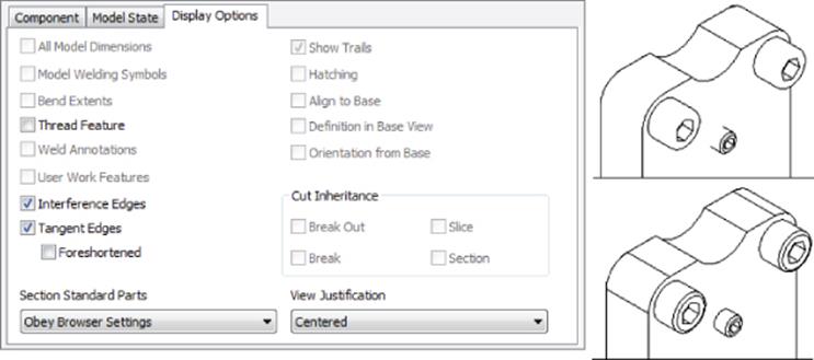
Figure 12.30 Tangent and Interference edges
Parts Lists
A parts list is a formatted report of the assembly bill of materials placed on the drawing in a table. Most of the data you see in a parts list comes ultimately from the assembly BOM, but the BOM and the parts list are managed separately inside Inventor, providing control and flexibility for managing both.
Parts lists have a dedicated formatting style that provides dozens of formatting variations. You'll walk through a typical parts-list editing and creation workflow to see what kind of capabilities can be leveraged in the parts lists:
1. On the Get Started tab, click the Open button.
2. Browse for mi_12a_119.idw in the Chapter 12 directory of your Mastering Inventor 2015 folder and click the Open button.
3. On the Manage tab, click the Styles Editor button, expand the Parts List node, and click the style named MI_PL_02.
4. Click the Column Chooser button and add the Material property from the list on the left. Then click the OK button.
5. Click the Heading button and change the placement to Bottom.
6. Save your changes and exit the Style And Standard Editor dialog box using the Done button.
7. On the Annotate tab, click the Parts List button.
The Parts List dialog box allows you to either click an assembly or presentation drawing view or browse directly to an assembly or presentation file (you can create a parts list on a drawing with no drawing views). You can choose either a structured (first or all levels) or parts-only parts list. If the parts list is too long for the sheet size you're placing it on, you can also enable the option to wrap the parts list based on a specified number of rows.
8. Click the view on the sheet, and ensure that Structured is selected for the BOM view type and the Direction To Wrap Table option is set to Right. Click the OK button and then snap the parts lists to the lower-left corner of the drawing border.
Although you can specify the default column width at the style level, you may need to adjust the width based on the length of the text strings read in from the component iProperties. You can adjust column width by clicking and dragging the vertical column lines on the parts list on your sheet.
9. Resize the Material column on the parts list to better accommodate the long description text.
The initial item numbering for the components and the row order come from the last saved state of the assembly BOM but can be changed by editing the parts list.
10.Double-click the parts list to launch the Parts List dialog box (or right-click and choose Edit).
11.Click the Sort button, sort by part number in descending order, and then click the OK button.
12.Click the Renumber Items button and notice how new item numbers are assigned based on the sort order.
The new item numbers appear blue and bold in the Parts List dialog box to indicate that they do not match the BOM. Changes you make to any of the cells in the Parts List dialog box (except for custom rows or custom columns) are treated as overrides to the BOM data. However, only item number overrides can be written back to the BOM. All other overrides are preserved at the parts-list level, allowing for greater flexibility of parts-list edits at the drawing level without worries that they will be discarded if updated in the BOM. Item number changes can be saved to the assembly BOM cell by cell from the context menu or for the entire parts list in one of three ways:
· While editing the parts list, click the Save Item Overrides To BOM button along the top.
· Right-click the parts list itself on the sheet and choose Save Item Overrides To BOM.
· Right-click the Parts List browser node and choose Save Item Overrides To BOM.
If you intend for the overrides of properties other than the item numbers to match in both the BOM and parts list, you should make those edits in the BOM, where they will push through to the parts list. You can access the BOM quickly by right-clicking the parts list and choosing Bill Of Materials. Edits made in the BOM editor are written back to component iProperties and, therefore, push through to the parts list, provided no parts list overrides have already been made.
13.Click the OK button to apply the changes and exit the Parts List dialog box.
14.Right-click the drawing view and choose Edit View.
15.Set the view representation to Frame And Ram and then click the OK button.
Notice that the parts list still displays the full assembly even though the view now shows only the frame and ram parts. To set the two to coincide, you will apply a parts list filter.
16.Edit the parts list and click the Filter button, found along the top of the Parts List dialog box.
17.From the Define Filter Item drop-down box, select Assembly View Representation.
18.Choose Frame And Ram from the drop-down box and then click the green check mark. Then click the OK button to apply the filter.
19.Click the OK button in the Parts List dialog box.
You'll see the parts list update to show only the parts corresponding to the view representation. The parts list is not directly associated with any drawing view (if you choose a view when you create the parts list, it acts only as a pointer to the assembly file itself). You can close the file without saving changes. In the next section, you'll explore balloons.
Autosort and Update Parts Lists
When sorting a parts list, you can use the Autosort And Update option to maintain the sort order even when future parts are added to the assembly file.
Balloons
Assembly drawing views are related to parts lists by ballooning the components in the assembly drawing view. Balloons are perhaps the only type of annotation relevant for assembly views only. By default, balloons are set to display just a component's assigned item number, but through changes to the balloon style, a balloon can be configured to display any component iProperty or BOM property. Review the creation and editing of balloon styles in “Editing Styles and Standards” earlier in this chapter.
You should know that only items visible in a view can be selected for placing a balloon; however, you can string multiple balloons together on a single leader, including parts that are not visible, virtual parts, and even line items added to the parts list that do not exist in the assembly BOM. This is also a common technique when ballooning a collection of hardware such as a screw, lock washer, and split washer.
Follow these steps to explore methods and options for balloon placement:
1. On the Get Started tab, click the Open button.
2. Browse for mi_12a_120.idw in the Chapter 12 directory of your Mastering Inventor 2015 folder and click the Open button.
3. On the Annotate tab, click the Balloon button. Select the cap on the end of the handle, drag out and click to place the balloon on the sheet, right-click and choose Continue, and then right-click again and choose Cancel.
4. Right-click the balloon and select Attach Balloon.
5. Click the lever arm. The balloon for the lever arm is shown attached to the handle cap's balloon (Figure 12.31). Drag your mouse pointer around the balloon to set the position of the attached balloon and then click to place it.
6. Right-click the balloon and select Attach Balloon From List.
7. Select the box next to Spare Cap and click the OK button. The spare cap is a virtual component created in the assembly BOM.
Balloons can be added one at a time, or you can use the Auto Balloon tool (under the Balloon flyout) to quickly add multiple balloons to a drawing view.
8. Click the drop-down on the Balloon button and select Auto Balloon.
9. Select the view on the sheet and then window-select all the components in the view.
10.Click the Select Placement button and change the placement options. Move your mouse pointer around the sheet to see how the preview graphics update.
11.Set the placement option to Horizontal, place the balloons above the assembly, and then click the OK button.
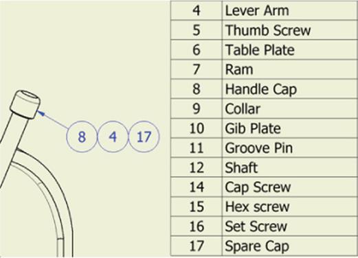
Figure 12.31 Attached balloons
Here are some tips for working with balloons:
· Click a balloon to reposition it on-screen.
· Click the leader and drag it off the part edge and onto a part face if using the edge does not make clear what part is being specified.
· Be aware that items are not updated in balloon contents when they're not attached to an edge, so if you pull a balloon from the edge of item 1 and place it on the face of item 2, the balloon will still read item 1.
· You can reassociate balloons from one part to another part by dragging the arrowhead from one part edge to the edge of a different part.
· Balloons not attached to an edge use an alternative leader style (most often a dot). You can specify a different alternative leader style in the balloon style.
· If you right-click a balloon and choose Edit Balloon or double-click anywhere on the balloon, you can change the item number and have it update the part list. Or, you can type in an override, and it will not update the parts list.
· If you right-click a balloon leader, you can choose Attach Text To Leader and add text along the leader line.
Explore the balloon options and then close the file without saving changes.
Center of Gravity Display
You can display the center of gravity (COG) of a part or assembly in a drawing view as a center mark. Only one COG can be shown per view, with the exception of overlay views. Using a drawing containing an overlay view, you will take a look at displaying the COG marker in a drawing to show the change in the COG between the two overlaid positional representations:
1. On the Get Started tab, click the Open button.
2. Browse for mi_12a_123.idw in the Chapter 12 directory of your Mastering Inventor 2015 folder and click the Open button.
3. Expand the sheet node in the browser and locate the Base View node and expand it.
4. Right-click the mi_12a_115 assembly icon and select Center Of Gravity.
Doing so recalculates the model's center of gravity (it does not read the value in from the model's physical properties) and draws a center mark at the calculated location.
5. Locate the overlay node in the browser and expand it.
6. Right-click the mi_12a_115 assembly icon listed in the overlay tree and select Center Of Gravity.
7. Finally, dimension the location of these center marks relative to the bottom-right corner of the Arbor Press frame.
8. Double-click to edit one of these dimensions and add (COG) as a suffix to the dimension value on the Text tab of the Edit Dimension dialog box.
9. Right-click the dimension and use the Copy Properties option to copy this appended text to the other COG dimensions, as shown in Figure 12.32.
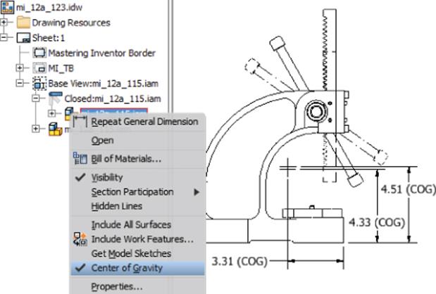
Figure 12.32 Overlay view with recovered COG
Working with Sheet-Metal Drawings
Drawing views of sheet-metal parts offer some unique options beyond those normally available for conventional part files. Among these are the inclusion of bend notes, bend lines, punch notes, bend tables, and the creation of flat pattern views.
Flat Pattern Views
When a sheet-metal part file has a flat pattern definition, you can create a drawing view of the folded model or the flat pattern. You can include both as well, but you need to separate base views to do so. To take a look at these options, follow these steps to create a flat pattern drawing view to start off:
1. On the Get Started tab, click the Open button.
2. Browse for mi_12a_130.idw in the Chapter 12 directory of your Mastering Inventor 2015 folder and click the Open button.
3. Right-click the existing isometric view and choose Open to open the model file.
4. Take a look at the model and note that this file has been created using the sheet-metal tools discussed in Chapter 6, “Sheet Metal,” and that a flat pattern has been generated in the model.
5. Use the file tabs at the bottom of the screen to switch back to the drawing file (or press Ctrl+Tab).
6. On the Place Views tab, click the Base View button.
7. Ensure that the component listed in the File drop-down is mi_12a_130.ipt.
8. On the Component tab in the Drawing View dialog box, select the Flat Pattern option as well as the Recover Punch Center option, set the scale to fit that sheet, and then place the view of the flat pattern on the sheet.
Leave this file open because you will use it in the following pages.
Bend Centerlines and Extents
Bend centerlines are drawn on sheet-metal flat pattern views where the center of the bend is located on the material face. Inventor tracks negative and positive bend centerlines independently of one another to enable users to apply different line formatting for these two conditions. This has already been done in mi_12a_130.idw, but it should be noted that the default behavior is to have both positive and negative bend lines placed on the same layer. If you want to separate them, simply create a new layer called Bend Centerline (negative); then under Object Defaults in the Styles And Standards Editor, assign Sheet Metal Bend Centerline (+) and (−) to the appropriate layers.
Lines representing bend extents can be enabled by right-clicking the flat pattern view, choosing Edit View, selecting the Display Options tab, and selecting the Bend Extents option.
Bend and Punch Notes
You'll find two sheet-metal-specific annotation tools on the Annotate tab: Bend Notes and Punch Notes.
Bend notes are placed on bend centerlines in sheet-metal flat pattern views and can convey information about the bending operation, including the bend radius, direction, angle, and K-factor. To place bend and punch notes, continue working with the mi_12a_130.idwfile or open this file and activate Sheet2 to pick up from this point:
1. Click the Bend button on the Feature Notes panel of the Annotate tab.
2. Click one of the bend centerlines in the drawing view to place a single note.
3. To place the rest of the bend notes, window-select the entire view. This tool looks only for bend centerlines, so you needn't be concerned about unintentionally selecting regular model edges.
By default, the bend notes are drawn adjacent to the bend centerlines, but where the note may be obscured in the view, you can drag individual bend notes to flip them to the opposite side of the bend centerline, or you can drag away from the bend centerline, and a leader will be generated back to the bend centerline. Try this with the two outermost bend notes on the electrical-box flat pattern view (shown in Figure 12.33).
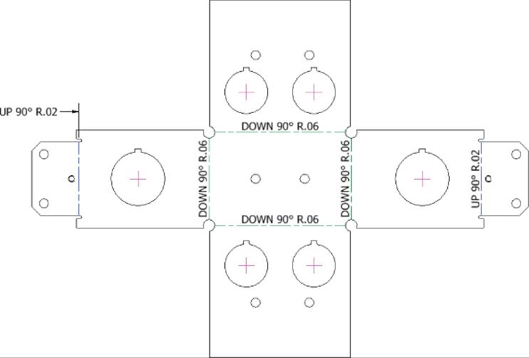
Figure 12.33 Bend notes in flat pattern view
The style formatting and direct editing of bend notes is identical to formatting and editing hole notes. You can preconfigure the contents of the note with the note's dimension style by adding one or more variable tokens for the bend note attributes. Punch notes are used to convey information about sheet-metal punch features (a special kind of iFeature). Punch notes can be applied only to flat pattern views of sheet-metal parts. They can be attached to recovered punch centers (shown as center marks in the flat pattern drawing) or on any model edge generated by the punch.
Punch notes can be configured to display the punch identifier (defined as part of the iFeature definition), the punch angle, the depth, and the direction. Punch notes are likewise formatted through dimension styles and have a similar editing interface to hole notes.
Bend Tables
Bend information can alternatively be displayed in a table rather than a note. A bend table is generated using the General button on the Table panel on the Annotate tab. The Table tool basically morphs into several different kinds of tables depending on what you specify as a data source. If a flat pattern view is selected, a bend table will be generated.
To create a bend table for mi_12a_130.idw, activate Sheet3 and then follow these steps:
General Tables
If no data source is selected in the Table dialog box, you'll end up with an empty table that you can populate manually. You can also browse and import data from a CSV or XLS file into the table.
1. Click the General button on the Table panel of the Annotate tab.
2. Select the flat pattern view.
3. Click the Column Chooser button and select Bend Radius from the list on the right.
4. Click the Remove button and then click the OK button.
5. For Bend ID, select the Alpha option and then click the OK button.
6. Place the table on the sheet and adjust the bend ID tags as required by clicking them and dragging.
A bend table is edited and maintained like a parts list. The Table dialog box is essentially identical, and any changes to the cell data are treated as overrides to the data source (in this case, the bend data stored in the sheet-metal file). You can close the file without saving changes. Figure 12.34 shows a simple bend table and bend ID tags.
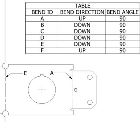
Figure 12.34 Bend table
Punch Tables
Punch information can likewise be displayed in a table, but because punches closely resemble holes with respect to the kind of information required to be displayed, a hole table is used to generate tabulated punch data. The only difference between creating a hole table and creating a punch table is that you use a predefined hole table style that is set to pick up only sheet-metal punch features. Here are the general steps used to create a punch table:
1. Ensure that your flat pattern view has been set to collect punch centers. (Right-click and select Edit View![]() Recover Punch Centers.)
Recover Punch Centers.)
2. Start the Hole Table–View tool (using the Hole View button found on the Table panel of the Annotate tab).
3. Select the flat pattern view.
4. Select an origin point.
5. Prior to placing the table, change the table's style to a punch table style. If you forget this step, you can always select the existing hole table and change it to the punch table style using the Style drop-down (top right of the screen).
Figure 12.35 shows a simple punch table.
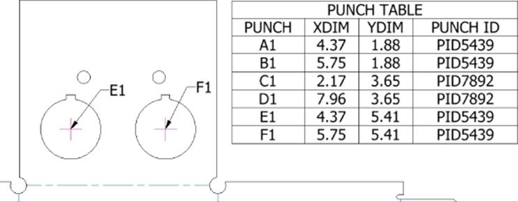
Figure 12.35 Punch table
Working with Weldment Views
Weldments are a special kind of assembly model and offer unique drawing view and annotation options in the Drawing Manager. Here, you'll take a quick look at the way drawing views handle weldment stages for detailing. For more information on working with weldments and weldment annotation, refer to Chapter 10, “Weldment Design.” A drawing view of a weldment assembly can display any of the weldment states, which are as follows:
1. Assembly Displays the base assembly prior to the preparation, welding, and machining stages.
2. Machining Displays assembly features that represent the post-weld machining and finishing.
3. Welds Displays the assembly as it exists during the weld stage, before machining but after preparations have been made. Weld beads are also shown.
4. Preparations Displays assembly features such as chamfers, extrude cuts, and holes used to remove material to prepare the assembly for welding. You can set the view to display the entire assembly during the preparation stage or set the view to look at a single component as it exists at the preparation stage.
Follow these steps to explore the way weldments are handled in drawings and drawing views:
1. On the Get Started tab, click the Open button.
2. Browse for mi_12a_139.idw in the Chapter 12 directory of your Mastering Inventor 2015 folder and click the Open button.
3. Notice the following about the views on this drawing sheet:
· View-1 through View-4 show the assembly with no preparations, welds, or machining.
· View-P1 through View-P3 show each part at the preparation stage.
· View-W1 shows the weldment with welds but no machining done after the weld stage.
4. Right-click View-1 and choose Edit View; then click the Model State tab in the Drawing View dialog box.
5. Currently, this view and the views projected from it are set to the assembly state. Select the Machining option, as shown in Figure 12.36, so the view displays the completed weldment. Click the OK button.
6. Notice that View-1 through View-4 now show the weldment at its completion, including the machined holes that run through the weld on one side (see Detail A).
7. Edit View-W1 and check the Model State tab to see that it is set to the Welds option.
8. Click the Display Options tab and select the options to recover weld annotations and model weld symbols. Then click the OK button.
9. Because the weldment included the weld symbols, they can be pulled into the drawing. Click each symbol and use the grip snaps to arrange them as you like.
You'll also notice a series of arcs indicating the weld bead brought in via the Weld Annotations option. You can right-click those and choose Edit Caterpillar to adjust the appearance of each, or you can turn the visibility off as required. Figure 12.37 shows the view with recovered weld annotation and symbols.
10.Edit View-P1 through View-P3 to check the Model State tab settings for these views. Notice that each of these views is actually created from the assembly file but is set to look at the individual parts at their preparations stage.
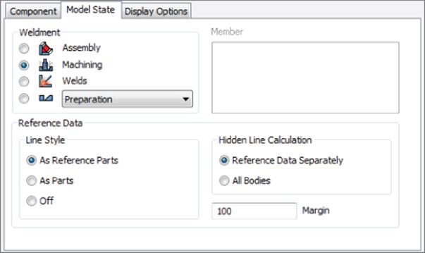
Figure 12.36 Weldment state settings
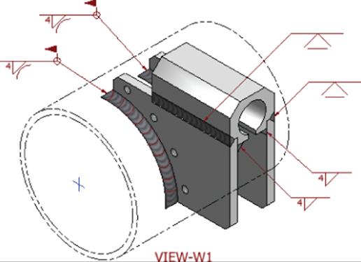
Figure 12.37 Weldment drawing with recovered annotation and weld symbols
You might also note that the balloons on View-P1 through View-P3 are calling out the filenames and that both of the side plates are the same file but have opposing chamfers. This is because a common plate was used for both sides and then prepared as required in the weldment assembly. If you were to make views of the parts themselves instead of each part at the weldment preparation stage, the chamfers would not be present. You can close this file without saving changes.
If you don't need to use the weldment tools in assembly modeling but still need to convey welding information in a drawing, you can create weld symbols and weld annotations (end fills and caterpillars) manually on the drawing view. Each is available in the Symbols panel of the Annotate tab (as shown in Figure 12.38) and is formatted by a dedicated style (the Weld Symbol style and Weld Bead style, respectively).
Figure 12.38 Weldment annotation and weld symbols can be created in the drawing
Working with iParts and iAssembly Drawings
When your drawing view references an iPart or iAssembly, you can choose, from the drawing view Model State tab, which member file you want to document.
Annotations (particularly dimensions) attached to drawing views of iParts and iAssemblies generally remain attached if you edit the base view and change the iPart member on the Model State tab. This means you can fully annotate just one iPart or iAssembly member and select Save Copy As for each unique member after changing the member referenced in the base view. Or you can create a tabulated drawing detailing all of the iPart/iAssembly members on a single sheet. To look at this workflow, follow these steps:
1. On the Get Started tab, click the Open button.
2. Browse for mi_12a_148.idw in the Chapter 12 directory of your Mastering Inventor 2015 folder and click the Open button.
3. On the Annotate tab, click the General button on the Table panel.
4. Select the flat pattern view on the sheet to set the focus of the table.
5. Because this part file is both a sheet-metal part and an iPart, you are given the choice to create either a bend table or an iPart table (you can create both but need to do so in successive steps). Set the table data source to iPart/iAssembly Table.
6. Click the Column Chooser button and use the Add button to include the Length parameter; then click the OK button.
7. Click the OK button in the Table dialog box and place the table on the sheet.
8. Right-click the 100 mm dimension at the top of the flat patter, and choose Edit. Select the Hide Dimension Value box and then type Length in the text box below. Then click the OK button.
9. Right-click the table and choose Edit; then right-click the Member header in the table and select Format Column.
10.Deselect the Name From Data Source box, enter Mark #, click the OK button, and then click the OK button again to return to the sheet. Your table should resemble Figure 12.39.
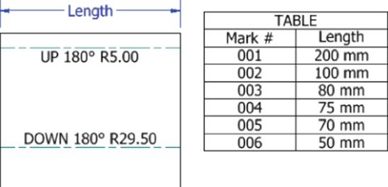
Figure 12.39 A tabulated iPart drawing
If you create a tabulated drawing in this manner and then add rows to the iPart/iAssembly table, your drawing table will automatically add the new rows as well. Rows can then be hidden in the table if needed simply by editing the table on the sheet and then right-clicking the row in the table editor and unselecting Visibility. You can close the file without saving changes.
Sharing Your Drawings Outside Your Workgroup
Once your design is fully annotated, you can share the design documents with others in numerous ways. Of course, the traditional hard-copy route is available from the Print tool, but there are electronic means to share your Inventor drawings with people who do not have Inventor. The native file formats offer several possibilities. Inventor IPT, IAM, IPN, and IDW files can be viewed using the freely distributed Inventor View application. A version of this is already installed with Inventor but can be downloaded for free from the Autodesk website.
As mentioned earlier, if you use DWG as your drawing-file format, anyone with a copy of AutoCAD or AutoCAD LT® 2007 software or newer can view, plot, and measure the Inventor drawing. There are object enablers on the Autodesk website that even allow older versions of AutoCAD to open Inventor DWG files.
Using the Publish tool you can generate a neutral DWF or DWFx file. The DWF or DWFx file can store both your 2D drawing and the 3D models referenced in the drawing. DWF files are viewed using Autodesk Design Review, which is available for download from the Autodesk website. To publish a DWF file, first click the Inventor button (the large I in the upper-left corner) and then select Export![]() Export To DWF.
Export To DWF.
You can find any of the products mentioned earlier by going to www.autodesk.com or www.google.com and searching for one of these terms:
· Autodesk Inventor View
· Autodesk Object Enabler
· Autodesk Design Review
PDF is a popular publishing format that can be read by Adobe Acrobat Reader. You can save a PDF from Inventor using the Save Copy As option and changing the file type to PDF or by using Export![]() Export To PDF. You can also download a number of PDF printer drivers that will allow you to print to PDF. Acrobat Reader is available for download from Adobe's website: www.adobe.com.
Export To PDF. You can also download a number of PDF printer drivers that will allow you to print to PDF. Acrobat Reader is available for download from Adobe's website: www.adobe.com.
There are some options for creating PDFs found by clicking the Options button in the Save Copy As dialog box when the file type is set to PDF. For instance, you might want to include all sheets in the PDF and create it in black and white. You can do so using the Options button. Unfortunately, you cannot configure these options to be the defaults.
You should note that the option to have the PDF viewer automatically open the PDF when it is created is a bit hidden and is set with the Publish options used when creating a DWF. To disable the automatic view of PDFs, click the Inventor button (the large I in the upper-left corner) and select Export![]() Export To DWF. Then uncheck the Display Published File In Viewer option.
Export To DWF. Then uncheck the Display Published File In Viewer option.
Additional Resources
In addition to the step-by-step information and exercises in this chapter, tutorials can be found by choosing the Get Started tab and looking in the Videos And Tutorials area.
The Bottom Line
1. Create templates and styles. Inventor provides numerous methods to create, store, and use drawing templates and styles. Careful planning as to how and where to manage these resources is important. Consideration must be given to how templates are deployed on your network and whether to use the style library.
1. Master It Rather than using one of the out-of-the-box drawing settings, you need to set up a drawing template, a drafting standard, and annotation styles to conform to a particular international, industry, or company drafting standard. How do you get started?
2. Utilize drawing resources. Each Inventor drawing file contains a number of commonly used drawing-resource definitions, such as title blocks, borders, symbols, and so on. These resource definitions allow you store preconfigured items for quick and easy reuse.
1. Master It You have blocks of general notes that you place on every drawing file. However, some drawings get one set of notes, and others get another, so making these notes part of the title block seems to be the wrong approach. Is there a way to handle this in Inventor?
3. Edit styles and standards. Inventor's drawing styles and standards allow you to set up your dimension styles, layer styles, and so on, in advance so that you can maintain consistency across all of your drawings.
1. Master It You have set up your object defaults to use an inch-based dimension style, but occasionally you want to place a millimeter-based dimension. Can this be done easily, or do you have to override the dimension style?
4. Create drawing views. Drawing views allow you to make 2D views of your 3D models. The hidden line generation and alignment of your projected views are automatic, as are updates to the 2D views when your 3D models change.
1. Master It When placing a drawing view, the lines on curved edges don't show up. Is there an option to turn these on?
5. Annotate part drawings. Adding annotation to your part drawings is accomplished primarily using the tools found on the Annotate tab. Many of these tools automate traditional drafting annotation, but you might still find the need to add annotation in a more manual way.
1. Master It You need to create sheet-metal flat patterns for your parts with laser etching on them. Often this is text, but you've noticed that if you attempt to create text as an extrusion on the part, you end up with a stencil effect, rather than single-line characters used for etching. Is there a way to do this?
6. Annotate assembly drawings. Often, much of the annotation created for assembly drawings concerns bill of materials information, but you can use most of the same annotation tools used for part drawings in an assembly drawing.
1. Master It You created a section view of your assembly model and then noticed that you could hide the hatch pattern by right-clicking it and choosing Hide. But now when you right-click the drawing view, you can't find an option to bring back the hatch pattern. Is it gone for good?
7. Work with sheet-metal drawings. Inventor sheet-metal drawings give you access to the folded model and the flat pattern, provided that a flat pattern has been created in the 3D model.
1. Master It When you place a bend note on a flat pattern drawing, it places the direction, angle, and bend radius. Your shop is accustomed to seeing only the direction and angle. Is there a way to remove the bend radius?
8. Work with weldment views. Weldment views offer some extra functionality over standard assembly views in that they allow you to document your assembly in each weldment stage.
1. Master It You want to create a drawing package that shows all of the weldment pieces in the prepped stage and then show the weldment assembly in the completed form. What's the best way to do this?
9. Work with iParts and iAssembly drawings. One of the benefits of creating part and assembly families as iParts and iAssemblies is the ability to created tabulated drawings that show each member and its key dimensions in a table.
1. Master It You've created an iPart table and want to set the dimension on the sheet to match the table heading. Is this possible?
10.Share your drawings outside your workgroup. You can save your drawings in DWF, DWFx, and PDF formats in order to share them with people who do not have Inventor. You can use Autodesk Design Review to access DWF files and Adobe Acrobat Reader to access PDF files; both are free viewer applications.
1. Master It You have a multipage Inventor drawing, but when you export it as a PDF file, you get only the first page. Is this a bug, or is it just the way it is?
All materials on the site are licensed Creative Commons Attribution-Sharealike 3.0 Unported CC BY-SA 3.0 & GNU Free Documentation License (GFDL)
If you are the copyright holder of any material contained on our site and intend to remove it, please contact our site administrator for approval.
© 2016-2025 All site design rights belong to S.Y.A.