Mastering Autodesk Inventor 2015 and Autodesk Inventor LT 2015 (2014)
Chapter 18. Routed Systems
This chapter will cover the tools of the routed systems environments found in the Autodesk® Inventor® Professional suite and the Inventor Routed Systems Suite. Inventor routed systems comprise two primary toolsets: tube and pipe, and cable and harness. The tube and pipe tools are used in routing pipe and hosing through mechanical assembly designs. The cable and harness tools are used for electrical design where routing wires and cables around obstacles and checking for fit are important.
In this chapter, you'll learn to
· Create routes and runs
· Author a tube and pipe component
· Author an electrical component
· Create and document cable and harness assemblies
Tube and Pipe
The tube and pipe tools are based on Inventor fundamental concepts such as sweeps, 3D sketch paths, adaptive parts, subassembly structure, and more. The tube and pipe tools automate many of these fundamentals, making the design of tube and pipe routes faster, more intuitive, and less tedious. However, it is best to have an understanding of these fundamental concepts before jumping into the tube and pipe tools so you can understand how Inventor does things and, therefore, how to proceed when required to manually adjust or repair your designs. A lack of understanding of these fundamentals can often bring inexperienced Inventor users to a screeching halt in their tube and pipe endeavors and may leave them with a perception that the tools just don't work. Therefore, in the following sections, you will explore how to create routes, runs, and general tube and pipe assembly structure and learn to work with tube and pipe styles.
Understanding Routes, Runs, and Assembly Structure
Understanding the way that tube and pipe assembly structure is created is an important part of successfully creating and managing your tube and pipe designs. There are three primary levels to any tube and pipe assembly.
· A top-level assembly
· A tube and pipe run assembly
· A run assembly
All tube and pipe designs are made up of runs. A run is a subassembly that contains one or more route paths, pipe or hose segments, and fittings. For instance, a standard hot-water supply line is a run.
When you begin a tube and pipe design, you start with a new assembly template and click the Tube And Pipe button on the Environments tab. Doing so opens the Create Tube & Pipe Run dialog box, prompting you to set a name and location for the tube and pipe run assembly file and the first run assembly file. Figure 18.1 shows the Create Tube & Pipe Run dialog box for a top-level assembly, named mi_18a_100, being created. You can also add a new tube and pipe assembly to an existing assembly.
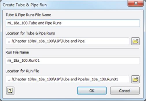
Figure 18.1 The Create Tube & Pipe Run dialog box
Notice that the default paths are created based on where the top-level assembly is stored. In this case, mi_18a_100.iam is stored in a subfolder of the Chapter 18 folder called mi_18a_100. The tube and pipe runs assembly is simply a container assembly created to contain the multiple runs you might create in the design. It is prefixed with the top-level assembly name and defaulted to a folder under it named the same as the top-level assembly and then AIP\Tube and Pipe.
The run assembly is prefixed with the top-level assembly name, given an incremental suffix (in this case 01), and defaulted to a subfolder named Run plus the increment number located in the same directory as the assembly. Although you can change this file structure per tube and pipe assembly, accepting the default does maintain a certain standardization of structure. Figure 18.2 shows the assembly browser structure and file structure of a tube and pipe design set to the default paths.
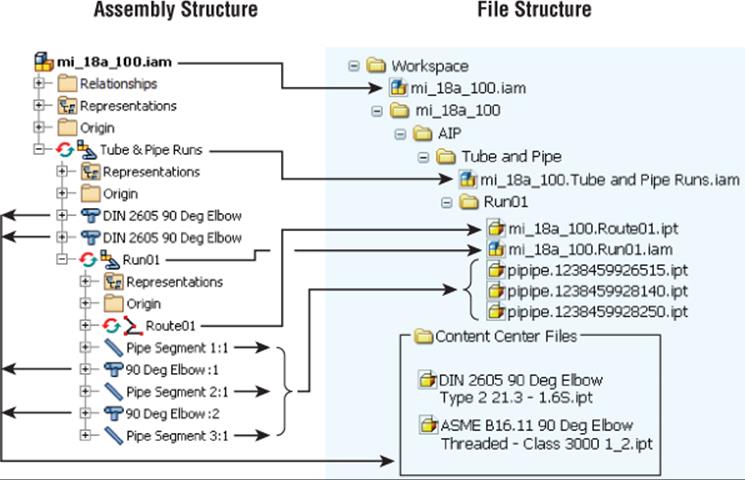
Figure 18.2 Assembly and file structure of tube and pipe design
Once a run is created, you can create a route within it. Routes are 3D paths created to define the path for pipes, tubes, or hoses to follow. In Figure 18.2, there are two elbow fittings (DIN 2605 90 Deg Elbow) that were placed outside the run and in the tube and pipe runs assembly. Route01 was then created as a component of Run01, starting from one of the DIN elbows and running to the other. Run01 consists of Route01, three pipe segments, and two 90-degree elbows.
Although the pipe segments and the route path files were saved under the Run01 folder, you'll notice that the elbow files were saved to the Content Center Files path. Because fittings such as elbows, tees, and couplings are generated from Content Center, these part files are automatically saved to the Content Center Files path defined in either your project file or your Application Options settings.
Here are a few things to note when working with tube and pipe runs:
· A unique part file is created for each pipe, tube, and hose segment in the run, even if more than one segment is the same length. Although this approach may seem a departure from what you'd expect, it is key to allowing runs to be edited downstream.
· Enter meaningful names for the runs and routes as you create them. As you create more complex designs, having multiple Route01s scattered throughout the assembly may create confusion during edits.
Exploring the Tube and Pipe Styles
Runs and routes are determined by tube and pipe styles. Properties such as material, diameter, and fitting types are set in the tube and pipe style. Rules such as minimum and maximum segment length can also be set in the style. The Inventor tube and pipe tools load with several default styles based on the ANSI, DIN, ISO, and JIS tube and pipe standards and the Parker hose and fittings. Styles fall into three primary categories:
1. Flexible Hose These are single hose segments connected by a start point and endpoint selection. The hose style can include, but is not required to have, fittings for the start and stop points.
2. Tubing with Bends This does not contain elbows and follows a default bend radius. The radius can be set per bend as needed. Minimum and maximum segment lengths are set in the style, and couplings are placed where segments connect.
3. Rigid Pipe with Fittings These styles are required to include 90-degree elbow fittings and can include 45-degree elbows, flanges, and couplings. There are three subcategories for rigid piping styles:
1. Self Draining These styles require a pipe, a coupling, a 45-degree elbow, a 90-degree elbow, and a custom elbow or tee to match the desired slope angle.
2. Butt Welded These styles require a pipe and a 90-degree elbow. Butt welded styles require a weld gap size.
3. Flanged These styles require a pipe, an elbow, a flange, and optionally a gasket.
4. Mixed Units If a flanged style is selected for rigid pipe, the Mixed Units option is enabled as a style choice for the end treatment. This option indicates that the style contains flanged fittings that use imperial units and metric units.
Figure 18.3 shows a flexible hose run, a rigid tubing run, and a rigid piping run, from top to bottom.
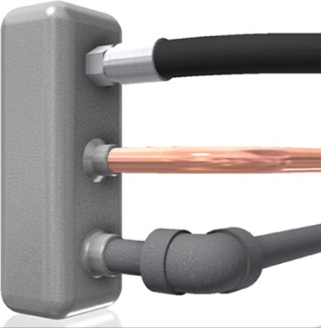
Figure 18.3 Hose, tube, and pipe runs
The Tube & Pipe Styles Dialog Box
You can access the Tube & Pipe Styles dialog box by using the master tube and pipe runs assembly, by using the run assembly, or by clicking the Tube And Pipe Styles button on the ribbon or using the default right-click context menu. The dialog box is divided into a pane on the left listing the styles and two tabs on the right controlling the general settings and the style rules. Figure 18.4 shows the Tube & Pipe Styles dialog box with a Hydraulic Hose style set active, denoted in bold. A second style is selected and has been right-clicked, showing the options that correspond with the buttons along the top of the dialog box.
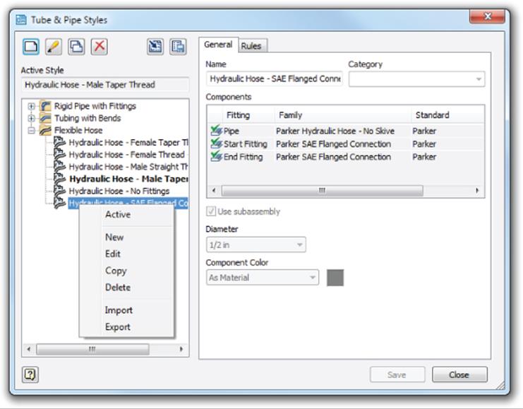
Figure 18.4 The Tube & Pipe Styles dialog box
When you're editing, copying, or creating a new style, some components may be either required or optional, depending on the style type. If the component is not specified and it is required, it will be marked with a red arrow next to it on the General tab. If it is empty and shows a gray arrow, it is optional. When the component is selected, the arrow will be green. Figure 18.5 shows a pipe style being created from scratch.
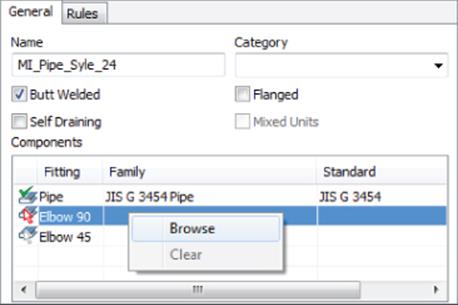
Figure 18.5 Creating pipe styles
This new style is a Butt Welded style and requires a pipe and a 90-degree elbow. The pipe has been selected, but the elbow is still required, as indicated by the red (dark) arrow. The 45-degree elbow is not required, and its optional status is indicated by the gray (light) arrow. In Figure 18.5 the user has right-clicked in the Elbow 90 row and selected Browse in order to specify the required elbow type. You can also double-click a row to open the style library browser.
In the style library browser, you can select from the list of available styles based on the size, schedule, and material settings made in the General tab and the availability from the Content Center library. You can set additional filtering in the style library browser. When you set the filter to a particular standard, the materials available for that particular standard are listed. If an asterisk is displayed, all the content for that setting is displayed.
Back in the Tube & Pipe Styles dialog box, you can specify a minimum and maximum size range for creating route segments on the Rules tab. I recommend you set the minimum segment length to at least 1.5 times the nominal diameter value to avoid minimum segment length violations that occur when pipe segments are too small in relation to the nominal diameter.
Each style type has different rule criteria:
· For Rigid tubes, you can set the default bend radius for the bends.
· For Flexible hoses, you can set a minimum bend radius and hose length round-up value.
· For Butt Welded pipe styles, you can set the gap size for the groove welds and control the display of the gaps in the graphics display and in drawings.
· For Butt Welded Flanged pipes, you can specify the coupling style.
· Fitting connections are determined by the end treatment set for the particular fitting.
· All other end treatments use a gap at segments and fitting joints.
Generally, it is best practice to set the style before creating routes and placing fittings. However, you can create and apply styles at any time. Styles can be set in a number of ways. You can change the active style for the tube and pipe assembly so that all new runs follow the style; you do this by selecting a style from the Style drop-down. Or you can change the style for the active route by setting that route as active and using the Style drop-down to select a different style. You cannot change a rigid pipe route to a flexible hose style or vice versa. To make such a change, you must delete the route and re-create it.
Authoring Tube and Pipe Components
Tube and pipe components, like components for other applications, require authoring before they can be published into Content Center. The tube and pipe authoring process is more complex because the router uses the component geometry. For example, the router needs to know the difference between a tee and an elbow, and it needs to know how much the connector overlaps the pipe.
If you have not already downloaded the Chapter 18 files from www.sybex.com/go/masteringinventor2015, please refer to the “What You Will Need” section of the introduction for the download and setup instructions. Once you have the files downloaded, you can follow this example to author a PVC pipe to an NPT adaptor:
1. On the Get Started tab, click the Open button and browse to the Chapter 18 directory in your Mastering Inventor 2015 folder.
2. Open the file mi_18a_010.ipt.
3. Switch to the Manage tab, and select the Tube And Pipe Authoring button from the drop-down list on the Author panel (it might be displaying Component by default). The Tube & Pipe Authoring dialog box displays, and the part changes to shaded wireframe display.
4. Select Adapters from the Type drop-down, as shown in Figure 18.6.
5. Change the number of connections, and observe that the connection buttons update to match. Confirm that Connections is set to 2.
6. Confirm that the End Treatment is set to Threaded and enter 1/2 in for the Nominal Size setting.
7. By default, the button for connection 1 is active. Select one of the circular edges to define the connection point. Click the Axis button and select the z-axis from the Origin folder in the browser. An arrow appears, showing the connection direction, as shown inFigure 18.7. The default connection type is Female, but you can set it to Male or Neutral (for flanged or butt-welded fittings).
8. The Engagement settings define the maximum and minimum overlap between the connector and pipe. The router needs a range because the pipe usually has a minimum length increment. The engagement range allows the router to adjust the position of the pipe in the fittings.
9. To determine the engagement, navigate to the Design Data folder (the default location is C:\Program Files\Autodesk\Inventor 2015\Design Data) and open Threads.xls. Select the NPT For PVC Pipe And Fitting tab. For tapered threads, the engagement value depends on how tightly the fitting is screwed onto the pipe. You need the maximum engagement value, so add the Handtight Engagement value, which is 0.32, and the Wrench Makeup, Internal value, which is 0.1429. Set Max to Distance, and enter 0.4629 for the total value. For Min, divide the Handtight Engagement value, 0.32, by the total engagement value, 0.4629, which comes to 69%.
10.Click the 2 button to define the other connection.
11.In this example, Socket Welded was chosen as the End Treatment setting since that seemed to be the best description. You should choose an end treatment that is consistent with your other parts.
12.Select a circle at the opposite end of the part for the connection point and select the z-axis again. You will see that the arrow points into the adapter and the orange line representing the engagement is outside the part. Using the flip/arrow button next to the Axis button, change the direction so that the arrow is to the outside and engagement is to the inside, as shown in Figure 18.8.
13.The depth of the socket is 0.84 inch. You don't want to design to full-depth engagement because of tolerances, so set Max to Distance and specify 0.75 as the depth. For Min, accept the default value of 50%.
14.The ISOGEN data is optional. For this exercise, this information will be left blank. Click the OK button to complete authoring the adapter.
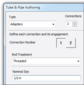
Figure 18.6 Setting the : fitting type
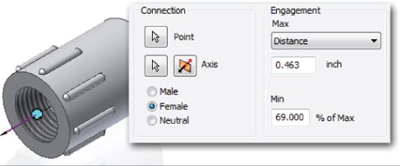
Figure 18.7 Defining the connection and engagement
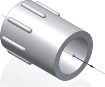
Figure 18.8 Connection direction and engagement
Now that the part has been authored as a tube and pipe adaptor, it is ready to be published to a read/write Content Center library. You can find more information on publishing parts to Content Center in Chapter 7, “Reusing Parts and Features.”
Placing Fittings
Fittings can be placed from Content Center or from a user-created directory of authored fittings. As a rule, you should use the place tools found on the Tube and Pipe tab rather than placing fittings as you would normal assembly parts. The place options on the Tube and Pipe tabs ensure that the authored connections are used as intended. Figure 18.9 shows the place options available on the Pipe Run tab.
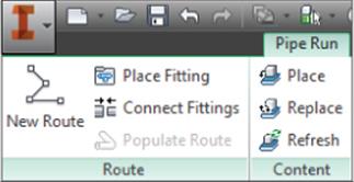
Figure 18.9 Place options available on the Pipe Run tab
When fittings are placed, either from Content Center or from a user-defined library of authored fittings, you can drag the fitting over the route segments or nodes, and you will see the placement point appear. Use the spacebar to toggle through available orientations if more than one exists. When you click to place the fitting, the Select Orientation tool appears, allowing you to rotate the orientation to the desired position.
You can edit connections by right-clicking them while the route is active for edits and choosing Edit Fitting Connections. In the Edit Connections dialog box, you can select a segment and then use the X button to remove the connection. You can also select Change Fitting Diameter, as shown in Figure 18.10.
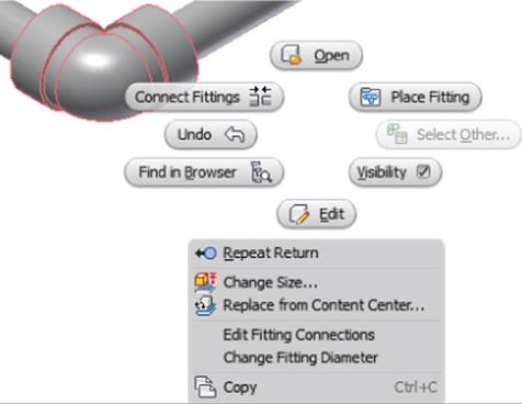
Figure 18.10 Editing fitting options
Quickly Place Fittings
If you need additional fittings that are identical to previously placed or populated fittings, you can select the fitting and then select the Place Fitting button from the Route panel. This will place a new fitting that matches the existing fitting. Note that you can do the same thing by selecting the fitting and right-clicking and choosing Place Fitting.
If your model contains a fitting of a certain size and you want to place the same family of fitting but in a different size, you can select the existing fitting and then select the Place button from the Content panel. This will open Content Center with that fitting family active, allowing you to double-click the family and select the new size.
Creating Routes
Routes define the path for pipe and hose segments and the corresponding fittings. Route paths can have a simple start point and endpoint or can include as many intermediate points as are required. Several tools and options are used to start and create route paths:
1. Authored Connection Points You can use any of the predefined connection points for any library fitting or custom-authored part. When you move your mouse pointer over the library fitting, the connection point(s) will highlight.
2. Circular Edges You can use any circular edge in the assembly to set the route point at the center of it with the exception of authored parts such as fittings. For those parts, only the authored connection points can be used.
3. Precise and Offset Start Points You can hover your mouse pointer over an edge to display a direction arrow. Running your mouse pointer along that arrow allows you to select the arrow to set the offset at that distance, or you can right-click and choose Enter Distance. If the arrow points in the wrong direction, you can use the spacebar to toggle it or right-click and choose Select Other Direction. Figure 18.11 shows the offset start point options.
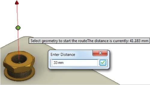
Figure 18.11 Offsetting a start point
Turning on Dynamic Prompts
You can watch the lower left of your screen to see the help prompts Inventor gives you as you select tools and hover over objects on the screen, or you can turn on Dynamic Prompts to place these tips at your cursor so they are more noticeable.
To turn on Dynamic Prompts, go to the Tools tab and click the Application Options button; then click the General tab, locate the Prompting Interaction area in the dialog box, and select the Show Command Prompting (Dynamic Prompts) option.
1. 3D Orthogonal Route Tool Once a start point is selected, run your mouse pointer along the projected axis and click or use the context menu's Enter Distance option to set a value for the second point. You will then be presented with the 3D Orthogonal Route tool. You can use the control handles to change the angle or rotate the control. The cross arrow toggles between 90-degree and 45-degree solutions, and the arc arrows allow you to rotate the route tool. You can also right-click and choose Custom Bend to enter an angle other than 90 or 45. When you enter a Custom Bend angle that cannot be accommodated with an elbow fitting, Inventor will place a bend in the tube or pipe segment. When the 3D Orthogonal Route tool is displayed, you can use the + and – keys to change the size of it on-screen. Figure 18.12 shows the 3D Orthogonal Route tool in use.
2. Route Nodes When placing a point along a route or setting an offset start point, you will see a colored dot tracking along the Route tool. If it is a yellow X, the offset is not enough to create a minimum segment as set in the style rules, and the point cannot be selected. If it is a blue dot, the segment might be too short to accommodate an elbow, but you are allowed to select it. If it is a green dot, the location is satisfactory to all of the style rules. You can right-click and choose Enter Distance to display an input box. InFigure 18.13, the node (which looks like a dot) at the left of the image shows the placement with a distance of 2200 mm entered.
3. Autoroute Options You can select the start point and endpoint of a route and use the Autoroute tool to flip through the available Autoroute solutions. You can also use this to close two parts of an already created route. Use the Select Other tool to toggle through all the Autoroute variations. Once an Autoroute is created, use the Move Segment button to adjust the segments and create new solutions. Figure 18.14 shows an Autoroute with a suggested variation.
4. Sketched Routes Route paths can also be based on an existing 3D sketch. These 3D sketches are used as the route by deriving the geometry into the route. Changes to the 3D sketch update the route automatically. You can use the Include Geometry tool to include any existing part edges in the route. You can also switch to the 3D Sketch tab while creating a route and use the standard 3D sketch tools to create route geometry as required. Whether routing in the tool or using a derived route, watch the visual cues offered by the sketch.
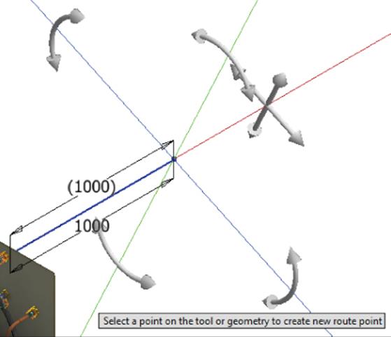
Figure 18.12 Using the 3D Orthogonal : Route tool
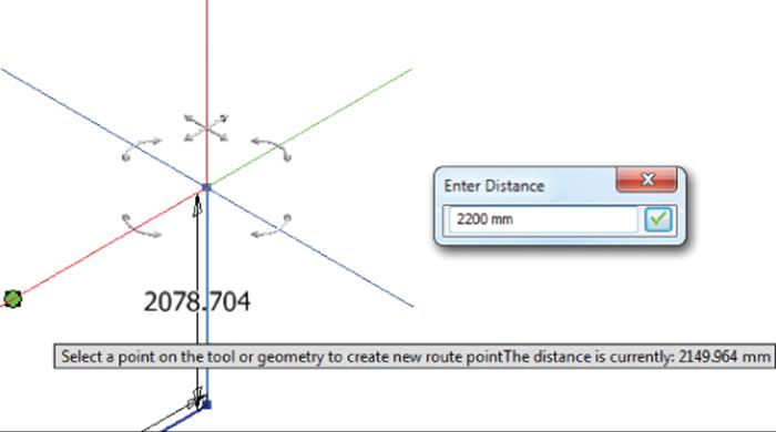
Figure 18.13 Route nodes
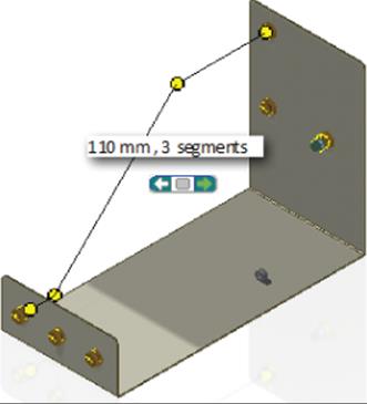
Figure 18.14 Autoroute and move segment options
Creating a Route from an Existing Sketch
Now you will use a combination of tools to create a pipe and tubing route based on an existing sketch:
1. On the Get Started tab, click the Open button and browse to the Chapter 18 directory in your Mastering Inventor 2015 folder.
2. Open the file mi_18a_015.iam.
3. From the Environments tab, select the Tube And Pipe button on the Begin panel.
4. Accept the defaults offered in the Create Tube And Pipe Run dialog by clicking the OK button.
In the browser you will see that a run has been created and it is active. There is also a specialized tab added to the ribbon named Pipe Run.
5. From the Manage panel of the Pipe Run tab, use the pull-down to select the B36.10M-ASME B16.11 – Steel Threaded Pipe style.
6. Select the New Route button from the Route panel.
7. Make note of the route part file location and then click the OK button to approve the default values for the Create Route dialog.
8. Another new tab will appear named Route. Select the Derived Route button from the Create panel.
9. Select the path that is already present in the assembly, as shown in Figure 18.15.
10.Right-click and select Done from the context menu to use the selected sketch as part of your pipe route.
This will add four route points to the route in the browser. Rather than focusing on all of the geometry, you'll use just the points, which improves the assembly performance for the initial calculations and updates.
11.Select the Finish Route tool from the Route tab to return to the Pipe Run tools.
12.From the Route panel, select the Populate Route button to create the pipe and fittings for this route.
13.Once the route is populated, you can select the Finish Tube And Pipe Run button. Your pipe run should look like Figure 18.16.
14.Select the Finish Tube And Pipe button on the Tube And Pipe tab to exit the tube and pipe environment and return to the top level of the assembly.
15.In the browser, expand the mi_18a_012 part in the browser and double-click the 3D sketch to edit it.
16.Change the 9-inch dimension in the sketch to 11.
17.Change the 135-degree dimension that does not have parentheses around it to 90, as shown in Figure 18.17.
18.Click the Finish Sketch button and then click the Return button to update the assembly and the pipe route that you created based on it.
19.Turn off the visibility of the 3D sketch by right-clicking the sketch in the browser.
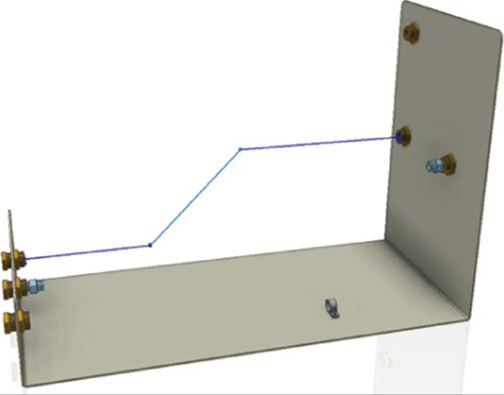
Figure 18.15 Selecting an existing 3D sketch as a piping route
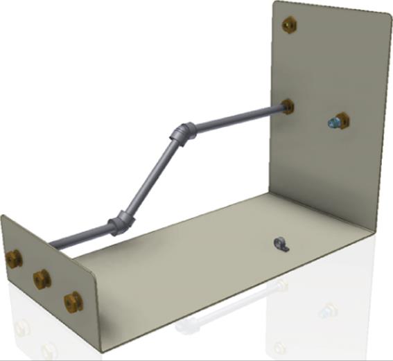
Figure 18.16 The piping run created from the 3D sketch
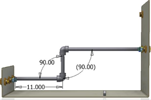
Figure 18.17 The updated 3D sketch
The use of a 3D sketch is not necessary to place a run like this, but it can be easier for some users to visualize the route before starting the routing tools. It is also a great tool for people who've used 3D sketches and sweep features to replicate piping runs in the past. You can save your work if you want to investigate the folders and file paths created, or you can close the file without saving changes and continue to the next set of steps.
Creating a Route Using the 3D Orthogonal Route Tool
Now you'll look at using the 3D Orthogonal Route tool to create a tubing section when no 3D sketch tool exists. To do so, open the file mi_18a_016.iam from the Chapter 18 directory. Then follow these steps:
1. From the Environments tab, select the Tube And Pipe button and click the OK button in the dialog to create a new run, noting that the run name has been incremented from the previous run.
2. In the Manage panel, set the style to ASTM B 88-ASME B16.22 – Soldered Copper Tubing.
3. Select the New Route button and click the OK button to accept the default naming.
4. Select the Route button from the Create panel.
5. Rotate the assembly so you can see the inside of the short flange of the base part. You will be working with the light-blue center fitting.
6. As you near the fitting's point of engagement, arrows indicating the initial direction of a run will appear. If you hover your cursor over the various circular edges of the fitting, you'll see the arrows flip directions. Select the option that will set the direction toward the fittings on the other flange of the base part, as shown in Figure 18.18, and click the mouse button when it is highlighted.
After the selection is made, a centerline will be displayed. Move your cursor along the line, and a dimension will display the distance from the selected point, as shown in Figure 18.19. You can increase the length of the line by pressing the + key on the keyboard, or you can use the keyboard to enter an explicit value. If you move your cursor to the 2.000 location or a location with a lower value, you'll see the selection indicator change to a yellow X. For anything above 2.000 the selection indicator will change to a green dot. This behavior is due to the bend radius default listed on the Rules tab of the Tube & Pipe Styles dialog box.
7. Type 7 on the keyboard to set the length and press Enter to create the first segment at 7 inches.
8. After the first segment appears and the route nodes appear, right-click in an open area of the design window and ensure that Rotation Snap is selected in the context menu.
Rotation Snap
The Rotation Snap option allows you to snap to the other fitting in the middle of the rotate action so that the angle is derived from the selections. If you happen to know the angle needed, you can simply click and drag the curved rotation arrow and enter an angle.
9. Click and drag the curved arrow on the green axis, move your mouse to the opposite fitting (as shown in Figure 18.20), and select that fitting.
Restarting a Route
If at any time during the creation of a route you make a mistake in selection, simply use the Undo button to back up a step, click the Route tool again, and click the end of your last route segment.
This method will align the route nodes to the second fitting and allows a great deal of flexibility in building a complex route.
10.Click the end of the second fitting to set an endpoint for the route.
11.This will present a preview of a route. The preview will include the number of segments and the Select Other tool so you can cycle between options.
12.Click the green arrows of the Select Other tool until you see the option that will create three segments and then click the green icon in the center of the Select Other tool to set the route.
13.Finish the route and then click the Populate Route button from the Pipe Run tab to populate the route with parts.
14.Select Finish Tube And Pipe Run.
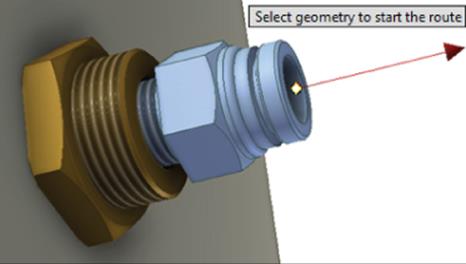
Figure 18.18 Setting the direction toward the other fittings
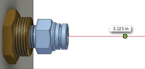
Figure 18.19 The preview allows you to visually place the end of the first segment
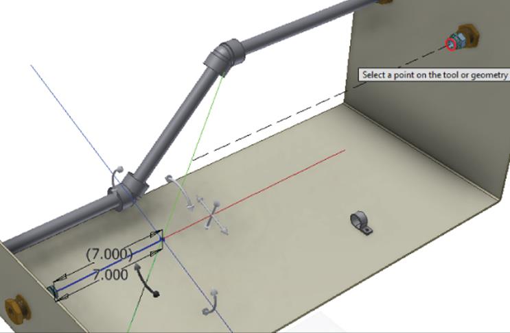
Figure 18.20 Rotation and point snaps aid in building between fittings
Using the 3D Orthogonal Route tool allows you to create a route based on existing geometry without the need to use an existing sketch. This can speed up the layout process and simplify your design. You can save your work if you want to investigate the folders and file paths created, or you can close the file without saving changes and continue to the next set of steps.
Creating a Flexible Hose Route
Flexible hose routes are similar to rigid pipe routes with just a few exceptions. Whereas a rigid pipe path is a series of line segments connected with arcs or points, a flexible hose path consists of a single spline segment. Flexible routes offer a couple of tools and options specific to this type of route, such as the ability to right-click a surface, select Enter Offset, and then adjust the hose length. You can open the file mi_18a_017.iam from the Chapter 18 directory and use the options in these steps to create a flexible hose route:
1. Locate and right-click the Tube & Pipe Runs 01 node in the browser and choose Edit.
2. Select the Create Pipe Run button and accept the defaults.
3. Set the style to Hydraulic Hose–Male Taper Thread.
4. Select the New Route button and click the OK button to accept the default naming.
5. Click the Route button.
With this style of hose, rather than selecting an existing fitting on which the hose will begin, you'll be asked to select the location for two fittings that will be placed before any routing options are offered.
6. Place the first fitting on the remaining unused anchor fitting on the small flange of the sheet-metal base part.
7. Place the second fitting on the last remaining fitting on the opposite side.
Placing the second fitting will generate the spline centerline of the hose. At this point you can create additional points offset from faces on the part or even use natural centers on curved faces to pass the hose through.
8. Select the curved edge of the hose retainer, as shown in Figure 18.21, to route the hose through the retainer.
9. Once the hose center is displayed, use the Hose Length tool in the Manage panel and use the slide bar to set the hose length to 44 inches.
10.Click the OK button to complete the path for the hose.
11.Finish and populate the route and then finish the tube and pipe run. Compare it to Figure 18.22.
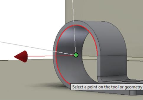
Figure 18.21 Routing the hose through a retainer
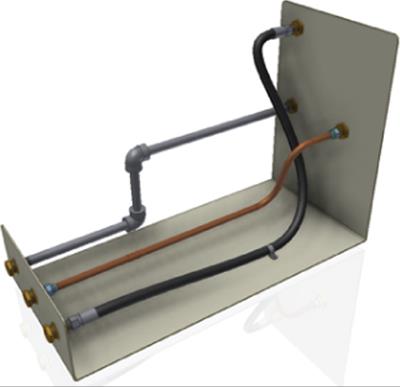
Figure 18.22 The completed routes
There are a number of options for creating these routes that you should explore. You also have the ability to add fittings inline. These added fittings will break the segments of pipes and tubes to create room for the fittings and set their engagement with the fittings automatically. If you later remove the fitting, the pipe will be “healed” and restored to a single segment.
Exporting ISOGEN Files
Often isometric centerline drawings are required for documentation of tube and pipe designs. The ISOGEN Output tool is available on both the Tube And Pipe tab and the Pipe Run tab. You can save all your tube and pipe runs as an ISOGEN (*.pcf) file directly from the master run assembly; just click the ISOGEN Output button on the Tube And Pipe tab. Or you can use the ISOGEN Output button while at an individual run level to save just that run. When flanged routes are created, gaskets are required for flanged connections if ISOGEN files are to be created from them.
Cable and Harness
The cable and harness tools in Inventor are based on the fundamental tools of part and assembly creation; however, the parts and assemblies created with the cable and harness tools are structured differently than standard part and assembly models. Understanding these differences requires a solid understanding of the way standard parts and assemblies are created and structured. In the following sections, you will explore the creation and placement of electrical parts, harnesses, wires, cables, and segments as well as how to copy and document cable and harness designs.
Creating and Placing Electrical Parts
You can use any Inventor model as an electrical connector by adding pin features specific to cables and harnesses to it. Parts can be created from scratch using standard modeling techniques or downloaded from supplier websites as well as a number of 3D content websites, such as http://mfgcommunity.autodesk.com/content/.
When downloading content from the Internet, you will often find models in other formats, such as STEP, IGES, SolidWorks, and so on. These files can be translated into Inventor files using the methods described in Chapter 14, “Exchanging Data with Other Systems.”
Authoring Electrical Components
The basic steps to turn a standard Inventor part into an electrical component are as follows:
1. Open the part file in Inventor.
2. Click the Place Pin button in the Harness panel of the 3D Model tab.
3. Select one of the following to place the pin:
· Center point of any circular edge, face, or hole
· Visible sketch points
· Work points
· Model vertex points
· Any model face
4. Enter a unique pin name/number.
5. Click the Harness Properties button in the pin-naming input box to enter additional pin properties if required.
6. Repeat steps 3 and 5 for each pin.
7. Click the Harness Properties tool in the Harness panel of the 3D Model tab.
8. Enter a reference designator (RefDes) placeholder. The RefDes property is intended to be used at the assembly level, where each instance of the connector will have a unique RefDes.
9. Select a Gender option (Male, Female, or None).
10.Set a wire offset point if required.
Creating a Connector
In the following steps, you will open an existing Inventor part file and create pins as just described. Figure 18.23 shows the Harness tools available in the parts environment.
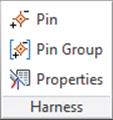
Figure 18.23 Harness part tools
Follow these steps to explore the steps used in creating a connector:
1. On the Get Started tab, click the Open button.
2. Browse for the file mi_18a_007.ipt in the Chapter 18 directory of the Mastering Inventor 2015 folder and open it.
3. Click the Place Pin button in the Harness panel of the 3D Model tab.
4. Select the visible sketch point.
5. Enter A1 in the Place Pin input box and click the Harness Properties button.
6. Select the Custom tab, click the Name drop-down, and select Embedded Length.
7. Enter 5 mm in the Value input box, click Add, and then click the OK button. Then click the green check mark or press Enter on the keyboard to set the pin.
8. To place the next pin, click the rounded edge on one of the top cutouts, enter A2 for the pin name, and then set the pin without entering any harness properties. Click the green check mark to set the pin.
9. Click roughly in the center of the blue square face to set the third pin and enter B1 for the name. Click the green check mark to set the pin.
10.Right-click and choose Done to exit the Place Pin tool.
11.In the Work Features panel of the 3D Model tab, click the Point button to create a work point.
12.Right-click and select Loop Select and then click the square profile edge for the remaining cutout. Be certain you are selecting the outer edge loop and not the inner loop.
13.Select the Place Pin tool again and select the work point you just created. Set the name to B2, right-click, and choose Done.
14.Edit Extrusion1 and change the Distance from 10 mm to 15 mm.
Notice which work points hold their positions relative to the geometry and which ones remain at the position in which they were created. You can right-click the pins that didn't update as expected and choose Redefine Feature or 3D Move/Rotate to adjust them. Understanding how pin locations will update is important when defining a connector part intended for use in iPart creation, where you will want the pin location to update as different pin sizes are created. For static pins not likely to change, nonassociative pins work just fine.
In addition to redefining the pin location, you can right-click any pin in the browser and choose Harness Properties to change the name or add/edit properties. Keep in mind that pin names must be unique.
Place Pin Groups
Although the Place Pin tool works well for defining pins not arranged in a pattern or for small numbers of patterned pins, you can use the Place Pin Group tool to place larger numbers of patterned pins. The following steps explore the Place Pin Group tool:
1. On the Get Started tab, click the Open button.
2. Browse for mi_18a_009.ipt in the Chapter 18 directory of your Mastering Inventor 2015 folder and open it.
3. Click the Place Pin Group button in the Harness panel of the 3D Model tab.
4. For Start Location, select WorkPoint1.
5. Enter 8 for the number of pins per row.
6. Enter 4.5 mm for the pin pitch (spacing) and then select an edge to establish the pin direction. Use the flip arrow if required.
7. Enter 2 for the number of rows.
8. Enter 4.5 mm for the row pitch and then select an edge to establish the pin direction. Use the flip arrow if required.
9. Enter A for the prefix letter and 101 for the start number.
10.Switch the radio button for the numbering scheme options to Sequential Column, then to Circumventing, and then back to Sequential Row to see the differences in each.
11.Click the OK button to set the pins. Figure 18.24 shows the Place Pin Group dialog box settings and pin group.
Notice the 16 pins created and listed in the Model browser. You can right-click any of the pins and choose Edit Pin Group to change the start point, spacing, and direction if required. You can also right-click and select Delete Pin Group to start over, or you can select Delete to remove an individual pin. Note too that you can right-click any of the pins and choose Redefine Feature to set an individual pin to a nonpatterned location.
As a final step, you will create four work points in front of the connector for use later as a stop point for the wire or cable segment.
12.Click the Point button on the Work Features panel of the 3D Model tab.
13.Right-click and ensure that Loop Select is not selected.
14.Click the edge of the visible work plane and then one of the work axes. You'll see a work point created at the intersection. Do the same for the remaining three axes and then right-click each axis and the plane and turn off their visibility.
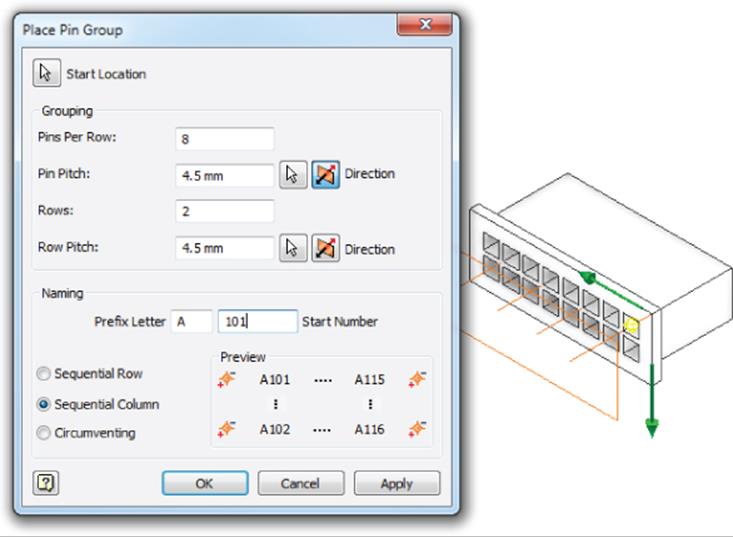
Figure 18.24 Creating a pin group
The work points allow you to place the end-of-wire segments appropriately off the connector. Figure 18.25 shows a connector utilizing a segment-end work point.
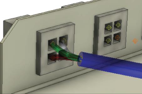
Figure 18.25 Work points for segment ends
Creating a Harness
Electrical components, including connectors, wires, and cables, are assembled and constructed within a harness subassembly. Although you can place connectors at any structure level within the assembly and route wires to them, as a rule you typically place connectors within the harness assembly when the harness and connectors are purchased together so that your BOM will reflect the harness as an item. The steps for creating and routing a wire harness are as follows:
1. In an assembly file, place and constrain connector parts that will not be part of the harness assembly into the assembly either at the top level or within a subassembly.
2. Click the Cable And Harness button on the Begin panel of the Environments tab.
3. Enter a name and location for the harness subassembly file to be created.
4. Place and constrain connectors to be part of the harness.
5. Use the Create Wire, Create Cable, or Create Ribbon Cable tool to connect the pins of the connectors.
6. Use the Create Segment tool to create wire bundles, routing them around geometry obstacles of other parts in the assembly.
7. Use the Route or Automatic Route tool to route the wires or cables through the segments (wire bundles).
8. Use the Create Splice tool to create wire or segment splices as required.
When a harness is created, it is composed of a harness assembly file and a harness part file of the same name. The part file is the container in which the wires, cables, and segments will be built as they are added. Both files make up the overall harness and are required for the harness to work. Inventor will warn you if you try to edit these files directly rather than through a top-level assembly using the wire harness tools.
In the following steps, you will open an existing Inventor assembly file, create a simple harness assembly, and then place connectors:
1. On the Get Started tab, click the Open button.
2. Browse for mi_18a_018.iam in the Chapter 18 directory of your Mastering Inventor 2015 folder and open it.
3. On the Environments tab, click the Cable And Harness button in the Begin panel.
4. Accept the default name and location for the new harness assembly, and click the OK button. Note the harness subassembly and part nodes listed in the browser.
5. Click the Assemble tab, and then click the Place Component button.
6. Browse for and locate the connector file mi_18a_004.ipt and click the Open button.
7. Click twice in the graphics area to place two instances of the connector; then right-click and select Cancel.
To assemble the connectors (residing in the subassembly) to the base part (residing in the top-level assembly), you'll need to return to the top-level assembly and place the constraints. Parts within the harness can constrain to the parts in the top-level assembly because the harness subassembly is adaptive.
8. Click the Finish Cable And Harness button to return to the top-level assembly.
9. Place an Insert constraint on the connectors and the holes on the outside flanges. Ensure that the connector pins face the inside of the base part.
10.Click the Finish Cable And Harness button to return to the top-level assembly. You can close this file when finished.
This simple exercise illustrates the steps required to create a harness subassembly and place connectors within it. You can also place connectors in the top-level assembly before creating the harness assembly and then demote components from the top-level assembly into the harness subassembly. To do so, follow these general steps:
1. Place the connectors in the top-level assembly.
2. Create the harness assembly.
3. While the harness subassembly is active, expand it in the browser.
4. Click the connector components in the browser and drag them down into the harness assembly.
Setting Global Harness Settings
You can access the settings for the entire harness by right-clicking the top-level node of the harness in the browser while it is active for edits.
Placing Wires
Once the harness assembly is created and the electrical connector parts are added and constrained, you can add wires and/or cables. When wires are created, you enter a unique wire ID name, select a wire category, and set the wire name (type). Then you select the two pins from which and to which you want to run a wire. To see how the Create Wire tool works, open mi_18a_020.iam in the Chapter 18 directory of your Mastering Inventor 2015 folder and follow these steps:
1. Double-click the harness subassembly to set it active for edits (or right-click it and choose Edit).
2. On the Cable And Harness tab, click the Create Wire button.
3. Set Wire ID to Wire101.
4. Select Generic from the Category drop-down.
5. Set the Name drop-down to 14AWG-BLK.
6. Select Pin 1 (work point) on one of the red connectors for the Pin 1 selection. You'll see the pin number when you pause your mouse pointer over the pin. Figure 18.26 shows the pin selection and wire settings.
7. Select pin 1 (work point) on the other red connector for the pin 2 selection.
8. Click Apply to set the wire. It should run in a straight line between the two connectors.
9. Set the remaining three pins for the red connectors as listed here:
· Pin 2 = Wire102, Generic 14AWG-RED
· Pin 3 = Wire103, Generic 14AWG-WHT
· Pin 4 = Wire104, Generic 14AWG-GRN
10.Click Cancel to exit the Create Wire dialog box.
11.In this assembly, a segment (blue wire bundle) has already been created. Click the Route button to route a wire through the segment.
12.Click just one of the wires for the Wires selection and then click the segment for the First Segment selection.
13.Select the Single Segment check box and then click Apply. Note that the segment will shrink to size based on the wire.
14.Click Cancel to exit the Route dialog box and then click the Automatic Route button.
15.In the Auto Route dialog box, select the All Unrouted Wires check box, and click the OK button.
16.Expand the Harness1 part node in the browser, and you'll notice a Wires folder containing all of the wires you created. Right-click Wire101, and choose Harness Properties. Browse the tab to examine the read/write and read-only properties available for this wire. When finished, return to the Occurrence tab, set Bend Radius to 2 × Diameter, and then click the OK button.
17.Right-click the Wires folder in the browser and select Bend Radius ![]() Check All Bend Radii.
Check All Bend Radii.
18.Note that you will receive a warning stating that one or more objects contain an empty bend radius. Click the OK button, and note that wires 102 through 104 are marked with a warning icon in the browser.
In this case, the warning indicates the bend radius has not been set. You can edit the wire property, set the bend radius, and then repeat the bend radii check. If the bend radius for each wire in the model is in compliance with the setting for that wire, then the check will clear. Editing segments will be covered later, in the section “Placing and Editing Segments.” Now that the problem area is identified, you could make the decision to either change the general layout of the assembly or edit the segment route to change the fit so that the bend isn't so sharp.
19.Click the Finish Cable & Harness button to return to the top-level assembly. You can close this file when finished.
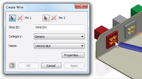
Figure 18.26 Placing a wire : on pin 1
This simple exercise demonstrated how to create wires in a harness and the routing of these wires in an existing segment. The wire categories and names listed in the Create Wires dialog box are drawn from the Cable & Harness library.
Using the Cable & Harness Library
The Cable & Harness library is located in the Design Data folder but can be set per harness. In most cases, you will want to configure it per the Inventor Design Data folder. You can set this option by right-clicking a harness assembly while it is active for edits, selecting Harness Settings, and then selecting the File Locations tab.
The library file that installs by default is Cable&HarnessDefaultLibrary.iwl. You can locate this file by checking the Design Data path in your Inventor project file (*.ipj) or by selecting the File tab of the Application Options dialog box. Recall that the project Design Data path trumps the application's Options path if set.
To add objects to the Cable & Harness library, click the Library button on the Manage panel of the Cable And Harness tab. You can add new wire, cable, and segment objects, just to name a few, and you can create your own custom object type. Figure 18.27 shows the library being edited.
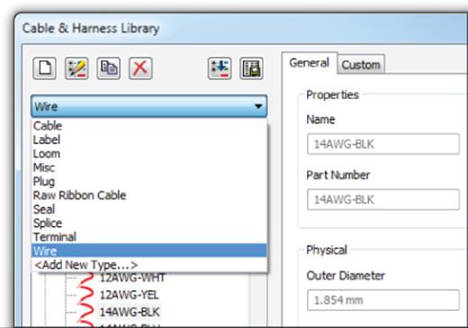
Figure 18.27 The Cable & Harness library
Placing Cables
Adding cables is much like adding wires. To explore the cable tools, open the file mi_18a_022.iam in the Chapter 18 directory of your Mastering Inventor 2015 folder. Then follow these steps:
1. Double-click the harness subassembly to set it active for edits, or right-click it and select Edit.
2. Click the Create Cable button on the Cable And Harness tab.
3. Set Cable ID to C201, and set Category to Alpha.
4. Select 2254/4 from the Name drop-down.
5. Note that Conductor ID 1 is set active. Select pin 1 (work point) on one of the gray connectors for the pin 1 selection. You'll see the pin number when you pause your mouse pointer over the pin.
6. Select pin 1 (work point) on the other gray connector for the pin 2 selection. Note that the conductor ID advances automatically to the next line.
7. Set the remaining three pins for the gray connectors as listed here:
· Pin 2 = C201:2, Red
· Pin 3 = C201:3, White
· Pin 4 = C201:4, Green
8. Click the OK button to set the cable.
9. Click the Automatic Route button, select the All Unrouted Wires check box, and click the OK button.
10.Expand the Cables folder in the browser and then right-click the listed cable and choose Harness Properties. Note that the bend radius is set to 10 × Diameter. If you click in the input box, you will see that the value is being pulled from the Cable & Harness library. Click the OK button to exit the dialog box.
11.Right-click the cable, and choose Bend Radius ![]() Check. Click the OK button in the warning dialog box.
Check. Click the OK button in the warning dialog box.
12.Note that the cable browser node has turned red and displays a warning sign next to it to indicate a problem. Right-click it in the browser, and select Bend Radius ![]() Show Violations. You will see a red marker on the segment in the graphics area along with a dialog box. Click the OK button.
Show Violations. You will see a red marker on the segment in the graphics area along with a dialog box. Click the OK button.
13.Click the Finish Cable And Harness button to return to the top-level assembly. You can close this file when finished.
The Check Bend Radius function allows you to locate problem areas with a design. You could remedy the violation here either by adjusting the segment points in an attempt to modify the fit of the cable route or by moving components and/or features in the assembly. Often a design might require adjusting both the assembly arrangement and the cable routing. But it's important to be able to check for bend radius violations so that you can determine what needs adjustment. In the next section, you will explore segment creation and editing.
Placing and Editing Segments
Segments are used to define the route path in which wires and cables will be run though a design to avoid interference and identify possible problem areas where bend radii may be too tight. A segment is created by selecting geometry on-screen, either outright or as an offset base. For each selection or offset point, a work point is created.
Once segments are created, you can refine them by adding points or redefining existing points. To explore the cable tools, open the file mi_18a_024.iam in the Chapter 18 directory of your Mastering Inventor 2015 folder. Then follow these steps:
1. Double-click the harness subassembly to set it active for edits, or right-click it and select Edit.
2. Click the Create Segment button on the Cable And Harness tab.
3. You will first run a route segment from the red to green connectors. Select the work point in front of the red connector for the start point of the segment.
4. Click any circular edge on the black grommet hole; this will select the center. Repeat this for the green grommet hole.
5. For the third point, you will specify an offset value and then select the flange with the two square-shaped notches along the top.
a. Right-click and choose Edit Offset.
b. Enter 10 mm in the Edit Offset box and then click the OK button.
c. Rub your mouse pointer around on different faces to observe the way the offset behaves. Then select roughly in the center of the face of the notched flange in front of the green connector.
6. Select the work point in front of the green connector.
7. Right-click and choose Continue.
8. Create another short segment from the orange connector and tie it into the first segment. Select the work point in front of the orange connector.
9. Click the work point at the center of the green grommet hole, and right-click and select Finish. Figure 18.28 shows the segments.
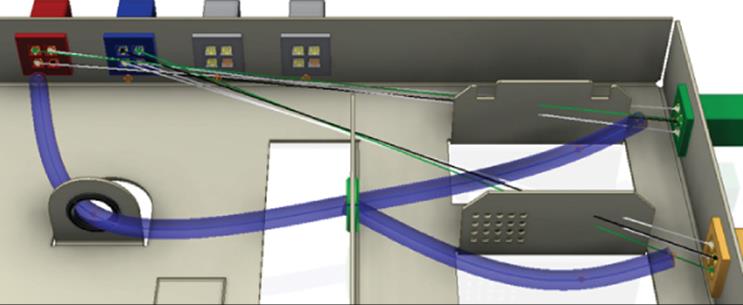
Figure 18.28 The created segments
Use the Automatic Route tool and select the All Unrouted Wires option to route the wires through the segments. Upon doing so, you'll notice two things:
· The segments adjust to compensate for the wire diameters.
· The cable coming off the blue connector has routed in an undesirable way.
Use the Unroute tool and select any of the wires at the blue connector. Because they all belong to a cable, you need to select only one, and then they all highlight. Once they are unrouted, you can use the Create Segment tool to create a new segment from the blue connector to the black grommet hole and then use Route or Automatic Route to reroute the cable.

Importing Wire Data from AutoCAD Electrical
Depending on the size and structure of your design department, you might want to import schematic data created by AutoCAD® Electrical software users. You can use the Import Harness Data tool in Inventor Professional or routed systems to connect multiple wires and cables in the harness assembly based on a schematic created in AutoCAD Electrical. A key to doing this successfully is making sure the wire and connector numbering is unique throughout the schematic. To do this, you must first export the harness data from AutoCAD Electrical as described in these steps:
1. On the Import/Export Data tab, click the Inventor button.
2. In the Export dialog box, specify the scope of the export (export the project or just the current drawing) and then click the OK button.
3. In the XML File Export dialog box, define the location and filename for the export file.
Once the data is exported from AutoCAD Electrical, you can import it into Inventor as described in these steps:
1. Double-click the harness assembly in which you want to import the harness data.
2. Check and/or assign reference designators on the connector and splice occurrences used in the harness data file to ensure that the names match the schematic.
3. Click the Import Harness Data button on the Cable And Harness tab. Then browse for the harness data file (.xml or .csv) exported from AutoCAD Electrical. If you're importing a CSV file, click Browse to locate the configuration file (.cfg).
4. Click the OK button to add the harness data to the active harness assembly.
The properties imported from AutoCAD Electrical are as follows:
· Component tags imported as RefDes
· Wire numbers imported as the wire ID
· The cable conductor wire layer imported as the cable ID
You'll notice that the middle section of the segment needs to be adjusted. To do so, follow these steps:
1. Run your mouse pointer over the centerline of the segment, right-click, and choose Add Points.
2. Select roughly in the middle of the segment and then right-click and select Finish.
3. Right-click the new work point and select Redefine Point.
4. Right-click, select Edit Offset, enter 10 mm for the offset value, and click the OK button.
5. Click roughly in the center of the square emboss on the base part.
6. Make an adjustment using the 3D triad. Right-click the same work point and select 3D Move/Rotate.
7. Click the blue cone (z-axis) of the triad, enter 4 mm, and then click Apply.
8. Select the small plane between the blue arrow and the green arrow (YZ plane), enter -6 mm in both the Y and Z inputs, and then click the OK button.
9. Edit the segment type. Select Assign Virtual Parts on the Cable And Harness tab and select the centerline of all the segments. From the Type drop-down, select Loom. Set the Category drop-down to Sample, set the Name drop-down to Wire Sleeve, click the Add button, and then click the OK button. Note that the selections in this dialog box are interdependent. For instance, you might need to set the category first to get the option selections for the name.
Segment Defaults
You set the default Edit Offset, Color Style, and Diameter settings, and more per harness by right-clicking the harness browser node, selecting Harness Settings, and then selecting the Segments tab.
Because the middle segment routes all the wires and the cable, it is larger in diameter. This is based on a setting in the harness properties. To determine its evaluated size, right-click the segment centerline and choose Harness Properties. You can determine the diameter at the bottom of the Occurrence tab. Because the grommet holes have an inside diameter of 10 mm, you can make a judgment as to whether a larger hole size is required.
On the Wire/Cables tab of the Segment Properties dialog box, you can review the wire and cable information. Double-clicking a line item will open the properties of that wire or cable. Figure 18.29 shows the properties of a wire contained in a segment.
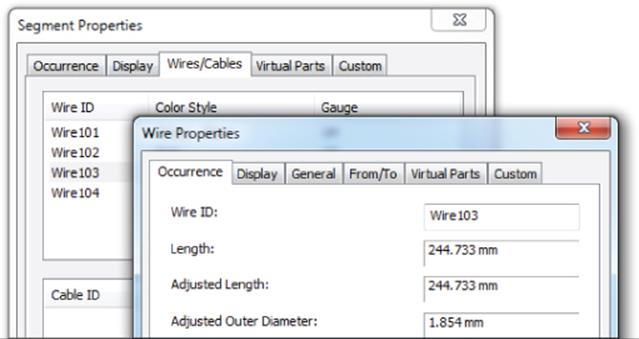
Figure 18.29 Wire properties
Copying Cable and Harness Designs
Because of the adaptive relationships between assemblies and the harness assemblies and their containing harness part file, copying existing harness and assembly designs must be done in a particular way so as not to break the adaptive relationship between the original files when working on the new files. Before looking at the steps to copy a harness, take a look at Figure 18.30 to understand the files involved. Each harness comprises an assembly file, where you can place connectors and other components, and a part file, where the wires, cables, segments, and other harness components are created.
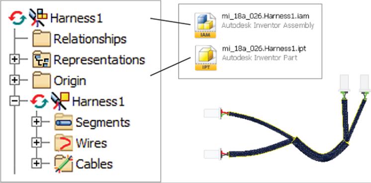
Figure 18.30 Harness assembly structure
To copy a harness design, open the file mi_18a_028.iam in the Chapter 18 directory of your Mastering Inventor 2015 folder. Then follow these steps:
1. Expand the assembly browser so that you can identify the harness assembly and part nodes.
Notice that the harness used in the assembly is called mi_18a_26. Harness2 and the part within is named the same. This is because this top-level assembly file was created by using the Save Copy As tool and, therefore, still references the original harness. Although it may seem logical to use the assembly Replace tool or some other method to swap out the harness, such methods can't be used because the adaptive relationships must be updated throughout the file references.
2. Right-click the mi_18a_26.Harness2.iam file in the browser, and choose Delete.
3. Click the No button in the prompt box so that adaptivity is not cleared in the original assembly.
4. On the Assemble tab, click the Place button.
5. Browse for the Harness_Files folder in the Chapter 18 directory, select mi_18a_26 .Harness1.iam, and click the Open button.
6. Click anywhere in the graphics screen to place the harness; then right-click and select OK or Cancel.
7. Typically, you would constrain the harness using assembly constraints at this point. For the purpose of this exercise, though, you don't have to do so. Instead, right-click the harness assembly in the browser and choose Make Adaptive. If prompted to save, click Yes.
8. In the Make Adaptive dialog box, you can set the new names for harness files or accept the default names.
9. In the Location area at the bottom of the dialog box, click the Browse button, browse for the Harness_Files folder in the Chapter 18 directory, and then click the OK button. Note that by default, a subdirectory of the same name as the top assembly is created along with subfolders for the component organization. You can accept this path and just make that part of your standard file management if you like.
10.Click the OK button and the new files are created, are made adaptive, and are ready for your design edits.
To make copies of a harness within the same assembly, you can simply copy and paste an existing harness, or you click an existing harness node and drag and drop it into the graphics area. Then right-click, choose Make Adaptive, and follow the renaming and location options detailed in the earlier steps.
Creating Nailboard Drawings
Documenting harnesses is a pretty straightforward process with purpose-built tools for detailing harnesses as traditional nailboard drawings. To explore these options, open the file mi_18a_026.iam in the Chapter 18 directory of your Mastering Inventor 2015 folder and follow these steps.
1. Double-click the harness subassembly to set it active for edits or right-click it and select Edit.
2. Click the Nailboard button on the Cable And Harness tab.
3. Select a drawing template of your choice from the Open Template dialog box and click the OK button.
4. You will be taken into an active sketch within the drawing. Click the Nailboard tab to switch to the nailboard sketch tools.
Switching to the Nailboard Tab
To use detailing tools specific to nailboard drawings, you must manually switch from the Sketch tab to the Nailboard tab once the nailboard view is created or edited. Using the Dimension tool on the Sketch tab will not give you the same results as using the Harness Dimension tool on the Nailboard tab.
5. Use the Harness Dimension tool to place dimensions from the points on the harness. These will display as driven sketch dimensions for now but will show as drawing style dimensions once out of sketch mode.
6. Click the Pivot button on the Nailboard tab and then select the sketch point at one of the 90-degree intersections. Then click a sketch endpoint of the harness leg and drag to pivot the angle. Right-click and choose Finish.
7. Zoom to any end on the harness, and select all of the wires (you can use a selection window to do this quickly).
8. Once the wires are selected, the Fan In and Fan Out buttons are available on the Nailboard tab. Click the Fan Out button, enter 180, and then click the OK button. Note the change in the wire fan angle. You can window the entire harness and use the Fan In/Out tools to set all the fans to the same angle as well. You can also manually click and drag each wire if needed.
9. Click the Finish Sketch button when you are satisfied with the dimensions, leg pivots, and fan angles.
10.Click the Place Connector Views button on the Nailboard tab.
11.Accept the defaults and click the OK button.
12.Note that a drawing view of each connector is placed near each wire fan. Right-click one of these views and select Edit View Orientation. Notice that you can change the styling, scale, and other properties, as you would with any Inventor view, but you can also change the view orientation.
13.Feel free to experiment with view settings and then click the OK button.
14.Click the Edit button on the Nailboard tab. If the Sketch tab becomes active, switch to the Nailboard tab.
15.On the Nailboard tab, click the Property Display button.
16.Set Selection Filter to All Wires.
17.Choose Wire ID from the Property Name list and then click Apply.
18.Click on-screen to establish the position of the ID label to the wire, and you will see all the wire ID labels placed. Click the OK button. Click and drag labels to adjust them.
19.Expand the Segment browser node, select all the listed segments, and then right-click and deselect the Display As Actual Diameter option.
20.Expand the Wires node, right-click one of the wires, and choose View Path. Notice how the wire path is highlighted.
21.Click the Finish Sketch button.
Here are a few more settings and options to use when working with nailboard drawings:
· Right-click the top-level harness node in the browser and choose Nailboard Settings to adjust the global settings of the nailboard view.
· You can open a drawing template first and use the Nailboard button on the Place Views tab to create a nailboard view and set the display settings, rotation, and other view options as you place the view.
· You can use the Table tool to place wire/pin tables from existing XLS files.
· You can use the Broken Sketch Entity tool in the drawing view sketch environment to break long harness runs so they will fit on the drawing sheet.
The Bottom Line
1. Create routes and runs. Using routed systems tools allows you to quickly define many different route types in order to check for clearance and fits within a design, all while creating a bill of materials that can be used downstream in the manufacturing process.
1. Master It You have a model containing equipment and structural components defining the space requirements for a new route. Can you create a route using this geometry, or are you required to create a sketch first?
2. Author a tube and pipe component. To create your own fittings, couplings, and so on to be used within tube and pipe design, you need to first author them for use with the tube and pipe tools.
1. Master It How can you set the depth at which pipe, tube, or hose segments are inserted into a fitting?
3. Author an electrical component. To create your own electrical connector components to be used within cable and harness designs, you need to first define pins within the parts.
1. Master It How can you create a family of electrical connectors with varying numbers of pins?
4. Create and document cable and harness assemblies. Cable and harness assemblies are created using a specific subassembly and part structure. Each harness is contained in a harness subassembly, and the parts such as wires, cables, and segments are created within a harness part file.
1. Master It You have a complex design that includes many harness assemblies and would like to turn some of them off while you work on others and/or create new ones. What is the best way to do this?