Software Engineering: A Methodical Approach (2014)
PART B. Software Investigation and Analysis
Chapter 7. Decision Models for System Logic
The previous chapter examined various system flow charts, which form part of the inventory of diagramming techniques employed by the software engineer. This chapter continues the discussion of diagrams by focusing on techniques used to represent and manage system logic. In the traditional FO paradigm, decisions are represented and analyzed by use of structured language (pseudo-code), decision tables or decision trees. In the more contemporary OO paradigm, the traditional methods are still applicable, but in addition to system rules. The main challenge is the identification of these decision issues; they are not always obvious. Here, skill and experience in information gathering are precious virtues.
The chapter will proceed with discussions in the following areas:
· Structured Language
· Decision Tables
· Decision Trees
· Which Technique to Use
· Decision Techniques versus Flowcharts
· System Rules
· Summary and Concluding Remarks
7.1 Structured Language
Decisions can be represented by use of structured English in pseudo-code-like manner. Use of the standard control structures for selection, iteration and recursion is common (you should be familiar with these you’re your earlier programming courses). As usual, indentation improves readability. It is assumed that you know how to write a pseudo-code; therefore, nothing further will be said on this matter. Decisions may also be presented in a tabular manner as illustrated in Figure 7-1.
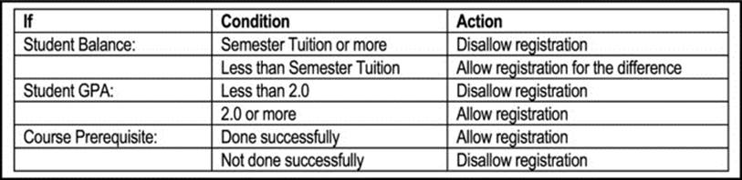
Figure 7-1. Decisions to be Taken on Student Registration at a College or University
7.2 Decision Tables
A decision table is a tabular technique for describing logical rules. It serves as an aid to creative analysis and expresses a business situation in a cause-effect relationship. The decision table provides an excellent means of communication between users and software developers. It forces the software engineer to be objective in the decision making process, and to consider all the decision alternatives. Figure 7-2 shows the basic components of a decision table.
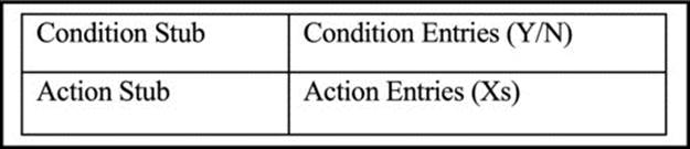
Figure 7-2. Structure of a Decision Table
7.2.1 Constructing the Decision Table
The following guidelines are useful in the construction of a decision table:
· Make small tables (maximum four conditions).
· All possible rules must be represented. A rule is simply a condition entry combined with an action entry.
· Every rule must have an action.
· Rules must be unique and independent.
· Define all alternate outcomes. In particular, note that N conditions => 2n outcomes (rules).
· Develop a set of conditions that yields each outcome.
· Assign a decision for each outcome.
Example 1: Consider as an example, an airline ticket seller is given the following guidelines:
1. There are two classes of tickets - first class and economy.
2. If a request is for first class and the space is available then reserve first class seats. If request is for economy and space available, reserve economy seat.
Figure 7-3 shows a faulty decision table for the situation described. In the figure, the guideline that states that every rule must have an action is not met; the table is therefore incorrect. Figure 7-4 shows a correct decision table. Notice that two additional conditions have been introduced.
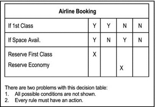
Figure 7-3. Incorrect Decision Table for Airline Problem
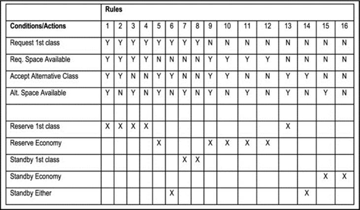
Figure 7-4. Correct Decision Table for Airline Problem
7.2.2 Analyzing and Refining the Decision Table
Two principles are used to analyze and refine the decision table: elimination of redundancies, and avoidance of ambiguities. Let us examine each.
Elimination of Redundancy: Redundancy occurs when two rules result in the same action and the condition entry responses are the same except for the last condition. The two rules can be combined (i.e. one is discarded). In Figure 7-4, rules 1&2, 3&4, 7&8, 9&10, 11&12, 15&16 constitute redundancies. For each pair, the second rule is eliminated; the revised table is shown in Figure 7-5.
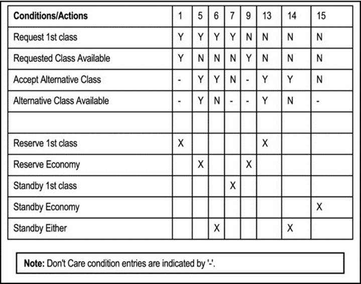
Figure 7-5. The Enhanced Decision Table for Airline Problem
Avoidance of Ambiguity: If two equivalent sets of conditions require different actions, the table is said to be ambiguous. Ambiguity occurs when don't care situations exist (indicated by dash (-)). Figure 7-6 illustrates. Ambiguities are also referred to as contradictions. When they occur, you must revisit the analysis that led to them, and make appropriate adjustments.
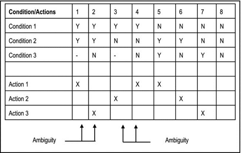
Figure 7-6. Illustration of Ambiguity
7.2.3 Extended Decision Table
In situations where the number of conditions exceeds four and/or each condition can have more than two outcomes, the decision table becomes large and unwieldy. In these cases an extended decision table can be useful.
Extended tables are normally used to save space. Figure 7-7 provides an example. Note that statement(s) made in the condition stub are incomplete so that both stub and entry must be combined in order to obtain the intended message.
Figure 7-7. Example of Extended Entry Decision Table
Extended-entry tables also reduce the possibility of redundancy and contradiction as Figure 7-8 illustrates. In this table, seven scenarios for action are represented, along with a default scenario, if none of the other seven scenarios is true. As an exercise, try to convert this to the most optimized system logic possible (you may represent the logic using pseudo-code, Pascal, C++ or Java). The exercise should also help you to see that the table can be further refined.
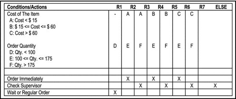
Figure 7-8. Extended Entry Decision Table for Inventory Ordering
7.3 Decision Trees
The decision tree is useful when complex branching occurs in a structured decision process, and it is essential to keep a string of decisions in a particular sequence. It therefore shows the relationship among decision factors. This is not shown by a basic decision table, and is poorly handled by a flowchart.
The decision tree used in software engineering and systems analysis is not as complicated as that used in management science, where probabilities and monetary expectations are shown. Essentially, the tree shows conditions and actions in a completely structured decision process.
Two symbols used are in the construction of a decision tree: an oval shape is used to symbolize if condition; a square shape symbolizes then action. Figure 7-9 illustrates a decision tree for a sale operation.
Decision trees are preferred to decision tables when any of the following situations hold:
· The process(es) concerned is (are) accomplished in stages.
· The logic is asymmetrical.
· The decision conditions and actions are related.
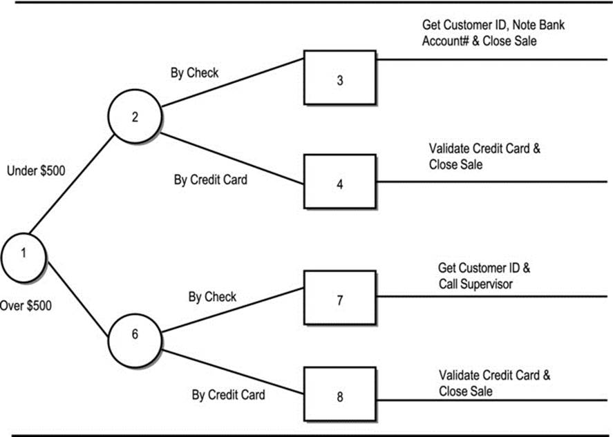
Figure 7-9. Decision Tree for a Sale Operation
Comparison of Decision Tree with Decision Table
How would you compare decision tables with decision trees? To get you started, here are some pointers:
· The decision tree emphasizes the sequential relation of decision conditions. This is impossible with the decision table.
· The decision tree handles quite effectively, situations where certain conditions and actions apply, given specific circumstances, but do not apply, given other circumstances. This is more difficult to illustrate via the decision table.
· The decision tree is more readily understood by users than the decision table.
· Unlike the decision table, the decision tree effectively handles scenarios involving more than four conditions.
· The decision table is more effective than the decision tree at avoiding redundancies and ambiguities. It is also more concise than the decision tree.
· The decision table is more easily incorporated in a CASE tool than a decision tree.
7.4 Which Technique to Use
Use structured language when any of the following holds:
· There are many repetitious conditions.
· Communication to end-users is paramount.
Use decision tables when any of the following holds:
· Complex combinations of conditions, actions and rules exist.
· A method that effectively avoids impossible situations, redundancies and contradictions is required.
· There are no more than four condition entries.
Use extended decision tables when any of the following holds:
· There are more than four condition entries.
· It is desirous to save space by representing the decision scenarios in a concise manner.
· There are (or may be) conditions that have more than two possible outcomes.
· It is desirous to reduce/eliminate redundancies and ambiguities.
Use decision trees when any of the following holds:
· The sequence of conditions and actions is critical.
· Not every condition is relevant to every action (branches are different).
· There are more than four condition entries.
7.5 Decision Techniques versus Flowcharts
Following is a comparison between decision techniques as discussed in this chapter and flow charts as discussed in the previous chapter. The comparison is based on advantages and disadvantages of both sets of methodologies.
Flowcharts provide the following advantages:
· Flowcharts are useful in identifying bottlenecks, delay factors, redundancies, and other system flaws.
· They are effective in depicting the movement of data.
· They are also effective in depicting transitions between system states.
· They are useful in the representation of system logic.
· They are superb in emphasizing the interrelatedness of system components – subsystems, operations, data storage, user interfaces, etc.
· They are excellent for easy communication with end users.
The following disadvantages are associated with flowcharts (if a CASE tool that supports the diagrams is used, these disadvantages are minimized):
· Flowcharts can be difficult to draw, especially for large, complex systems. Diagrams may be quite complex, particularly when there are several paths to consider.
· It may be difficult to determine whether the total problem is covered or whether superior alternate methods exist.
· Revision may be as difficult as drawing a complicated chart.
Decision techniques provide the following advantages:
· Structured format makes for easy drawing and clarity of presentation.
· Applications involving complex interactions of input variables are well documented and represented in a simple manner.
· Diagrams used are easy to revise and maintain with or without CASE.
· There is easy communication with end users.
The following disadvantages are associated with decision techniques:
· With decision techniques, there is no indication of the movement of data.
· They do not assist in identifying system bottlenecks, redundancies or delays as flowcharts.
· They do not represent system state transitions.
· The do not show the interrelatedness of the system components, only decision conditions.
Decision techniques and flow chart techniques are most effective when they are used to complement each other. The software engineer decides which techniques will be used to represent different aspects of the system. In an integrated CASE environment, these tools are all integrated as the system is modeled.
7.6 System Rules
Figure 7-10 proposes a ten-step approach for the development of software using the OO paradigm. The upper portion of the diagram relates to the requirements specification (RS), and was introduced in chapter 4 (Figure 4-1). The lower portion relates to the design specification (DS) and the actual development; we are yet to discuss these issues (discussion of the DS commences in chapter 9). As can be seen, the specification of system rules begins in the first portion of the schedule (item 5). These rules are subsequently refined and applied appropriately during the second portion of the schedule (item 8). Rules form an integral part of the system logic. The rest of this section focuses on essential details you should know about system rules.
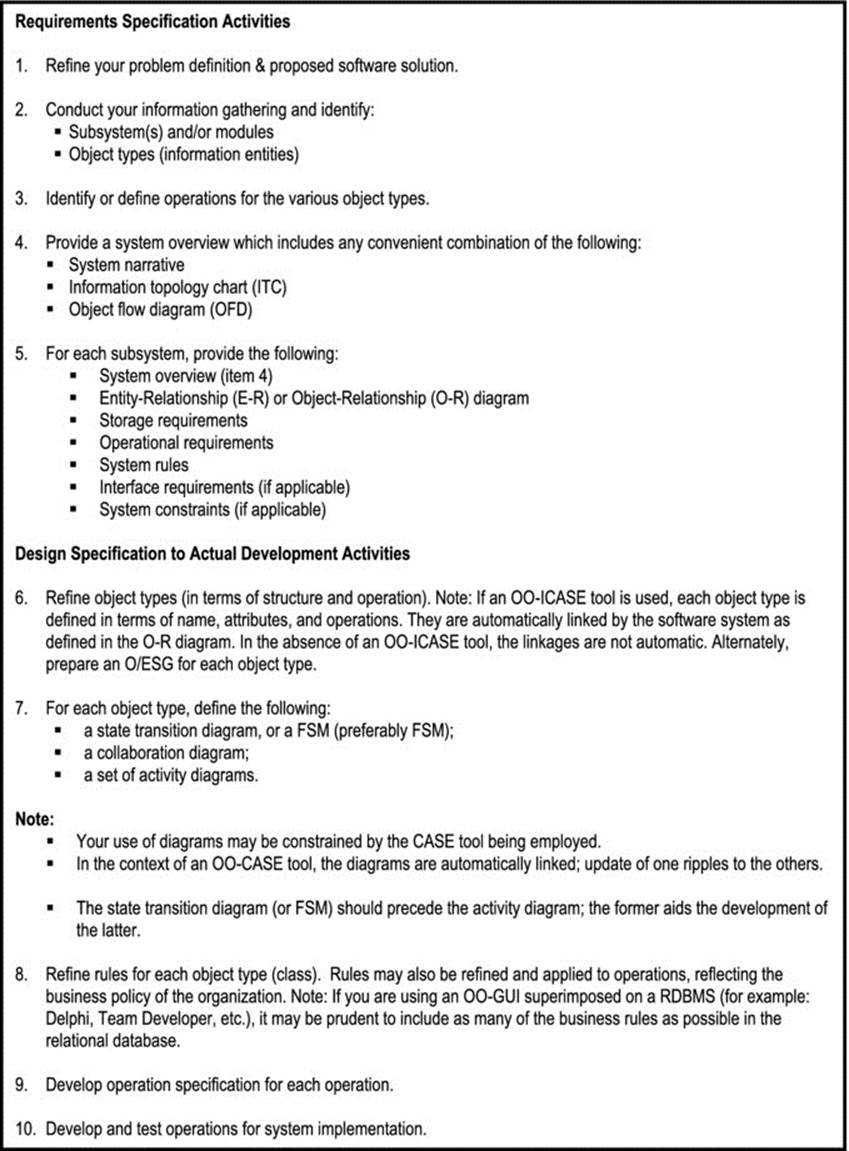
Figure 7-10. The OO Software Construction Process
Before proceeding, we need to define two new terms in the OO paradigm:
· Object Structure Analysis (OSA) includes all analysis that relate to the structure of object types comprising the software system.
· Object Behavior Analysis (OBA) includes all analysis that relate to the behavior of system operations comprising the software system.
Martin’s OO modeling pyramid (see [Martin, 1993]) identifies four levels of information engineering activities in the organization: enterprise modeling, business area analysis, system design, and system construction; it also shows how OSA and OBA are related to these activities. The term information engineering simply refers to a focused area of software engineering that relates to the efficient operation of business organizations (see appendices 3 and 4). Based on Martin’s OO pyramid, Figure 7-11 has been prepared. It also helps you to have a better appreciation of the schedule presented in Figure 7-10.
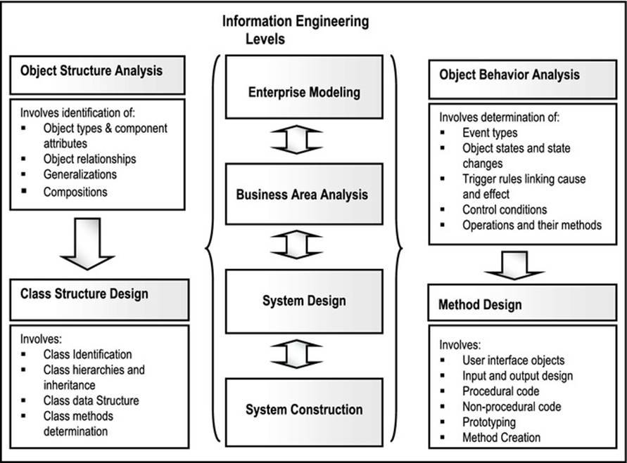
Figure 7-11. OO Modeling Pyramid
7.6.1 Rule Definition
A rule is a guideline for the successful and acceptable implementation of a process or set of operations. Failure to observe the rule could result in unacceptable system results. With traditional software engineering methodologies, rules are usually hidden in the code of system functions. In the OO paradigm (thanks to non-procedural languages), we want to define rules as an integral (encapsulated) part of the definition of (the operations of) a class. Code is then automatically generated from this.
Examples of Non-procedural Languages:

Rules are particularly helpful in designing the desired behavior of the system objects. They represent the laws about how the business is run. Rules may be in any of the following broad categories:
· Relating to object structure analysis (OSA) and inter-object relationships (business rules).
· Relating to object behavior analysis (OBA) and business policies of the organizations.
Rules must be rigorous, precise, concise, clear, and easily understood by end-users.
Example 2: The following is an example of an OBA rule:
![]()
7.6.2 Declarative versus Procedural Statements
Conventional programming languages are procedural. Declarative languages declare facts and rules, without specifying processing procedure. Declarative statements are more concise and easier to understand and validate than procedural statements.
Example 3: Suppose that we are storing information about students in a database file called Student. Assume further that the property StudGPA stores the GPA of the student. The following SQL statement produces a logical view (called DeanList) of all students with a GPA of at least 3.6:
![]()
Because declarative statements are more flexible, it is preferable to build systems from declarative languages linked to OO-CASE tools, rather than procedural languages.
With an OO-CASE tool, rules are constructed with the use of a rule editor. Code is automatically generated so the rule can be executed immediately. Two examples of such products are LiveModel (previously called are Object Management Workbench) from Intellicorp and Rational Rose from Rational Software (now a division of IBM).
7.6.3 Types of Rules
Lee’s [Lee, 2002] refinement of Martin’s [Martin, 1993] categories of system rules include eight (8) categories as described below:
· Data Integrity Rule: A rule of this type states that condition about an attribute must be true (for example, marital status must be married, single, widowed, separated or divorced).
· Relationship Integrity Rule: Such a rule states that something about a relationship between two object types must be true (for example, a department cannot have more than 25 employees).
· Derivation Rule: A derivation rule prescribes a relationship between a dependent variable and a set of independent variables; it typically relates to calculated values (for example InvoiceAmount = Summation of Price * Quantity for each line item on the invoice).
· Pre-condition Rule: This type of rule states that a condition must be true before an operation is executed (for example, an employee object cannot be fired unless it is in a state of Hired).
· Post-condition Rule: This type of rule states the condition(s) which must exist after an operation is performed (for example, after the FireEmployee operation is executed, the stat of the employee object is Fired).
· Action Trigger Rule: A rule of this type defines the causal relationship between an event and the Operation that triggers it (for example, when the result of an interview is recorded, the appropriate action, commensurate with the recommendation, must be taken).
· Data Trigger Rule: This type of rule defines the causal relationship between an attribute’s status and an action (for example, when a student’s GPA falls below 2.0, send an alert letter).
· Control Condition Rule: Such a rule handles the situation in which an operation is caused by multiple triggers. The control condition rule determines what combination of circumstances will cause the operation to execute (e.g., if the student’s GPA is below 2.0 AND the student has registered for more than 12 credits, him/her student on probation).
Traditionally, data integrity rules, relationship integrity rules, and derivation rules are described as business rules. The term stimulus/response rules is sometimes used to refer to action trigger rules, data trigger rules, and control condition rules.
Figure 7-12 provides the recommended constructs for the different types of rules. Figure 7-13 provides some examples.
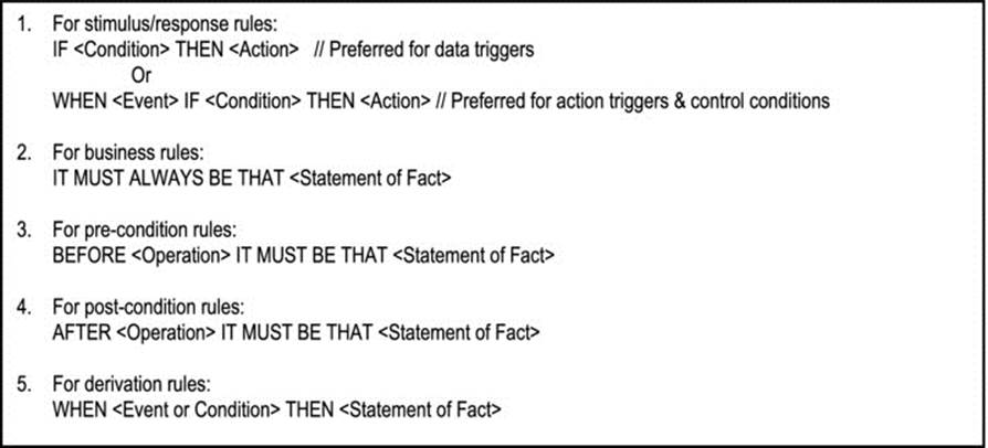
Figure 7-12. Recommended Constructs for Different Types of Rules
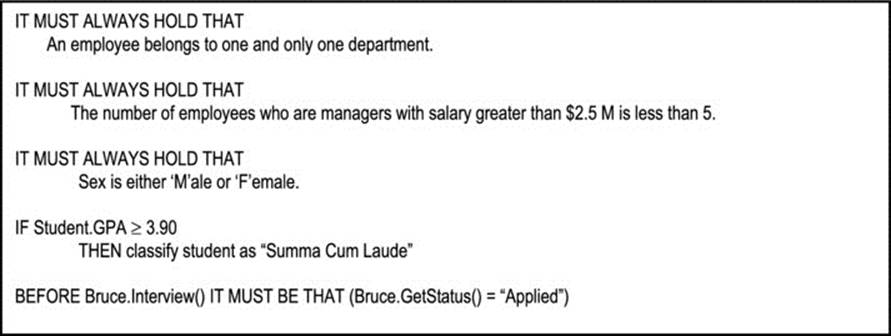
Figure 7-13. Examples of Rules
7.7 Summary and Concluding Remarks
Let us summarize what has been discussed in this chapter:
· The traditional methods of representing decisions are via structured language, decision tables and decision trees.
· The structured language may be in the form of pseudo-code or a tabular representation. It is applicable in simple situations where communication to end-users is of paramount importance.
· The decision table has four main sections: the condition stub, the condition entries, the action stub and the action entries. The decision table must be free of redundancies and ambiguities. Decision tables are useful in situations where there are complex combinations of four or less conditions, and it is desirable to efficiently represent all the possibilities while avoiding ambiguities as well as redundancies.
· The extended decision table is a modification of the basic decision table in order to provide more flexibility. It is particularly useful in any combination of the following situations: more than four conditions exist; not all the conditional possibilities are relevant; and it is desirable to be concise but accurate.
· The decision tree is a hierarchical graphical representation of the decision problem. It is useful in any combination of the following situations: the sequence of conditions and actions is critical; not every condition is relevant to every action (i.e. the branches are different); there are more than four condition entries.
· A system rule is a guideline for the successful and acceptable implementation of a process or set of processes.
· There are eight types of rules: data integrity rules, relationship integrity rules, derivation rules, pre-condition rules, post-condition rules, action trigger rules, data trigger rules and control condition rules.
· Rules must be clearly specified according to predetermined formats.
Traditionally, expert systems were based on an important component called the inference engine.
An inference engine is a collection of facts and rules about a specific area of knowledge and facilitates deductions based on established techniques of logical reasoning. Special software was used for recording of such facts.
Object technology facilitates the easy, more pragmatic construction of inference engines for expert systems. It’s also more exciting.
Some rules are to be visible to end users, so that they may check them in a workshop. These include business policy rules, derivation rules. There are other rules that are best kept invisible (transparent) to the end user, to avoid confusion. These include rules for technical design, integrity rules, rules internal to the software (OO-CASE tool and/or Repository) being used.
Mastery of the techniques discussed since chapter 3 places the software engineer in an excellent position to prepare an impressive RS. This time, your RS should have a refined project schedule. The next chapter will provide guidelines on how to achieve this. Before you proceed, take a second look at the sample requirements specification included in appendix 9; it should provide you with useful insights.
7.8 Review Questions
1. What are the decision techniques that have been discussed in this chapter? What circumstance(s) would warrant the use of each technique?
2. Consider the registration process at your institution, or a similarly complex process at an organization that you are familiar with:
· Identify the different circumstances (conditions) that must be considered.
· Determine an appropriate action for each circumstance.
· Represent your findings using one of the decision techniques discussed in the chapter.
· Develop a software application to address the problem, using Delphi, Visual C++, C++ Builder, or any other RAD tool that you are familiar with.
3. What is a system rule? Briefly describe the different types of rules discussed.
4. Still considering the registration process at your institution, answer the following questions:
a. Assume that there is an operation called Student.RegisterCourse. What pre-condition might exist for registering for a particular course?
b. Assume that there is an operation called Student.FindGPA that calculates the GPA of a student from and array field Student.Grades which contains the student’s grades. Propose a derivation rule for the GPA.
7.9 References and/or Recommended Readings
[Jacobson, 1992] Jacobson, Ivar. Object Oriented Software Engineering: A Use Case Approach. Boston, MA: Addison-Wesley, 1992.
[Kendall, 2005] Kendall, Kenneth E. and Julia E. Kendall. Systems Analysis and Design 6th ed. Upper Saddle River, NJ: Prentice Hall, 2005. See chapter 9.
[Lee, 2002] Lee, Richard C. and William M. Tepfenhart. Practical Object-Oriented Development With UML and Java. Upper Saddle River, NJ: Prentice Hall, 2002. See chapters 9.
[Martin, 1993] Martin, James and James Odell. Principles of Object Oriented Analysis and Design. Eaglewood Cliffs, NJ: Pretence Hall, 1993. See chapter10.
[Pfleeger, 2006] Pfleeger, Shari Lawrence. Software Engineering Theory and Practice 3rd ed. Upper Saddle River, NJ: Prentice Hall, 2006. See sections 4.4 and 14.3.
All materials on the site are licensed Creative Commons Attribution-Sharealike 3.0 Unported CC BY-SA 3.0 & GNU Free Documentation License (GFDL)
If you are the copyright holder of any material contained on our site and intend to remove it, please contact our site administrator for approval.
© 2016-2026 All site design rights belong to S.Y.A.