Computer Organization and Design (2016)
APPENDIX A
Assemblers, Linkers, and the SPIM Simulator
James R. Larus, Microsoft Research, Microsoft
Abstract
This appendix describes the process by which a human-readable program is translated into a form that a computer can execute, provides a few hints about writing assembly programs, and explains how to run these programs on SPIM, a simulator that executes MIPS programs.
Keywords
assembler, linker, SPIM, simulator, MIPS R2000, assembly language, machine language, macro, unresolved reference, link editor, assembler directive, source language, external label, global label, local label, forward reference, symbol table, backpatching, text segment, data segment, relocation information, absolute address, formal parameter, separate compilation, static data, stack segment, register use convention, procedure call convention, caller-saved register, callee-saved register, procedure call frame, recursive procedures, interrupt handler, virtual machine
Fear of serious injury cannot alone justify suppression of free speech and assembly.
Louis Brandeis, Whitney v. California, 1927
A.1 Introduction
A.2 Assemblers
A.3 Linkers
A.4 Loading
A.5 Memory Usage
A.6 Procedure Call Convention
A.7 Exceptions and Interrupts
A.8 Input and Output
A.9 SPIM
A.10 MIPS R2000 Assembly Language
A.11 Concluding Remarks
A.12 Exercises
A.1 Introduction
Encoding instructions as binary numbers is natural and efficient for computers. Humans, however, have a great deal of difficulty understanding and manipulating these numbers. People read and write symbols (words) much better than long sequences of digits. Chapter 2 showed that we need not choose between numbers and words, because computer instructions can be represented in many ways. Humans can write and read symbols, and computers can execute the equivalent binary numbers. This appendix describes the process by which a human-readable program is translated into a form that a computer can execute, provides a few hints about writing assembly programs, and explains how to run these programs on SPIM, a simulator that executes MIPS programs. UNIX, Windows, and Mac OS X versions of the SPIM simulator are available on the CD.
Assembly language is the symbolic representation of a computer’s binary encoding—the machine language. Assembly language is more readable than machine lan guage, because it uses symbols instead of bits. The symbols in assembly language name commonly occurring bit patterns, such as opcodes and register specifiers, so people can read and remember them. In addition, assembly language permits programmers to use labels to identify and name particular memory words that hold instructions or data.
machine language
Binary representation used for communication within a computer system.
A tool called an assembler translates assembly language into binary instructions. Assemblers provide a friendlier representation than a computer’s 0s and 1s, which simplifies writing and reading programs. Symbolic names for operations and locations are one facet of this representation. Another facet is programming facilities that increase a program’s clarity. For example, macros, discussed in Section A.2, enable a programmer to extend the assembly language by defining new operations.
assembler
A program that translates a symbolic version of instruction into the binary version.
macro
A pattern-matching and replacement facility that pro vides a simple mechanism to name a frequently used sequence of instructions.
An assembler reads a single assembly language source file and produces an object file containing machine instructions and bookkeeping information that helps combine several object files into a program. Figure A.1.1 illustrates how a program is built. Most programs consist of several files—also called modules— that are written, compiled, and assembled independently. A program may also use prewritten routines supplied in a program library. A module typically contains references to subroutines and data defined in other modules and in libraries. The code in a module cannot be executed when it contains unresolved references to labels in other object files or libraries. Another tool, called a linker, combines a collection of object and library files into an executable file, which a computer can run.
unresolved reference
A reference that requires more information from an outside source to be complete.
linker
Also called link editor. A systems program that com bines independently assembled machine language programs and resolves all undefined labels into an executable file.
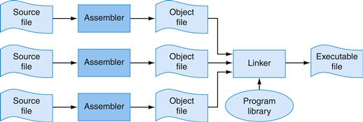
FIGURE A.1.1 The process that produces an executable file.
An assembler translates a file of assembly language into an object file, which is linked with other files and libraries into an executable file.
To see the advantage of assembly language, consider the following sequence of figures, all of which contain a short subroutine that computes and prints the sum of the squares of integers from 0 to 100. Figure A.1.2 shows the machine language that a MIPS computer executes. With considerable effort, you could use the opcode and instruction format tables in Chapter 2 to translate the instructions into a symbolic program similar to that shown in Figure A.1.3. This form of the routine is much easier to read, because operations and operands are written with symbols rather than with bit patterns. However, this assembly language is still difficult to follow, because memory locations are named by their address rather than by a symbolic label.

FIGURE A.1.2 MIPS machine language code for a routine to compute and print the sum of the squares of integers between 0 and 100.
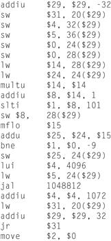
FIGURE A.1.3 The same routine written in assembly language.
However, the code for the routine does not label registers or memory locations nor include comments.
Figure A.1.4 shows assembly language that labels memory addresses with mnemonic names. Most programmers prefer to read and write this form. Names that begin with a period, for example .data and .globl, are assembler directives that tell the assembler how to translate a program but do not produce machine instructions. Names followed by a colon, such as str: or main:, are labels that name the next memory location. This program is as readable as most assembly language programs (except for a glaring lack of comments), but it is still difficult to follow, because many simple operations are required to accomplish simple tasks and because assembly language’s lack of control flow constructs provides few hints about the program’s operation.
assembler directive
An opera tion that tells the assembler how to translate a program but does not produce machine instructions; always begins with a period.
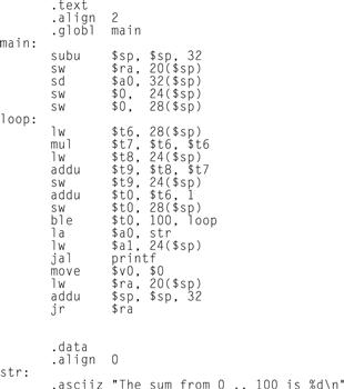
FIGURE A.1.4 The same routine written in assembly language with labels, but no comments.
The commands that start with periods are assembler directives (see pages A-47–49). .text indicates that succeeding lines contain instructions. .data indicates that they contain data. .align n indicates that the items on the succeeding lines should be aligned on a 2n byte boundary. Hence, .align 2 means the next item should be on a word boundary. .globl main declares that main is a global symbol that should be visible to code stored in other files. Finally, .asciiz stores a null-terminated string in memory
By contrast, the C routine in Figure A.1.5 is both shorter and clearer, since variables have mnemonic names and the loop is explicit rather than constructed with branches. In fact, the C routine is the only one that we wrote. The other forms of the program were produced by a C compiler and assembler.
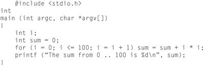
FIGURE A.1.5 The routine written in the C programming language.
In general, assembly language plays two roles (see Figure A.1.6). The first role is the output language of compilers. A compiler translates a program written in a high-level language (such as C or Pascal) into an equivalent program in machine or assembly language. The high-level language is called the source language, and the compiler’s output is its target language.
source language
The high-level language in which a pro gram is originally written.
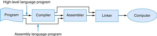
FIGURE A.1.6 Assembly language either is written by a programmer or is the output of a compiler.
Assembly language’s other role is as a language in which to write programs. This role used to be the dominant one. Today, however, because of larger main memories and better compilers, most programmers write in a high-level language and rarely, if ever, see the instructions that a computer executes. Nevertheless, assembly language is still important to write programs in which speed or size is critical or to exploit hardware features that have no analogues in high-level languages.
Although this appendix focuses on MIPS assembly language, assembly programming on most other machines is very similar. The additional instructions and address modes in CISC machines, such as the VAX, can make assembly programs shorter but do not change the process of assembling a program or provide assembly language with the advantages of high-level languages, such as type-checking and structured control flow.
When to Use Assembly Language
The primary reason to program in assembly language, as opposed to an available high-level language, is because the speed or size of a program is critically important. For example, consider a computer that controls a piece of machinery, such as a car’s brakes. A computer that is incorporated in another device, such as a car, is called an embedded computer. This type of computer needs to respond rapidly and predictably to events in the outside world. Because a compiler introduces uncertainty about the time cost of operations, programmers may find it difficult to ensure that a high-level language program responds within a definite time interval—say, 1 millisecond after a sensor detects that a tire is skidding. An assembly language programmer, on the other hand, has tight control over which instructions execute. In addition, in embedded applications, reducing a program’s size, so that it fits in fewer memory chips, reduces the cost of the embedded computer.
A hybrid approach, in which most of a program is written in a high-level language and time-critical sections are written in assembly language, builds on the strengths of both languages. Programs typically spend most of their time executing a small fraction of the program’s source code. This observation is just the principle of locality that underlies caches (see Section 5.1 in Chapter 5).
Program profiling measures where a program spends its time and can find the time-critical parts of a program. In many cases, this portion of the program can be made faster with better data structures or algorithms. Sometimes, however, significant performance improvements only come from recoding a critical portion of a program in assembly language.
This improvement is not necessarily an indication that the high-level language’s compiler has failed. Compilers typically are better than programmers at producing uniformly high-quality machine code across an entire program. Programmers, however, understand a program’s algorithms and behavior at a deeper level than a compiler and can expend considerable effort and ingenuity improving small sections of the program. In particular, programmers often consider several procedures simultaneously while writing their code. Compilers typically compile each procedure in isolation and must follow strict conventions governing the use of registers at procedure boundaries. By retaining commonly used values in registers, even across procedure boundaries, programmers can make a program run faster.
Another major advantage of assembly language is the ability to exploit specialized instructions—for example, string copy or pattern-matching instructions. Compilers, in most cases, cannot determine that a program loop can be replaced by a single instruction. However, the programmer who wrote the loop can replace it easily with a single instruction.
Currently, a programmer’s advantage over a compiler has become difficult to maintain as compilation techniques improve and machines’ pipelines increase in complexity (Chapter 4).
The final reason to use assembly language is that no high-level language is available on a particular computer. Many older or specialized computers do not have a compiler, so a programmer’s only alternative is assembly language.
Drawbacks of Assembly Language
Assembly language has many disadvantages that strongly argue against its widespread use. Perhaps its major disadvantage is that programs written in assembly language are inherently machine-specific and must be totally rewritten to run on another computer architecture. The rapid evolution of computers discussed in Chapter 1 means that architectures become obsolete. An assembly language program remains tightly bound to its original architecture, even after the computer is eclipsed by new, faster, and more cost-effective machines.
Another disadvantage is that assembly language programs are longer than the equivalent programs written in a high-level language. For example, the C program in Figure A.1.5 is 11 lines long, while the assembly program in Figure A.1.4 is 31 lines long. In more complex programs, the ratio of assembly to high-level language (its expansion factor) can be much larger than the factor of three in this example. Unfortunately, empirical studies have shown that programmers write roughly the same number of lines of code per day in assembly as in high-level languages. This means that programmers are roughly x times more productive in a high-level language, where x is the assembly language expansion factor.
To compound the problem, longer programs are more difficult to read and understand, and they contain more bugs. Assembly language exacerbates the problem because of its complete lack of structure. Common programming idioms, such as if-then statements and loops, must be built from branches and jumps. The resulting programs are hard to read, because the reader must reconstruct every higher-level construct from its pieces and each instance of a statement may be slightly different. For example, look at Figure A.1.4 and answer these questions: What type of loop is used? What are its lower and upper bounds?
Elaboration
Compilers can produce machine language directly instead of relying on an assembler. These compilers typically execute much faster than those that invoke an assembler as part of compilation. However, a compiler that generates machine language must perform many tasks that an assembler normally handles, such as resolving addresses and encoding instructions as binary numbers. The tradeoff is between compilation speed and compiler simplicity.
Elaboration
Despite these considerations, some embedded applications are writ ten in a high-level language. Many of these applications are large and complex programs that must be extremely reliable. Assembly language programs are longer and more difficult to write and read than high-level language programs. This greatly increases the cost of writing an assembly language program and makes it extremely difficult to verify the correctness of this type of program. In fact, these considerations led the Department of Defense, which pays for many complex embedded systems, to develop Ada, a new high-level language for writing embedded systems.
A.2 Assemblers
An assembler translates a file of assembly language statements into a file of binary machine instructions and binary data. The translation process has two major parts. The first step is to find memory locations with labels so that the relationship between symbolic names and addresses is known when instructions are translated. The second step is to translate each assembly statement by combining the numeric equivalents of opcodes, register specifiers, and labels into a legal instruction. As shown in Figure A.1.1, the assembler produces an output file, called an object file, which contains the machine instructions, data, and bookkeeping information.
An object file typically cannot be executed, because it references procedures or data in other files. A label is external (also called global) if the labeled object can be referenced from files other than the one in which it is defined. A label is local if the object can be used only within the file in which it is defined. In most assemblers, labels are local by default and must be explicitly declared global. Subroutines and global variables require external labels since they are referenced from many files in a program. Local labels hide names that should not be visible to other modules—for example, static functions in C, which can only be called by other functions in the same file. In addition, compiler-generated names—for example, a name for the instruction at the beginning of a loop—are local so that the compiler need not produce unique names in every file.
external label
Also called global label. A label referring to an object that can be referenced from files other than the one in which it is defined.
local label
A label referring to an object that can be used only within the file in which it is defined.
Local and Global Labels
Example
Consider the program in Figure A.1.4. The subroutine has an external (global) label main. It also contains two local labels—loop and str—that are only visible with this assembly language file. Finally, the routine also contains an unresolved reference to an external label printf, which is the library routine that prints values. Which labels in Figure A.1.4 could be referenced from another file?
Answer
Only global labels are visible outside a file, so the only label that could be referenced from another file is main.
Since the assembler processes each file in a program individually and in isolation, it only knows the addresses of local labels. The assembler depends on another tool, the linker, to combine a collection of object files and libraries into an executable file by resolving external labels. The assembler assists the linker by providing lists of labels and unresolved references.
However, even local labels present an interesting challenge to an assembler. Unlike names in most high-level languages, assembly labels may be used before they are defined. In the example, in Figure A.1.4, the label str is used by the la instruction before it is defined. The possibility of a forward reference, like this one, forces an assembler to translate a program in two steps: first fnd all labels and then produce instructions. In the example, when the assembler sees the la instruction, it does not know where the word labeled str is located or even whether str labels an instruction or datum.
forward reference
A label that is used before it is defined.
An assembler’s first pass reads each line of an assembly file and breaks it into its component pieces. These pieces, which are called lexemes, are individual words, numbers, and punctuation characters. For example, the line
ble $t0, 100, loop
contains six lexemes: the opcode ble, the register specifer $t0, a comma, the number 100, a comma, and the symbol loop.
If a line begins with a label, the assembler records in its symbol table the name of the label and the address of the memory word that the instruction occupies. The assembler then calculates how many words of memory the instruction on the current line will occupy. By keeping track of the instructions’ sizes, the assembler can determine where the next instruction goes. To compute the size of a variable-length instruction, like those on the VAX, an assembler has to examine it in detail. However, fixed-length instructions, like those on MIPS, require only a cursory examination. The assembler performs a similar calculation to compute the space required for data statements. When the assembler reaches the end of an assembly file, the symbol table records the location of each label defined in the file.
symbol table
A table that matches names of labels to the addresses of the memory words that instructions occupy.
The assembler uses the information in the symbol table during a second pass over the file, which actually produces machine code. The assembler again examines each line in the file. If the line contains an instruction, the assembler combines the binary representations of its opcode and operands (register specifiers or memory address) into a legal instruction. The process is similar to the one used in Section 2.5 in Chapter 2. Instructions and data words that reference an external symbol defined in another file cannot be completely assembled (they are unresolved), since the symbol’s address is not in the symbol table. An assembler does not complain about unresolved references, since the corresponding label is likely to be defined in another file.
The BIG Picture
Assembly language is a programming language. Its principal difference from high-level languages such as BASIC, Java, and C is that assembly language provides only a few, simple types of data and control flow. Assembly language programs do not specify the type of value held in a variable. Instead, a programmer must apply the appropriate operations (e.g., integer or floating-point addition) to a value. In addition, in assembly language, programs must implement all control flow with go tos. Both factors make assembly language programming for any machine—MIPS or x86—more difficult and error-prone than writing in a high-level language.
Elaboration
If an assembler’s speed is important, this two-step process can be done in one pass over the assembly file with a technique known as backpatching. In its pass over the file, the assembler builds a (possibly incomplete) binary representation of every instruction. If the instruction references a label that has not yet been defined, the assembler records the label and instruction in a table. When a label is defined, the assembler consults this table to find all instructions that contain a forward reference to the label. The assembler goes back and corrects their binary representation to incorporate the address of the label. Backpatching speeds assembly because the assembler only reads its input once. However, it requires an assembler to hold the entire binary representation of a program in memory so instructions can be backpatched. This requirement can limit the size of programs that can be assembled. The process is complicated by machines with several types of branches that span different ranges of instructions. When the assembler first sees an unresolved label in a branch instruction, it must either use the largest possible branch or risk having to go back and readjust many instructions to make room for a larger branch.
backpatching
A method for translating from assembly language to machine instructions in which the assembler builds a (possibly incomplete) binary representation of every instruction in one pass over a program and then returns to fill in previously undefined labels.
Object File Format
Assemblers produce object files. An object file on UNIX contains six distinct sections (see Figure A.2.1):
■ The object file header describes the size and position of the other pieces of the file.
■ The text segment contains the machine language code for routines in the source file. These routines may be unexecutable because of unresolved references.
■ The data segment contains a binary representation of the data in the source file. The data also may be incomplete because of unresolved references to labels in other files.
■ The relocation information identifes instructions and data words that depend on absolute addresses. These references must change if portions of the program are moved in memory.
■ The symbol table associates addresses with external labels in the source file and lists unresolved references.
■ The debugging information contains a concise description of the way the program was compiled, so a debugger can find which instruction addresses correspond to lines in a source file and print the data structures in readable form.
text segment
The segment of a UNIX object file that contains the machine language code for routines in the source file.
data segment
The segment of a UNIX object or executable file that contains a binary representation of the initialized data used by the program.
relocation information
The segment of a UNIX object file that identifies instructions and data words that depend on absolute addresses.
absolute address
A variable’s or routine’s actual address in memory.
![]()
FIGURE A.2.1 Object file.
A UNIX assembler produces an object file with six distinct sections.
The assembler produces an object file that contains a binary representation of the program and data and additional information to help link pieces of a program. This relocation information is necessary because the assembler does not know which memory locations a procedure or piece of data will occupy after it is linked with the rest of the program. Procedures and data from a file are stored in a contiguous piece of memory, but the assembler does not know where this memory will be located. The assembler also passes some symbol table entries to the linker. In particular, the assembler must record which external symbols are defined in a file and what unresolved references occur in a file.
Elaboration
For convenience, assemblers assume each file starts at the same address (for example, location 0) with the expectation that the linker will relocate the code and data when they are assigned locations in memory. The assembler produces relocation information, which contains an entry describing each instruction or data word in the file that references an absolute address. On MIPS, only the subroutine call, load, and store instructions reference absolute addresses. Instructions that use PC-relative addressing, such as branches, need not be relocated.
Additional Facilities
Assemblers provide a variety of convenience features that help make assembler programs shorter and easier to write, but do not fundamentally change assembly language. For example, data layout directivesallow a programmer to describe data in a more concise and natural manner than its binary representation. In Figure A.1.4, the directive
.asciiz “The sum from 0 .. 100 is %d\n”
stores characters from the string in memory. Contrast this line with the alternative of writing each character as its ASCII value (Figure 2.15 in Chapter 2 describes the ASCII encoding for characters):
.byte 84, 104, 101, 32, 115, 117, 109, 32
.byte 102, 114, 111, 109, 32, 48, 32, 46
.byte 46, 32, 49, 48, 48, 32, 105, 115
.byte 32, 37, 100, 10, 0
The .asciiz directive is easier to read because it represents characters as letters, not binary numbers. An assembler can translate characters to their binary representation much faster and more accurately than a human can. Data layout directives specify data in a human-readable form that the assembler translates to binary. Other layout directives are described in Section A.10.
String Directive
Example
Define the sequence of bytes produced by this directive:
.asciiz “The quick brown fox jumps over the lazy dog”
Answer
Macro is a pattern-matching and replacement facility that provides a simple mechanism to name a frequently used sequence of instructions. Instead of repeatedly typing the same instructions every time they are used, a programmer invokes the macro and the assembler replaces the macro call with the corresponding sequence of instructions. Macros, like subroutines, permit a programmer to create and name a new abstraction for a common operation. Unlike subroutines, however, macros do not cause a subroutine call and return when the program runs, since a macro call is replaced by the macro’s body when the program is assembled. After this replacement, the resulting assembly is indistinguishable from the equivalent program written without macros.
Macros
Example
As an example, suppose that a programmer needs to print many numbers. The library routine printf accepts a format string and one or more values to print as its arguments. A programmer could print the integer in register $7 with the following instructions:
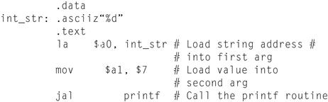
The .data directive tells the assembler to store the string in the program’s data segment, and the .text directive tells the assembler to store the instructions in its text segment.
However, printing many numbers in this fashion is tedious and produces a verbose program that is difficult to understand. An alternative is to introduce a macro, print_int, to print an integer:
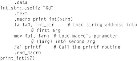
The macro has a formal parameter, $arg, that names the argument to the macro. When the macro is expanded, the argument from a call is substituted for the formal parameter throughout the macro’s body. Then the assembler replaces the call with the macro’s newly expanded body. In the first call on print_int, the argument is $7, so the macro expands to the code
la $a0, int_str
mov $a1, $7
jal printf
formal parameter
A variable that is the argument to a procedure or macro; replaced by that argument once the macro is expanded.
In a second call on print_int, say, print_int($t0), the argument is $t0, so the macro expands to
la $a0, int_str
mov $a1, $t0
jal printf
What does the call print_int($a0) expand to?
la $aO, int_str
mov $a1, $a0
jal printf
Answer
This example illustrates a drawback of macros. A programmer who uses this macro must be aware that print_int uses register $a0 and so cannot correctly print the value in that register.
Hardware/Software Interface
Some assemblers also implement pseudoinstructions, which are instructions provided by an assembler but not implemented in hardware. Chapter 2 contains many examples of how the MIPS assembler synthesizes pseudoinstructions and addressing modes from the spartan MIPS hardware instruction set. For example, Section 2.7 in Chapter 2 describes how the assembler synthesizes the blt instruc tion from two other instructions: slt and bne. By extending the instruction set, the MIPS assembler makes assembly language programming easier without complicating the hardware. Many pseudoinstructions could also be simulated with macros, but the MIPS assembler can generate better code for these instructions because it can use a dedicated register ($at) and is able to optimize the generated code.
Elaboration
Assemblers conditionally assemble pieces of code, which permits a programmer to include or exclude groups of instructions when a program is assembled. This feature is particularly useful when several versions of a program differ by a small amount. Rather than keep these programs in separate files—which greatly complicates fixing bugs in the common code—programmers typically merge the versions into a single file. Code particular to one version is conditionally assembled, so it can be excluded when other versions of the program are assembled.
If macros and conditional assembly are useful, why do assemblers for UNIX systems rarely, if ever, provide them? One reason is that most programmers on these systems write programs in higher-level languages like C. Most of the assembly code is produced by compilers, which find it more convenient to repeat code rather than define macros. Another reason is that other tools on UNIX—such as cpp, the C preprocessor, or m4, a general macro processor—can provide macros and conditional assembly for assembly language programs.
A.3 Linkers
Separate compilation permits a program to be split into pieces that are stored in different files. Each file contains a logically related collection of subroutines and data structures that form a module in a larger program. A file can be compiled and assembled independently of other files, so changes to one module do not require recompiling the entire program. As we discussed above, separate compilation necessitates the additional step of linking to combine object files from separate modules and fx their unresolved references.
separate compilation
Split ting a program across many files, each of which can be compiled without knowledge of what is in the other files.
The tool that merges these files is the linker (see Figure A.3.1). It performs three tasks:
■ Searches the program libraries to fnd library routines used by the program
■ Determines the memory locations that code from each module will occupy and relocates its instructions by adjusting absolute references
■ Resolves references among files
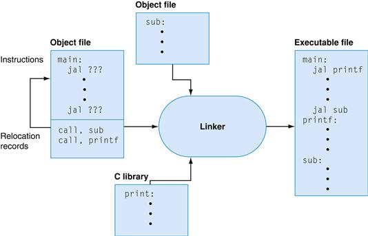
FIGURE A.3.1 The linker searches a collection of object files and program libraries to find nonlocal routines used in a program, combines them into a single executable file, and resolves references between routines in different files.
A linker’s first task is to ensure that a program contains no undefined labels. The linker matches the external symbols and unresolved references from a program’s files. An external symbol in one file resolves a reference from another file if both refer to a label with the same name. Unmatched references mean a symbol was used but not defined anywhere in the program.
Unresolved references at this stage in the linking process do not necessarily mean a programmer made a mistake. The program could have referenced a library routine whose code was not in the object files passed to the linker. After matching symbols in the program, the linker searches the system’s program libraries to find predefined subroutines and data structures that the program references. The basic libraries contain routines that read and write data, allocate and deallocate memory, and perform numeric operations. Other libraries contain routines to access a database or manipulate terminal windows. A program that references an unresolved symbol that is not in any library is erroneous and cannot be linked. When the program uses a library routine, the linker extracts the routine’s code from the library and incorporates it into the program text segment. This new routine, in turn, may depend on other library routines, so the linker continues to fetch other library routines until no external references are unresolved or a routine cannot be found.
If all external references are resolved, the linker next determines the memory locations that each module will occupy. Since the files were assembled in isolation, the assembler could not know where a module’s instructions or data would be placed relative to other modules. When the linker places a module in memory, all absolute references must be relocated to reflect its true location. Since the linker has relocation information that identifies all relocatable references, it can efficiently find and backpatch these references.
The linker produces an executable file that can run on a computer. Typically, this file has the same format as an object file, except that it contains no unresolved references or relocation information.
A.4 Loading
A program that links without an error can be run. Before being run, the program resides in a file on secondary storage, such as a disk. On UNIX systems, the operating system kernel brings a program into memory and starts it running. To start a program, the operating system performs the following steps:
1. It reads the executable file’s header to determine the size of the text and data segments.
2. It creates a new address space for the program. This address space is large enough to hold the text and data segments, along with a stack segment (see Section A.5).
3. It copies instructions and data from the executable file into the new address space.
4. It copies arguments passed to the program onto the stack.
5. It initializes the machine registers. In general, most registers are cleared, but the stack pointer must be assigned the address of the first free stack location (see Section A.5).
6. It jumps to a start-up routine that copies the program’s arguments from the stack to registers and calls the program’s main routine. If the main routine returns, the start-up routine terminates the program with the exit system call.
A.5 Memory Usage
The next few sections elaborate the description of the MIPS architecture presented earlier in the book. Earlier chapters focused primarily on hardware and its relationship with low-level software. These sections focus primarily on how assembly language programmers use MIPS hardware. These sections describe a set of conventions followed on many MIPS systems. For the most part, the hardware does not impose these conventions. Instead, they represent an agreement among programmers to follow the same set of rules so that software written by different people can work together and make effective use of MIPS hardware.
Systems based on MIPS processors typically divide memory into three parts (see Figure A.5.1). The first part, near the bottom of the address space (starting at address 400000hex), is the text segment, which holds the program’s instructions.
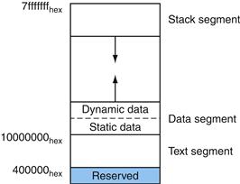
FIGURE A.5.1 Layout of memory.
The second part, above the text segment, is the data segment, which is further divided into two parts. Static data (starting at address 10000000hex) contains objects whose size is known to the compiler and whose lifetime—the interval during which a program can access them—is the program’s entire execution. For example, in C, global variables are statically allocated, since they can be referenced anytime during a program’s execution. The linker both assigns static objects to locations in the data segment and resolves references to these objects.
static data
The portion of memory that contains data whose size is known to the compiler and whose lifetime is the program’s entire execution.
Immediately above static data is dynamic data. This data, as its name implies, is allocated by the program as it executes. In C programs, the malloc library routine finds and returns a new block of memory. Since a compiler cannot predict how much memory a program will allocate, the operating system expands the dynamic data area to meet demand. As the upward arrow in the figure indicates, malloc expands the dynamic area with the sbrk system call, which causes the operating system to add more pages to the program’s virtual address space (see Section 5.4 in Chapter 5) immediately above the dynamic data segment.
Hardware/Software Interface
Because the data segment begins far above the program at address 10000000hex, load and store instructions cannot directly reference data objects with their 16-bit offset fields (see Section 2.5 in Chapter 2). For example, to load the word in the data segment at address 10010020hex into register $vO requires two instructions:
lui $s0, 0x1001 # 0x1001 means 1001 base 16
lw $v0, 0x0020($s0) # 0x10010000 + 0x0020 = 0x10010020
(The 0x before a number means that it is a hexadecimal value. For example, 0x8000 is 8000hex or 32,768ten.)
To avoid repeating the lui instruction at every load and store, MIPS systems typically dedicate a register ($gp) as a global pointer to the static data segment. This register contains address 10008000hex, so load and store instructions can use their signed 16-bit offset fields to access the first 64 KB of the static data segment. With this global pointer, we can rewrite the example as a single instruction:
lw $v0, 0x8020($gp)
Of course, a global pointer register makes addressing locations 10000000hex–10010000hex faster than other heap locations. The MIPS compiler usually stores global variables in this area, because these variables have fxed locations and ft better than other global data, such as arrays.
The third part, the program stack segment, resides at the top of the virtual address space (starting at address 7fffffffhex). Like dynamic data, the maximum size of a program’s stack is not known in advance. As the program pushes values on to the stack, the operating system expands the stack segment down toward the data segment.
stack segment
The portion of memory used by a program to hold procedure call frames.
This three-part division of memory is not the only possible one. However, it has two important characteristics: the two dynamically expandable segments are as far apart as possible, and they can grow to use a program’s entire address space.
A.6 Procedure Call Convention
Conventions governing the use of registers are necessary when procedures in a program are compiled separately. To compile a particular procedure, a compiler must know which registers it may use and which registers are reserved for other procedures. Rules for using registers are called register use or procedure call conventions. As the name implies, these rules are, for the most part, conventions followed by software rather than rules enforced by hardware. However, most compilers and programmers try very hard to follow these conventions because violating them causes insidious bugs.
register use convention
Also called procedure call convention. A software protocol governing the use of registers by procedures.
The calling convention described in this section is the one used by the gcc compiler. The native MIPS compiler uses a more complex convention that is slightly faster.
The MIPS CPU contains 32 general-purpose registers that are numbered 0–31. Register $0 always contains the hardwired value 0.
■ Registers $at (1), $k0 (26), and $k1 (27) are reserved for the assembler and operating system and should not be used by user programs or compilers.
■ Registers $a0–$a3 (4–7) are used to pass the first four arguments to routines (remaining arguments are passed on the stack). Registers $v0 and $v1 (2, 3) are used to return values from functions.
■ Registers $t0–$t9 (8–15, 24, 25) are caller-saved registers that are used to hold temporary quantities that need not be preserved across calls (see Section 2.8 in Chapter 2).
■ Registers $s0–$s7 (16–23) are callee-saved registers that hold long-lived values that should be preserved across calls.
■ Register $gp (28) is a global pointer that points to the middle of a 64K block of memory in the static data segment.
■ Register $sp (29) is the stack pointer, which points to the last location on the stack. Register $fp (30) is the frame pointer. The jal instruction writes register $ra (31), the return address from a procedure call. These two registers are explained in the next section.
caller-saved register
A register saved by the routine being called.
callee-saved register
A register saved by the routine making a procedure call.
The two-letter abbreviations and names for these registers—for example $sp for the stack pointer—reflect the registers’ intended uses in the procedure call convention. In describing this convention, we will use the names instead of register numbers. Figure A.6.1 lists the registers and describes their intended uses.
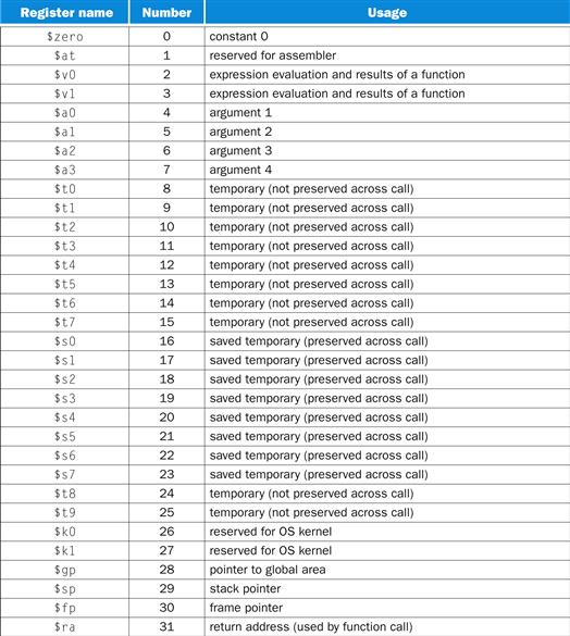
FIGURE A.6.1 MIPS registers and usage convention.
Procedure Calls
This section describes the steps that occur when one procedure (the caller) invokes another procedure (the callee). Programmers who write in a high-level language (like C or Pascal) never see the details of how one procedure calls another, because the compiler takes care of this low-level bookkeeping. However, assembly language programmers must explicitly implement every procedure call and return.
Most of the bookkeeping associated with a call is centered around a block of memory called a procedure call frame. This memory is used for a variety of purposes:
■ To hold values passed to a procedure as arguments
■ To save registers that a procedure may modify, but which the procedure’s caller does not want changed
■ To provide space for variables local to a procedure
procedure call frame
A block of memory that is used to hold values passed to a procedure as arguments, to save registers that a procedure may modify but that the procedure’s caller does not want changed, and to provide space for variables local to a procedure.
In most programming languages, procedure calls and returns follow a strict last-in, first-out (LIFO) order, so this memory can be allocated and deallocated on a stack, which is why these blocks of memory are sometimes called stack frames.
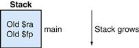
Figure A.6.2 shows a typical stack frame. The frame consists of the memory between the frame pointer ($fp), which points to the first word of the frame, and the stack pointer ($sp), which points to the last word of the frame. The stack grows down from higher memory addresses, so the frame pointer points above the stack pointer. The executing procedure uses the frame pointer to quickly access values in its stack frame. For example, an argument in the stack frame can be loaded into register $v0 with the instruction
1w $v0, 0($fp)
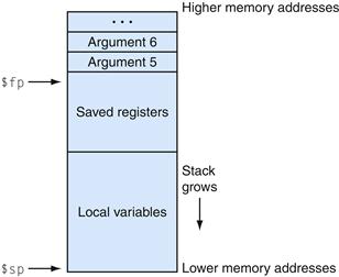
FIGURE A.6.2 Layout of a stack frame.
The frame pointer ($fp) points to the first word in the currently executing procedure’s stack frame. The stack pointer ($sp) points to the last word of the frame. The first four arguments are passed in registers, so the fifth argument is the first one stored on the stack.
A stack frame may be built in many different ways; however, the caller and callee must agree on the sequence of steps. The steps below describe the calling convention used on most MIPS machines. This convention comes into play at three points during a procedure call: immediately before the caller invokes the callee, just as the callee starts executing, and immediately before the callee returns to the caller. In the first part, the caller puts the procedure call arguments in standard places and invokes the callee to do the following:
1. Pass arguments. By convention, the first four arguments are passed in registers $a0–$a3. Any remaining arguments are pushed on the stack and appear at the beginning of the called procedure’s stack frame.
2. Save caller-saved registers. The called procedure can use these registers ($a0–$a3 and $t0–$t9) without first saving their value. If the caller expects to use one of these registers after a call, it must save its value before the call.
3. Execute a jal instruction (see Section 2.8 of Chapter 2), which jumps to the callee’s first instruction and saves the return address in register $ra.
Before a called routine starts running, it must take the following steps to set up its stack frame:
1. Allocate memory for the frame by subtracting the frame’s size from the stack pointer.
2. Save callee-saved registers in the frame. A callee must save the values in these registers ($s0–$s7, $fp, and $ra) before altering them, since the caller expects to fnd these registers unchanged after the call. Register $fp is saved by every procedure that allocates a new stack frame. However, register $ra only needs to be saved if the callee itself makes a call. The other callee-saved registers that are used also must be saved.
3. Establish the frame pointer by adding the stack frame’s size minus 4 to $sp and storing the sum in register $fp.
Hardware/Software Interface
The MIPS register use convention provides callee-and caller-saved registers, because both types of registers are advantageous in different circumstances. Callee-saved registers are better used to hold long-lived values, such as variables from a user’s program. These registers are only saved during a procedure call if the callee expects to use the register. On the other hand, caller-saved registers are better used to hold short-lived quantities that do not persist across a call, such as immediate values in an address calculation. During a call, the callee can also use these registers for short-lived temporaries.
Finally, the callee returns to the caller by executing the following steps:
1. If the callee is a function that returns a value, place the returned value in register $v0.
2. Restore all callee-saved registers that were saved upon procedure entry.
3. Pop the stack frame by adding the frame size to $sp.
4. Return by jumping to the address in register $ra.
Elaboration
A programming language that does not permit recursive procedures—procedures that call themselves either directly or indirectly through a chain of calls—need not allocate frames on a stack. In a nonrecursive language, each procedure’s frame may be statically allocated, since only one invocation of a procedure can be active at a time. Older versions of Fortran prohibited recursion, because statically allocated frames produced faster code on some older machines. However, on load store architectures like MIPS, stack frames may be just as fast, because a frame pointer register points directly to the active stack frame, which permits a single load or store instruction to access values in the frame. In addition, recursion is a valuable programming technique.
recursive procedures
Procedures that call themselves either directly or indirectly through a chain of calls.
Procedure Call Example
As an example, consider the C routine
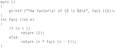
which computes and prints 10! (the factorial of 10, 10! = 10 × 9 × … × 1). fact is a recursive routine that computes n! by multiplying n times (n − 1)!. The assembly code for this routine illustrates how programs manipulate stack frames.
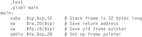
Upon entry, the routine main creates its stack frame and saves the two callee-saved registers it will modify: $fp and $ra. The frame is larger than required for these two register because the calling convention requires the minimum size of a stack frame to be 24 bytes. This minimum frame can hold four argument registers ($a0–$a3) and the return address $ra, padded to a doubleword boundary (24 bytes). Since main also needs to save $fp, its stack frame must be two words larger (remember: the stack pointer is kept doubleword aligned).
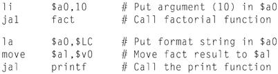
The routine main then calls the factorial routine and passes it the single argument 10. After fact returns, main calls the library routine printf and passes it both a format string and the result returned from fact:
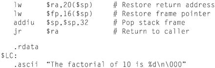
Finally, after printing the factorial, main returns. But first, it must restore the registers it saved and pop its stack frame:
The factorial routine is similar in structure to main. First, it creates a stack frame and saves the callee-saved registers it will use. In addition to saving $ra and $fp, fact also saves its argument ($a0), which it will use for the recursive call:
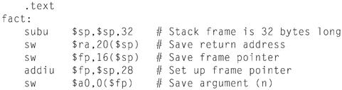
The heart of the fact routine performs the computation from the C program. It tests whether the argument is greater than 0. If not, the routine returns the value 1. If the argument is greater than 0, the routine recursively calls itself to compute fact(n-1) and multiplies that value times n:
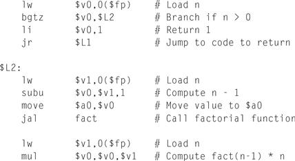
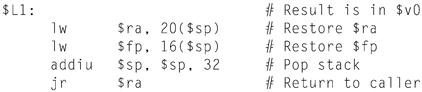
Finally, the factorial routine restores the callee-saved registers and returns the value in register $v0:
Stack in Recursive Procedure
Example
Figure A.6.3 shows the stack at the call fact(7).main runs first, so its frame is deepest on the stack. main calls fact(10), whose stack frame is next on the stack. Each invocation recursively invokes fact to compute the next-lowest factorial. The stack frames parallel the LIFO order of these calls. What does the stack look like when the call to fact(10) returns?
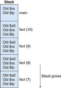
FIGURE A.6.3 Stack frames during the call of fact(7).
Answer
Elaboration
The difference between the MIPS compiler and the gcc compiler is that the MIPS compiler usually does not use a frame pointer, so this register is available as another callee-saved register, $s8. This change saves a couple of instructions in the procedure call and return sequence. However, it complicates code generation, because a procedure must access its stack frame with $sp, whose value can change during a procedure’s execution if values are pushed on the stack.
Another Procedure Call Example
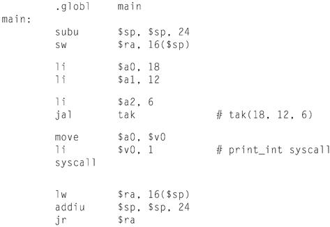
As another example, consider the following routine that computes the tak function, which is a widely used benchmark created by Ikuo Takeuchi. This function does not compute anything useful, but is a heavily recursive program that illustrates the MIPS calling convention.
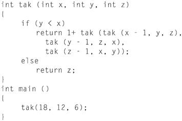
The assembly code for this program is shown below. The tak function first saves its return address in its stack frame and its arguments in callee-saved regis ters, since the routine may make calls that need to use registers $a0–$a2 and $ra. The function uses callee-saved registers, since they hold values that persist over the lifetime of the function, which includes several calls that could potentially modify registers.
The routine then begins execution by testing if y < x. If not, it branches to label L1, which is shown below.
|
bge |
$s1, $s0, L1 |
# if (y < x) |
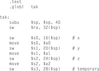
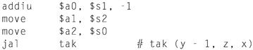
If y < x, then it executes the body of the routine, which contains four recursive calls. The first call uses almost the same arguments as its parent:
Note that the result from the first recursive call is saved in register $s3, so that it can be used later.
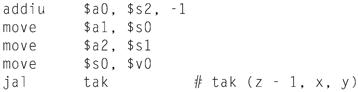
The function now prepares arguments for the second recursive call.
In the instructions below, the result from this recursive call is saved in register $s0. But first we need to read, for the last time, the saved value of the first argument from this register.
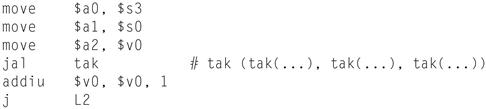
After the three inner recursive calls, we are ready for the final recursive call. After the call, the function’s result is in $v0 and control jumps to the function’s epilogue.
This code at label L1 is the consequent of the if-then-else statement. It just moves the value of argument z into the return register and falls into the function epilogue.
![]()
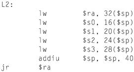
The code below is the function epilogue, which restores the saved registers and returns the function’s result to its caller.
The main routine calls the tak function with its initial arguments, then takes the computed result (7) and prints it using SPIM’s system call for printing integers.
A.7 Exceptions and Interrupts
Section 4.9 of Chapter 4 describes the MIPS exception facility, which responds both to exceptions caused by errors during an instruction’s execution and to external interrupts caused by I/O devices. This section describes exception and interrupt handling in more detail.1 In MIPS processors, a part of the CPU called coprocessor 0 records the information the software needs to handle excep tions and interrupts. The MIPS simulator SPIM does not implement all of copro cessor 0’s registers, since many are not useful in a simulator or are part of the memory system, which SPIM does not implement. However, SPIM does provide the following coprocessor 0 registers:
interrupt handler
A piece of code that is run as a result of an exception or an interrupt.
|
Register name |
Register number |
Usage |
|
BadVAddr |
8 |
memory address at which an offending memory reference occurred |
|
Count |
9 |
timer |
|
Compare |
11 |
value compared against timer that causes interrupt when they match |
|
Status |
12 |
interrupt mask and enable bits |
|
Cause |
13 |
exception type and pending interrupt bits |
|
EPC |
14 |
address of instruction that caused exception |
|
Confg |
16 |
confguration of machine |
These seven registers are part of coprocessor 0’s register set. They are accessed by the mfcO and mtcO instructions. After an exception, register EPC contains the address of the instruction that was executing when the exception occurred. If the exception was caused by an external interrupt, then the instruction will not have started executing. All other exceptions are caused by the execution of the instruc tion at EPC, except when the offending instruction is in the delay slot of a branch or jump. In that case, EPC points to the branch or jump instruction and the BD bit is set in the Cause register. When that bit is set, the exception handler must look at EPC + 4 for the offending instruction. However, in either case, an excep tion handler properly resumes the program by returning to the instruction at EPC.
If the instruction that caused the exception made a memory access, register BadVAddr contains the referenced memory location’s address.
The Count register is a timer that increments at a fxed rate (by default, every 10 milliseconds) while SPIM is running. When the value in the Count register equals the value in the Compare register, a hardware interrupt at priority level 5 occurs.
Figure A.7.1 shows the subset of the Status register fields implemented by the MIPS simulator SPIM. The interrupt mask field contains a bit for each of the six hardware and two software interrupt levels. A mask bit that is 1 allows interrupts at that level to interrupt the processor. A mask bit that is 0 disables interrupts at that level. When an interrupt arrives, it sets its interrupt pending bit in the Cause register, even if the mask bit is disabled. When an interrupt is pending, it will interrupt the processor when its mask bit is subsequently enabled.
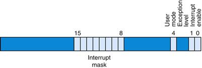
FIGURE A.7.1 The Status register.
The user mode bit is 0 if the processor is running in kernel mode and 1 if it is running in user mode. On SPIM, this bit is fxed at 1, since the SPIM processor does not implement kernel mode. The exception level bit is normally 0, but is set to 1 after an exception occurs. When this bit is 1, interrupts are disabled and the EPC is not updated if another exception occurs. This bit prevents an exception handler from being disturbed by an interrupt or exception, but it should be reset when the handler fnishes. If the interrupt enable bit is 1, interrupts are allowed. If it is 0, they are disabled.
Figure A.7.2 shows the subset of Cause register fields that SPIM implements. The branch delay bit is 1 if the last exception occurred in an instruction executed in the delay slot of a branch. The interrupt pending bits become 1 when an interrupt is raised at a given hardware or software level. The exception code register describes the cause of an exception through the following codes:
|
Number |
Name |
Cause of exception |
|
0 |
Int |
interrupt (hardware) |
|
4 |
AdEL |
address error exception (load or instruction fetch) |
|
5 |
AdES |
address error exception (store) |
|
6 |
BE |
bus error on instruction fetch |
|
7 |
DBE |
bus error on data load or store |
|
8 |
Sys |
syscall exception |
|
9 |
Bp |
breakpoint exception |
|
10 |
RI |
reserved instruction exception |
|
11 |
CpU |
coprocessor unimplemented |
|
12 |
Ov |
arithmetic overflow exception |
|
13 |
Tr |
trap |
|
15 |
FPE |
floating point |
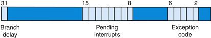
FIGURE A.7.2 The Cause register.
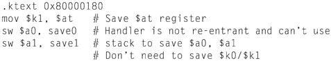
Exceptions and interrupts cause a MIPS processor to jump to a piece of code, at address 80000180hex (in the kernel, not user address space), called an exception handler. This code examines the exception’s cause and jumps to an appropriate point in the operating system. The operating system responds to an exception either by terminating the process that caused the exception or by performing some action. A process that causes an error, such as executing an unimplemented instruction, is killed by the operating system. On the other hand, other exceptions such as page faults are requests from a process to the operating system to perform a service, such as bringing in a page from disk. The operating system processes these requests and resumes the process. The final type of exceptions are interrupts from external devices. These generally cause the operating system to move data to or from an I/O device and resume the interrupted process.
The code in the example below is a simple exception handler, which invokes a routine to print a message at each exception (but not interrupts). This code is similar to the exception handler (exceptions.s) used by the SPIM simulator.
Exception Handler
Example
The exception handler first saves register $at, which is used in pseudoinstructions in the handler code, then saves $a0 and $a1, which it later uses to pass arguments. The exception handler cannot store the old values from these registers on the stack, as would an ordinary routine, because the cause of the exception might have been a memory reference that used a bad value (such as 0) in the stack pointer. Instead, the exception handler stores these registers in an exception handler register ($k1, since it can’t access memory without using $at) and two memory locations (save0 and save1). If the exception routine itself could be interrupted, two locations would not be enough since the second exception would overwrite values saved during the first exception. However, this simple exception handler fnishes running before it enables interrupts, so the problem does not arise.
The exception handler then moves the Cause and EPC registers into CPU registers. The Cause and EPC registers are not part of the CPU register set. In stead, they are registers in coprocessor 0, which is the part of the CPU that handles exceptions. The instruction mfcO $k0, $13 moves coprocessor 0’s register 13 (the Cause register) into CPU register $k0. Note that the exception handler need not save registers $k0 and $k1, because user programs are not supposed to use these registers. The exception handler uses the value from the Cause reg ister to test whether the exception was caused by an interrupt (see the preceding ta ble). If so, the exception is ignored. If the exception was not an interrupt, the handler calls print_excp to print a message.
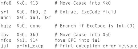
Before returning, the exception handler clears the Cause register; resets the Status register to enable interrupts and clear the EXL bit, which allows subse quent exceptions to change the EPC register; and restores registers $a0, $a1, and $at. It then executes the eret (exception return) instruction, which returns to the instruction pointed to by EPC. This exception handler returns to the instruction following the one that caused the exception, so as to not re-execute the faulting instruction and cause the same exception again.
Elaboration
On real MIPS processors, the return from an exception handler is more complex. The exception handler cannot always jump to the instruction following EPC. For example, if the instruction that caused the exception was in a branch instruction’s delay slot (see Chapter 4), the next instruction to execute may not be the following instruction in memory.
A.8 Input and Output
SPIM simulates one I/O device: a memory-mapped console on which a program can read and write characters. When a program is running, SPIM connects its own terminal (or a separate console window in the X-window version xspim or the Windows version PCSpim) to the processor. A MIPS program running on SPIM can read the characters that you type. In addition, if the MIPS program writes characters to the terminal, they appear on SPIM’s terminal or console window. One exception to this rule is control-C: this character is not passed to the program, but instead causes SPIM to stop and return to command mode. When the program stops running (for example, because you typed control-C or because the program hit a breakpoint), the terminal is reconnected to SPIM so you can type SPIM commands.
To use memory-mapped I/O (see below), spim or xspim must be started with the -mapped_io flag. PCSpim can enable memory-mapped I/O through a command line flag or the “Settings” dialog.
The terminal device consists of two independent units: a receiver and a transmitter. The receiver reads characters from the keyboard. The transmitter displays characters on the console. The two units are completely independent. This means, for example, that characters typed at the keyboard are not automatically echoed on the display. Instead, a program echoes a character by reading it from the receiver and writing it to the transmitter.
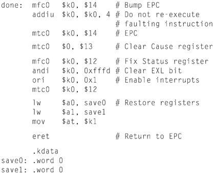
A program controls the terminal with four memory-mapped device registers, as shown in Figure A.8.1. “Memory-mapped” means that each register appears as a special memory location. The Receiver Control register is at location ffff0000hex. Only two of its bits are actually used. Bit 0 is called “ready”: if it is 1, it means that a character has arrived from the keyboard but has not yet been read from the Receiver Data register. The ready bit is read-only: writes to it are ignored. The ready bit changes from 0 to 1 when a character is typed at the keyboard, and it changes from 1 to 0 when the character is read from the Receiver Data register.
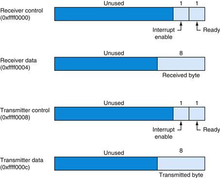
FIGURE A.8.1 The terminal is controlled by four device registers, each of which appears as a memory location at the given address.
Only a few bits of these registers are actually used. The others always read as 0s and are ignored on writes.
Bit 1 of the Receiver Control register is the keyboard “interrupt enable.” This bit may be both read and written by a program. The interrupt enable is initially 0. If it is set to 1 by a program, the terminal requests an interrupt at hardware level 1 whenever a character is typed, and the ready bit becomes 1. However, for the interrupt to affect the processor, interrupts must also be enabled in the Status register (see Section A.7). All other bits of the Receiver Control register are unused.
The second terminal device register is the Receiver Data register (at address ffff0004hex). The low-order eight bits of this register contain the last character typed at the keyboard. All other bits contain 0s. This register is read-only and changes only when a new character is typed at the keyboard. Reading the Receiver Data register resets the ready bit in the Receiver Control register to 0. The value in this register is undefined if the Receiver Control register is 0.
The third terminal device register is the Transmitter Control register (at address ffff0008hex). Only the low-order two bits of this register are used. They behave much like the corresponding bits of the Receiver Control register. Bit 0 is called “ready” and is read-only. If this bit is 1, the transmitter is ready to accept a new character for output. If it is 0, the transmitter is still busy writing the previous character. Bit 1 is “interrupt enable” and is readable and writable. If this bit is set to 1, then the terminal requests an interrupt at hardware level 0 whenever the transmitter is ready for a new character, and the ready bit becomes 1.
The final device register is the Transmitter Data register (at address ffff000chex). When a value is written into this location, its low-order eight bits (i.e., an ASCII character as in Figure 2.15 in Chapter 2) are sent to the console. When the Transmitter Data register is written, the ready bit in the Transmitter Control register is reset to 0. This bit stays 0 until enough time has elapsed to transmit the character to the terminal; then the ready bit becomes 1 again. The Trans mitter Data register should only be written when the ready bit of the Transmitter Control register is 1. If the transmitter is not ready, writes to the Transmitter Data register are ignored (the write appears to succeed but the character is not output).
Real computers require time to send characters to a console or terminal. These time lags are simulated by SPIM. For example, after the transmitter starts to write a character, the transmitter’s ready bit becomes 0 for a while. SPIM measures time in instructions executed, not in real clock time. This means that the transmitter does not become ready again until the processor executes a fxed number of instructions. If you stop the machine and look at the ready bit, it will not change. However, if you let the machine run, the bit eventually changes back to 1.
A.9 SPIM
SPIM is a software simulator that runs assembly language programs written for processors that implement the MIPS-32 architecture, specifcally Release 1 of this architecture with a fxed memory mapping, no caches, and only coprocessors 0 and 1.2 SPIM’s name is just MIPS spelled backwards. SPIM can read and immediately execute assembly language files. SPIM is a self-contained system for running MIPS programs. It contains a debugger and provides a few operating system–like services. SPIM is much slower than a real computer (100 or more times). How ever, its low cost and wide availability cannot be matched by real hardware!
An obvious question is, “Why use a simulator when most people have PCs that contain processors that run signifcantly faster than SPIM?” One reason is that the processor in PCs are Intel 80x86s, whose architecture is far less regular and far more complex to understand and program than MIPS processors. The MIPS architecture may be the epitome of a simple, clean RISC machine.
In addition, simulators can provide a better environment for assembly programming than an actual machine because they can detect more errors and provide a better interface than an actual computer.
Finally, simulators are useful tools in studying computers and the programs that run on them. Because they are implemented in software, not silicon, simulators can be examined and easily modifed to add new instructions, build new systems such as multiprocessors, or simply collect data.
Simulation of a Virtual Machine
The basic MIPS architecture is diffcult to program directly because of delayed branches, delayed loads, and restricted address modes. This diffculty is tolerable since these computers were designed to be programmed in high-level languages and present an interface designed for compilers rather than assembly language programmers. A good part of the programming complexity results from delayed instructions. A delayed branch requires two cycles to execute (see the Elaborations on pages 343 and 381 of Chapter 4). In the second cycle, the instruction immediately following the branch executes. This instruction can perform useful work that normally would have been done before the branch. It can also be a nop (no operation) that does nothing. Similarly, delayed loads require two cycles to bring a value from memory, so the instruction immediately following a load cannot use the value (see Section 4.2 of Chapter 4).
MIPS wisely chose to hide this complexity by having its assembler implement a virtual machine. This virtual computer appears to have nondelayed branches and loads and a richer instruction set than the actual hardware. The assembler reorganizes (rearranges) instructions to fll the delay slots. The virtual computer also provides pseudoinstructions, which appear as real instructions in assembly lan guage programs. The hardware, however, knows nothing about pseudoinstructions, so the assembler must translate them into equivalent sequences of actual machine instructions. For example, the MIPS hardware only provides instructions to branch when a register is equal to or not equal to 0. Other conditional branches, such as one that branches when one register is greater than another, are synthesized by comparing the two registers and branching when the result of the comparison is true (nonzero).
virtual machine
A virtual computer that appears to have nondelayed branches and loads and a richer instruction set than the actual hardware.
By default, SPIM simulates the richer virtual machine, since this is the machine that most programmers will find useful. However, SPIM can also simulate the delayed branches and loads in the actual hardware. Below, we describe the virtual machine and only mention in passing features that do not belong to the actual hardware. In doing so, we follow the convention of MIPS assembly language programmers (and compilers), who routinely use the extended machine as if it was implemented in silicon.
Getting Started with SPIM
The rest of this appendix introduces SPIM and the MIPS R2000 Assembly language. Many details should never concern you; however, the sheer volume of information can sometimes obscure the fact that SPIM is a simple, easy-to-use program. This section starts with a quick tutorial on using SPIM, which should enable you to load, debug, and run simple MIPS programs.
SPIM comes in different versions for different types of computer systems. The one constant is the simplest version, called spim, which is a command-line-driven program that runs in a console window. It operates like most programs of this type: you type a line of text, hit the return key, and spim executes your command. Despite its lack of a fancy interface, spim can do everything that its fancy cousins can do.
There are two fancy cousins to spim. The version that runs in the X-windows environment of a UNIX or Linux system is called xspim. xspim is an easier program to learn and use than spim, because its commands are always visible on the screen and because it continually displays the machine’s registers and memory. The other fancy version is called PCspim and runs on Microsoft Windows. The UNIX and Windows versions of SPIM ![]() are on the CD (click on Tutorials). Tutorials on xspim, pcSpim, spim, and SPIM command-line options
are on the CD (click on Tutorials). Tutorials on xspim, pcSpim, spim, and SPIM command-line options ![]() are on the CD (click on Software).
are on the CD (click on Software).
If you are going to run SPIM on a PC running Microsoft Windows, you should first look at the tutorial on PCSpim ![]() on the CD. If you are going to run SPIM on a computer running UNIX or Linux, you should read the tutorial on xspim
on the CD. If you are going to run SPIM on a computer running UNIX or Linux, you should read the tutorial on xspim ![]() (click on Tutorials).
(click on Tutorials).
Surprising Features
Although SPIM faithfully simulates the MIPS computer, SPIM is a simulator, and certain things are not identical to an actual computer. The most obvious differences are that instruction timing and the memory systems are not identical. SPIM does not simulate caches or memory latency, nor does it accurately refect floating-point operation or multiply and divide instruction delays. In addition, the floating-point instructions do not detect many error conditions, which would cause exceptions on a real machine.
Another surprise (which occurs on the real machine as well) is that a pseudoinstruction expands to several machine instructions. When you single-step or examine memory, the instructions that you see are different from the source program. The correspondence between the two sets of instructions is fairly simple, since SPIM does not reorganize instructions to fll delay slots.
Byte Order
Processors can number bytes within a word so the byte with the lowest number is either the leftmost or rightmost one. The convention used by a machine is called its byte order. MIPS processors can operate with either big-endian or little-endian byte order. For example, in a big-endian machine, the directive .byte 0, 1, 2, 3 would result in a memory word containing
![]()
while in a little-endian machine, the word would contain
![]()
SPIM operates with both byte orders. SPIM’s byte order is the same as the byte order of the underlying machine that runs the simulator. For example, on an Intel 80 × 86, SPIM is little-endian, while on a Macintosh or Sun SPARC, SPIM is big-endian.
System Calls
SPIM provides a small set of operating system-like services through the system call (syscall) instruction. To request a service, a program loads the system call code (see Figure A.9.1) into register $v0 and arguments into registers $a0–$a3 (or $f12 for floating-point values). System calls that return values put their results in register $v0 (or $f0 for floating-point results). For example, the follow ing code prints “the answer = 5”:
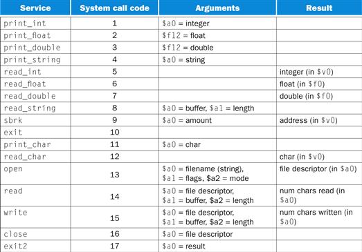
FIGURE A.9.1 System services.
The print_int system call is passed an integer and prints it on the console. print_float prints a single floating-point number; print_double prints a double precision number; and print_string is passed a pointer to a null-terminated string, which it writes to the console.
The system calls read_int, read_float, and read_double to read an entire line of input up to and including the newline. Characters following the number are ignored. read_string has the same semantics as the UNIX library routine fgets. It reads up to n − 1 characters into a buffer and terminates the string with a null byte. If fewer than n − 1 characters are on the current line, read_string reads up to and including the newline and again null-terminates the string. Warning: Programs that use these syscalls to read from the terminal should not use memory-mapped I/O (see Section A.8).
sbrk returns a pointer to a block of memory containing n additional bytes. exit stops the program SPIM is running. exit2 terminates the SPIM program, and the argument to exit2 becomes the value returned when the SPIM simulator itself terminates.
print_char and read_char write and read a single character. open, read, write, and close are the standard UNIX library calls.
A.10 MIPS R2000 Assembly Language
A MIPS processor consists of an integer processing unit (the CPU) and a collection of coprocessors that perform ancillary tasks or operate on other types of data, such as floating-point numbers (see Figure A.10.1). SPIM simulates two coproces sors. Coprocessor 0 handles exceptions and interrupts. Coprocessor 1 is the floating-point unit. SPIM simulates most aspects of this unit.
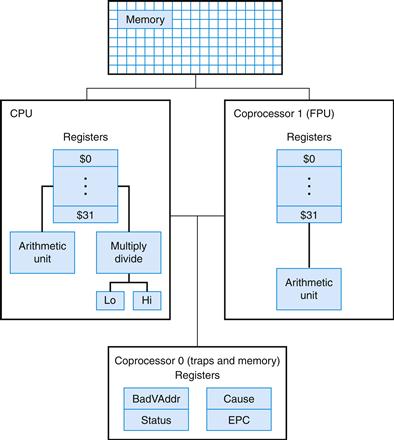
FIGURE A.10.1 MIPS R2000 CPU and FPU.
Addressing Modes
MIPS is a load store architecture, which means that only load and store instruc tions access memory. Computation instructions operate only on values in registers. The bare machine provides only one memory-addressing mode: c(rx), which uses the sum of the immediate c and register rx as the address. The virtual machine provides the following addressing modes for load and store instructions:
|
Format |
Address computation |
|
(register) |
contents of register |
|
imm |
immediate |
|
imm (register) |
immediate + contents of register |
|
label |
address of label |
|
label ± imm |
address of label + or − immediate |
|
label ± imm (register) |
address of label + or − (immediate + contents of register) |
Most load and store instructions operate only on aligned data. A quantity is aligned if its memory address is a multiple of its size in bytes. Therefore, a halfword object must be stored at even addresses, and a full word object must be stored at addresses that are a multiple of four. However, MIPS provides some instructions to manipulate unaligned data (lwl, lwr, swl, and swr).
Elaboration
The MIPS assembler (and SPIM) synthesizes the more complex addressing modes by producing one or more instructions before the load or store to compute a complex address. For example, suppose that the label table referred to memory location 0x10000004 and a program contained the instruction
ld $a0, table + 4($al)
The assembler would translate this instruction into the instructions
lui $at, 4096
addu $at, $at, $al
lw $a0, 8($at)
The first instruction loads the upper bits of the label’s address into register $at, which is the register that the assembler reserves for its own use. The second instruction adds the contents of register $a1 to the label’s partial address. Finally, the load instruction uses the hardware address mode to add the sum of the lower bits of the label’s address and the offset from the original instruction to the value in register $at.
Assembler Syntax
Comments in assembler files begin with a sharp sign (#). Everything from the sharp sign to the end of the line is ignored.
Identifers are a sequence of alphanumeric characters, underbars (_), and dots (.) that do not begin with a number. Instruction opcodes are reserved words that cannot be used as identifers. Labels are declared by putting them at the beginning of a line followed by a colon, for example:
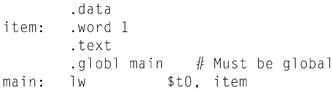
Numbers are base 10 by default. If they are preceded by 0x, they are interpreted as hexadecimal. Hence, 256 and 0x100 denote the same value.
Strings are enclosed in double quotes (”). Special characters in strings follow the C convention:
■ newline \n
■ tab \t
■ quote \”
SPIM supports a subset of the MIPS assembler directives:
|
.align n |
Align the next datum on a 2n byte boundary. For example, .align 2 aligns the next value on a word boundary. .align 0 turns off automatic alignment of .half, .word, .float, and .double directives until the next .data or .kdata directive. |
|
.ascii str |
Store the string str in memory, but do not null-terminate it. |
|
.asciiz str |
Store the string str in memory and null-terminate it. |
|
.byte bl,..., bn |
Store the n values in successive bytes of memory. |
|
.data <addr> |
Subsequent items are stored in the data segment. If the optional argument addr is present, subsequent items are stored starting at address addr. |
|
.double d1,..., dn |
Store the n floating-point double precision numbers in successive memory locations. |
|
.extern sym size |
Declare that the datum stored at sym is size bytes large and is a global label. This directive enables the assembler to store the datum in a portion of the data segment that is effciently accessed via register $gp. |
|
.float fl,..., fn |
Store the n floating-point single precision numbers in successive memory locations. |
|
.globl sym |
Declare that label sym is global and can be referenced from other files. |
|
.half h1,..., hn |
Store the n 16-bit quantities in successive mem ory halfwords. |
|
.kdata <addr> |
Subsequent data items are stored in the kernel data segment. If the optional argument addr is present, subsequent items are stored starting at address addr. |
|
.ktext <addr> |
Subsequent items are put in the kernel text segment. In SPIM, these items may only be instructions or words (see the .word directive below). If the optional argument addr is present, subse quent items are stored starting at address addr. |
|
.set noat and .set at |
The first directive prevents SPIM from complaining about subsequent instructions that use register $at. The second directive re-enables the warning. Since pseudoinstructions expand into code that uses register $at, programmers must be very careful about leaving values in this register. |
|
.space n |
Allocates n bytes of space in the current segment (which must be the data segment in SPIM). |
|
.text <addr> |
Subsequent items are put in the user text segment. In SPIM, these items may only be instruc tions or words (see the .word directive below). If the optional argument addr is present, subse quent items are stored starting at address addr. |
|
.word w1,..., wn |
Store the n 32-bit quantities in successive memory words. |
SPIM does not distinguish various parts of the data segment (.data, .rdata, and .sdata).
Encoding MIPS Instructions
Figure A.10.2 explains how a MIPS instruction is encoded in a binary number. Each column contains instruction encodings for a field (a contiguous group of bits) from an instruction. The numbers at the left margin are values for a field. For example, the j opcode has a value of 2 in the opcode field. The text at the top of a column names a field and specifes which bits it occupies in an instruction. For example, the op field is contained in bits 26–31 of an instruction. This field encodes most instructions. However, some groups of instructions use additional fields to distinguish related instructions. For example, the different floating-point instructions are specifed by bits 0–5. The arrows from the first column show which opcodes use these additional fields.
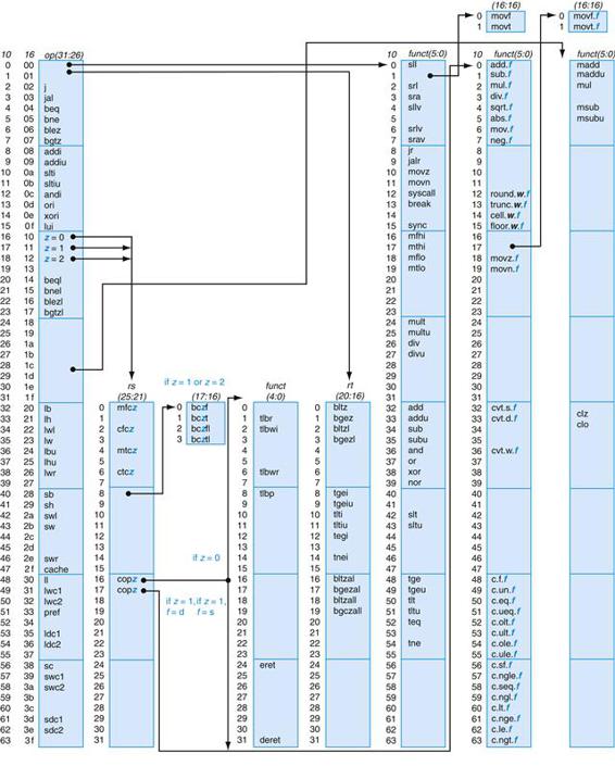
FIGURE A.10.2 MIPS opcode map.
The values of each field are shown to its left. The first column shows the values in base 10, and the second shows base 16 for the op field (bits 31 to 26) in the third column. This op field completely specifies the MIPS operation except for six op values: 0, 1, 16, 17, 18, and 19. These operations are determined by other fields, identified by pointers. The last field (funct) uses “f” to mean “s” if rs = 16 and op = 17 or “d” if rs = 17 and op = 17. The second field (rs) uses “z” to mean “0”, “1”, “2”, or “3” if op = 16, 17, 18, or 19, respectively. If rs = 16, the operation is specified elsewhere: if z = 0, the operations are specified in the fourth field (bits 4 to 0); if z = 1, then the operations are in the last field with f = s. If rs = 17 and z = 1, then the operations are in the last field with f = d.
Instruction Format
The rest of this appendix describes both the instructions implemented by actual MIPS hardware and the pseudoinstructions provided by the MIPS assembler. The two types of instructions are easily distinguished. Actual instructions depict the fields in their binary representation. For example, in
Addition (with overflow)
![]()
the add instruction consists of six fields. Each field’s size in bits is the small num ber below the field. This instruction begins with six bits of 0s. Register specifers begin with an r, so the next field is a 5-bit register specifer called rs. This is the same register that is the second argument in the symbolic assembly at the left of this line. Another common field is imm16, which is a 16-bit immediate number.
Pseudoinstructions follow roughly the same conventions, but omit instruction encoding information. For example:
Multiply (without overflow)
|
mill rdest, rsrc1, src2 |
pseudoinstruction |
In pseudoinstructions, rdest and rsrc1 are registers and src2 is either a register or an immediate value. In general, the assembler and SPIM translate a more general form of an instruction (e.g., add $v1, $a0, 0x55) to a specialized form (e.g., addi $v1, $a0, 0x55).
Arithmetic and Logical Instructions
Absolute value
|
abs rdest, rsrc |
pseudoinstruction |
Put the absolute value of register rsrc in register rdest.
Addition (with overflow)
![]()
Addition (without overflow)
![]()
Put the sum of registers rs and rt into register rd.
Addition immediate (with overflow)
![]()
Addition immediate (without overflow)
![]()
Put the sum of register rs and the sign-extended immediate into register rt.
AND
![]()
Put the logical AND of registers rs and rt into register rd.
AND immediate
![]()
Put the logical AND of register rs and the zero-extended immediate into register rt.
Count leading ones
![]()
Count leading zeros
![]()
Count the number of leading ones (zeros) in the word in register rs and put the result into register rd. If a word is all ones (zeros), the result is 32.
Divide (with overflow)
![]()
Divide (without overflow)
![]()
Divide register rs by register rt. Leave the quotient in register lo and the remainder in register hi. Note that if an operand is negative, the remainder is unspecifed by the MIPS architecture and depends on the convention of the machine on which SPIM is run.
Divide (with overflow)
|
div rdest, rsrc1, src2 |
pseudoinstruction |
Divide (without overflow)
|
divu rdest, rsrc1, src2 |
pseudoinstruction |
Put the quotient of register rsrc1 and src2 into register rdest.
Multiply
![]()
Unsigned multiply
![]()
Multiply registers rs and rt. Leave the low-order word of the product in register lo and the high-order word in register hi.
Multiply (without overflow)
![]()
Put the low-order 32 bits of the product of rs and rt into register rd.
Multiply (with overflow)
|
mulo rdest, rsrc1, src2 |
pseudoinstruction |
Unsigned multiply (with overflow)
|
mulou rdest, rsrc1, src2 |
pseudoinstruction |
Put the low-order 32 bits of the product of register rsrc1 and src2 into register rdest.
Multiply add
![]()
Unsigned multiply add
![]()
Multiply registers rs and rt and add the resulting 64-bit product to the 64-bit value in the concatenated registers lo and hi.
Multiply subtract
![]()
Unsigned multiply subtract
![]()
Multiply registers rs and rt and subtract the resulting 64-bit product from the 64-bit value in the concatenated registers lo and hi.
Negate value (with overflow)
|
neg rdest, rsrc |
pseudoinstruction |
Negate value (without overflow)
|
negu rdest, rsrc |
pseudoinstruction |
Put the negative of register rsrc into register rdest.
NOR
![]()
Put the logical NOR of registers rs and rt into register rd.
NOT
|
not rdest, rsrc |
pseudoinstruction |
Put the bitwise logical negation of register rsrc into register rdest.
OR
![]()
Put the logical OR of registers rs and rt into register rd.
OR immediate
![]()
Put the logical OR of register rs and the zero-extended immediate into register rt.
Remainder
|
rem rdest, rsrc1, rsrc2 |
pseudoinstruction |
Unsigned remainder
|
remu rdest, rsrc1, rsrc2 |
pseudoinstruction |
Put the remainder of register rsrc1 divided by register rsrc2 into register rdest. Note that if an operand is negative, the remainder is unspecifed by the MIPS architecture and depends on the convention of the machine on which SPIM is run.
Shift left logical
![]()
Shift left logical variable
![]()
Shift right arithmetic
![]()
Shift right arithmetic variable
![]()
Shift right logical
![]()
Shift right logical variable
![]()
Shift register rt left (right) by the distance indicated by immediate shamt or the register rs and put the result in register rd. Note that argument rs is ignored for sll, sra, and srl.
Rotate left
|
rol rdest, rsrc1, rsrc2 |
pseudoinstruction |
Rotate right
|
ror rdest, rsrc1, rsrc2 |
pseudoinstruction |
Rotate register rsrc1 left (right) by the distance indicated by rsrc2 and put the result in register rdest.
Subtract (with overflow)
![]()
Subtract (without overflow)
![]()
Put the difference of registers rs and rt into register rd.
Exclusive OR
![]()
Put the logical XOR of registers rs and rt into register rd.
XOR immediate
![]()
Put the logical XOR of register rs and the zero-extended immediate into register rt.
Constant-Manipulating Instructions
Load upper immediate
![]()
Load the lower halfword of the immediate imm into the upper halfword of register rt. The lower bits of the register are set to 0.
Load immediate
|
li rdest, imrr |
pseudoinstruction |
Move the immediate imm into register rdest.
Comparison Instructions
Set less than
![]()
Set less than unsigned
![]()
Set register rd to 1 if register rs is less than rt, and to 0 otherwise.
Set less than immediate
![]()
Set less than unsigned immediate
![]()
Set register rt to 1 if register rs is less than the sign-extended immediate, and to 0 otherwise.
Set equal
|
seq rdest, rsrc1, rsrc2 |
pseudoinstruction |
Set register rdest to 1 if register rsrc1 equals rsrc2, and to 0 otherwise.
Set greater than equal
|
sge rdest, rsrc1, rsrc2 |
pseudoinstruction |
Set greater than equal unsigned
|
sgeu rdest, rsrc1, rsrc2 |
pseudoinstruction |
Set register rdest to 1 if register rsrc1 is greater than or equal to rsrc2, and to 0 otherwise.
Set greater than
|
sgt rdest, rsrc1, rsrc2 |
pseudoinstruction |
Set greater than unsigned
|
sgtu rdest, rsrc1, rsrc2 |
pseudoinstruction |
Set register rdest to 1 if register rsrc1 is greater than rsrc2, and to 0 otherwise.
Set less than equal
|
sle rdest, rsrc1, rsrc2 |
pseudoinstruction |
Set less than equal unsigned
|
sleu rdest, rsrc1, rsrc2 |
pseudoinstruction |
Set register rdest to 1 if register rsrc1 is less than or equal to rsrc2, and to 0 otherwise.
Set not equal
|
sne rdest, rsrc1, rsrc2 |
pseudoinstruction |
Set register rdest to 1 if register rsrc1 is not equal to rsrc2, and to 0 otherwise.
Branch Instructions
Branch instructions use a signed 16-bit instruction offset field; hence, they can jump 215 − 1 instructions (not bytes) forward or 215 instructions backward. The jump instruction contains a 26-bit address field. In actual MIPS processors, branch instructions are delayed branches, which do not transfer control until the instruc tion following the branch (its “delay slot”) has executed (see Chapter 4). Delayed branches affect the offset calculation, since it must be computed relative to the address of the delay slot instruction (PC + 4), which is when the branch occurs. SPIM does not simulate this delay slot, unless the -bare or -delayed_branch flags are specifed.
In assembly code, offsets are not usually specifed as numbers. Instead, an instructions branch to a label, and the assembler computes the distance between the branch and the target instructions.
In MIPS-32, all actual (not pseudo) conditional branch instructions have a “likely” variant (for example, beq’s likely variant is beql), which does not execute the instruction in the branch’s delay slot if the branch is not taken. Do not use these instructions; they may be removed in subsequent versions of the architec ture. SPIM implements these instructions, but they are not described further.
Branch instruction
|
b label |
pseudoinstruction |
Unconditionally branch to the instruction at the label.
Branch coprocessor false
![]()
Branch coprocessor true
![]()
Conditionally branch the number of instructions specifed by the offset if the floating-point coprocessor’s condition flag numbered cc is false (true). If cc is omitted from the instruction, condition code flag 0 is assumed.
Branch on equal
![]()
Conditionally branch the number of instructions specifed by the offset if register rs equals rt.
Branch on greater than equal zero
![]()
Conditionally branch the number of instructions specifed by the offset if register rs is greater than or equal to 0.
Branch on greater than equal zero and link
![]()
Conditionally branch the number of instructions specifed by the offset if register rs is greater than or equal to 0. Save the address of the next instruction in register 31.
Branch on greater than zero
![]()
Conditionally branch the number of instructions specifed by the offset if register rs is greater than 0.
Branch on less than equal zero
![]()
Conditionally branch the number of instructions specifed by the offset if register rs is less than or equal to 0.
Branch on less than and link
![]()
Conditionally branch the number of instructions specifed by the offset if register rs is less than 0. Save the address of the next instruction in register 31.
Branch on less than zero
![]()
Conditionally branch the number of instructions specifed by the offset if register rs is less than 0.
Branch on not equal
![]()
Conditionally branch the number of instructions specifed by the offset if register rs is not equal to rt.
Branch on equal zero
|
beqz rsrc, label |
pseudoinstruction |
Conditionally branch to the instruction at the label if rsrc equals 0.
Branch on greater than equal
|
bge rsrc1, rsrc2, label |
pseudoinstruction |
Branch on greater than equal unsigned
|
bgeu rsrc1, rsrc2, label |
pseudoinstruction |
Conditionally branch to the instruction at the label if register rsrc1 is greater than or equal to rsrc2.
Branch on greater than
|
bgt rsrc1, src2, label |
pseudoinstruction |
Branch on greater than unsigned
|
bgtu rsrc1, src2, label |
pseudoinstruction |
Conditionally branch to the instruction at the label if register rsrc1 is greater than src2.
Branch on less than equal
|
ble rsrc1, src2, label |
pseudoinstruction |
Branch on less than equal unsigned
|
bleu rsrc1, src2, label |
pseudoinstruction |
Conditionally branch to the instruction at the label if register rsrc1 is less than or equal to src2.
Branch on less than
|
blt rsrc1, rsrc2, label |
pseudoinstruction |
Branch on less than unsigned
|
bltu rsrc1, rsrc2, label |
pseudoinstruction |
Conditionally branch to the instruction at the label if register rsrc1 is less than rsrc2.
Branch on not equal zero
|
bnez rsrc, label |
pseudoinstruction |
Conditionally branch to the instruction at the label if register rsrc is not equal to 0.
Jump Instructions
Jump
![]()
Unconditionally jump to the instruction at target.
Jump and link
![]()
Unconditionally jump to the instruction at target. Save the address of the next instruction in register $ra.
Jump and link register
![]()
Unconditionally jump to the instruction whose address is in register rs. Save the address of the next instruction in register rd (which defaults to 31).
Jump register
![]()
Unconditionally jump to the instruction whose address is in register rs.
Trap Instructions
Trap if equal
![]()
If register rs is equal to register rt, raise a Trap exception.
Trap if equal immediate
![]()
If register rs is equal to the sign-extended value imm, raise a Trap exception.
Trap if not equal
![]()
If register rs is not equal to register rt, raise a Trap exception.
Trap if not equal immediate
![]()
If register rs is not equal to the sign-extended value imm, raise a Trap exception.
Trap if greater equal
![]()
Unsigned trap if greater equal
![]()
If register rs is greater than or equal to register rt, raise a Trap exception.
Trap if greater equal immediate
![]()
Unsigned trap if greater equal immediate
![]()
If register rs is greater than or equal to the sign-extended value imm, raise a Trap exception.
Trap if less than
![]()
Unsigned trap if less than
![]()
If register rs is less than register rt, raise a Trap exception.
Trap if less than immediate
![]()
Unsigned trap if less than immediate
![]()
If register rs is less than the sign-extended value imm, raise a Trap exception.
Load Instructions
Load address
|
la rdest, address |
pseudoinstruction |
Load computed address—not the contents of the location—into register rdest.
Load byte
![]()
Load unsigned byte
![]()
Load the byte at address into register rt. The byte is sign-extended by lb, but not by lbu.
Load halfword
![]()
Load unsigned halfword
![]()
Load the 16-bit quantity (halfword) at address into register rt. The halfword is sign-extended by lh, but not by lhu.
Load word
![]()
Load the 32-bit quantity (word) at address into register rt.
Load word coprocessor 1
![]()
Load the word at address into register ft in the floating-point unit.
Load word left
![]()
Load word right
![]()
Load the left (right) bytes from the word at the possibly unaligned address into register rt.
Load doubleword
|
ld rdest, address |
pseudoinstruction |
Load the 64-bit quantity at address into registers rdest and rdest + 1.
Unaligned load halfword
|
ulh rdest, address |
pseudoinstruction |
Unaligned load halfword unsigned
|
ulhu rdest, address |
pseudoinstruction |
Load the 16-bit quantity (halfword) at the possibly unaligned address into register rdest. The halfword is sign-extended by ulh, but not ulhu.
Unaligned load word
|
ulw rdest, address |
pseudoinstruction |
Load the 32-bit quantity (word) at the possibly unaligned address into register rdest.
Load linked
![]()
Load the 32-bit quantity (word) at address into register rt and start an atomic read-modify-write operation. This operation is completed by a store conditional (sc) instruction, which will fail if another processor writes into the block containing the loaded word. Since SPIM does not simulate multiple processors, the store conditional operation always succeeds.
Store Instructions
Store byte
![]()
Store the low byte from register rt at address.
Store halfword
![]()
Store the low halfword from register rt at address.
Store word
![]()
Store the word from register rt at address.
Store word coprocessor 1
![]()
Store the floating-point value in register ft of floating-point coprocessor at address.
Store double coprocessor 1
![]()
Store the doubleword floating-point value in registers ft and ft + 1 of floating-point coprocessor at address. Register ft must be even numbered.
Store word left
![]()
Store word right
![]()
Store the left (right) bytes from register rt at the possibly unaligned address.
Store doubleword
|
sd rsrc, address |
pseudoinstruction |
Store the 64-bit quantity in registers rsrc and rsrc + 1 at address.
Unaligned store halfword
|
ush rsrc, address |
pseudoinstruction |
Store the low halfword from register rsrc at the possibly unaligned address.
Unaligned store word
|
usw rsrc, address |
pseudoinstruction |
Store the word from register rsrc at the possibly unaligned address.
Store conditional
![]()
Store the 32-bit quantity (word) in register rt into memory at address and com plete an atomic read-modify-write operation. If this atomic operation is success ful, the memory word is modifed and register rt is set to 1. If the atomic operation fails because another processor wrote to a location in the block contain ing the addressed word, this instruction does not modify memory and writes 0 into register rt. Since SPIM does not simulate multiple processors, the instruc tion always succeeds.
Data Movement Instructions
Move
|
move rdest, rsrc |
pseudoinstruction |
Move register rsrc to rdest.
Move from hi
![]()
Move from lo
![]()
The multiply and divide unit produces its result in two additional registers, hi and lo. These instructions move values to and from these registers. The multiply, divide, and remainder pseudoinstructions that make this unit appear to operate on the general registers move the result after the computation fnishes.
Move the hi (lo) register to register rd.
Move to hi
![]()
Move to lo
![]()
Move register rs to the hi (lo) register.
Move from coprocessor 0
![]()
Move from coprocessor 1
![]()
Coprocessors have their own register sets. These instructions move values between these registers and the CPU’s registers.
Move register rd in a coprocessor (register fs in the FPU) to CPU register rt. The floating-point unit is coprocessor 1.
Move double from coprocessor 1
|
mfc1.d rdest, frsrc1 |
pseudoinstruction |
Move floating-point registers frsrc1 and frsrc1 + 1 to CPU registers rdest and rdest + 1.
Move to coprocessor 0
![]()
Move to coprocessor 1
![]()
Move CPU register rt to register rd in a coprocessor (register fs in the FPU).
Move conditional not zero
![]()
Move register rs to register rd if register rt is not 0.
Move conditional zero
![]()
Move register rs to register rd if register rt is 0.
Move conditional on FP false
![]()
Move CPU register rs to register rd if FPU condition code flag number cc is 0. If cc is omitted from the instruction, condition code flag 0 is assumed.
Move conditional on FP true
![]()
Move CPU register rs to register rd if FPU condition code flag number cc is 1. If cc is omitted from the instruction, condition code bit 0 is assumed.
Floating-Point Instructions
The MIPS has a floating-point coprocessor (numbered 1) that operates on single precision (32-bit) and double precision (64-bit) floating-point numbers. This coprocessor has its own registers, which are numbered $f0–$f31. Because these registers are only 32 bits wide, two of them are required to hold doubles, so only floating-point registers with even numbers can hold double precision values. The floating-point coprocessor also has eight condition code (cc) flags, numbered 0–7, which are set by compare instructions and tested by branch (bclf or bclt) and conditional move instructions.
Values are moved in or out of these registers one word (32 bits) at a time by lwcl, swcl, mtcl, and mfcl instructions or one double (64 bits) at a time by ldcl and sdcl, described above, or by the l.s, l.d, s.s, and s.d pseudoinstructions described below.
In the actual instructions below, bits 21–26 are 0 for single precision and 1 for double precision. In the pseudoinstructions below, fdest is a floating-point register (e.g., $f2).
Floating-point absolute value double
![]()
Floating-point absolute value single
![]()
Compute the absolute value of the floating-point double (single) in register fs and put it in register fd.
Floating-point addition double
![]()
Floating-point addition single
![]()
Compute the sum of the floating-point doubles (singles) in registers fs and ft and put it in register fd.
Floating-point ceiling to word
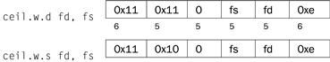
Compute the ceiling of the floating-point double (single) in register fs, convert to a 32-bit fxed-point value, and put the resulting word in register fd.
Compare equal double
![]()
Compare equal single
![]()
Compare the floating-point double (single) in register fs against the one in ft and set the floating-point condition flag cc to 1 if they are equal. If cc is omitted, condition code flag 0 is assumed.
Compare less than equal double
![]()
Compare less than equal single
![]()
Compare the floating-point double (single) in register fs against the one in ft and set the floating-point condition flag cc to 1 if the first is less than or equal to the second. If cc is omitted, condition code flag 0 is assumed.
Compare less than double
![]()
Compare less than single
![]()
Compare the floating-point double (single) in register fs against the one in ft and set the condition flag cc to 1 if the first is less than the second. If cc is omitted, condition code flag 0 is assumed.
Convert single to double
![]()
Convert integer to double
![]()
Convert the single precision floating-point number or integer in register fs to a double (single) precision number and put it in register fd.
Convert double to single
![]()
Convert integer to single
![]()
Convert the double precision floating-point number or integer in register fs to a single precision number and put it in register fd.
Convert double to integer
![]()
Convert single to integer
![]()
Convert the double or single precision floating-point number in register fs to an integer and put it in register fd.
Floating-point divide double
![]()
Floating-point divide single
![]()
Compute the quotient of the floating-point doubles (singles) in registers fs and ft and put it in register fd.
Floating-point floor to word
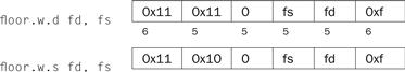
Compute the foor of the floating-point double (single) in register fs and put the resulting word in register fd.
Load floating-point double
|
l.d fdest, address |
pseudoinstruction |
Load floating-point single
|
l.s fdest, address |
pseudoinstruction |
Load the floating-point double (single) at address into register fdest.
Move floating-point double
![]()
Move floating-point single
![]()
Move the floating-point double (single) from register fs to register fd.
Move conditional floating-point double false
![]()
Move conditional floating-point single false
![]()
Move the floating-point double (single) from register fs to register fd if condi tion code flag cc is 0. If cc is omitted, condition code flag 0 is assumed.
Move conditional floating-point double true
![]()
Move conditional floating-point single true
![]()
Move the floating-point double (single) from register fs to register fd if condition code flag cc is 1. If cc is omitted, condition code flag 0 is assumed.
Move conditional floating-point double not zero
![]()
Move conditional floating-point single not zero
![]()
Move the floating-point double (single) from register fs to register fd if processor register rt is not 0.
Move conditional floating-point double zero
![]()
Move conditional floating-point single zero
![]()
Move the floating-point double (single) from register fs to register fd if proces sor register rt is 0.
Floating-point multiply double
![]()
Floating-point multiply single
![]()
Compute the product of the floating-point doubles (singles) in registers fs and ft and put it in register fd.
Negate double
![]()
Negate single
![]()
Negate the floating-point double (single) in register fs and put it in register fd.
Floating-point round to word
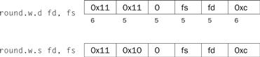
Round the floating-point double (single) value in register fs, convert to a 32-bit fxed-point value, and put the resulting word in register fd.
Square root double
![]()
Square root single
![]()
Compute the square root of the floating-point double (single) in register fs and put it in register fd.
Store floating-point double
|
s.d fdest, address |
pseudoinstruction |
Store floating-point single
|
s.s fdest, address |
pseudoinstruction |
Store the floating-point double (single) in register fdest at address.
Floating-point subtract double
![]()
Floating-point subtract single
![]()
Compute the difference of the floating-point doubles (singles) in registers fs and ft and put it in register fd.
Floating-point truncate to word
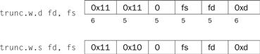
Truncate the floating-point double (single) value in register fs, convert to a 32-bit fixed-point value, and put the resulting word in register fd.
Exception and Interrupt Instructions
Exception return
![]()
Set the EXL bit in coprocessor 0’s Status register to 0 and return to the instruction pointed to by coprocessor 0’s EPC register.
System call
![]()
Register $v0 contains the number of the system call (see Figure A.9.1) provided by SPIM.
Break
![]()
Cause exception code. Exception 1 is reserved for the debugger.
No operation
![]()
Do nothing.
A.11 Concluding Remarks
Programming in assembly language requires a programmer to trade helpful features of high-level languages—such as data structures, type checking, and control constructs—for complete control over the instructions that a computer executes. External constraints on some applications, such as response time or program size, require a programmer to pay close attention to every instruction. However, the cost of this level of attention is assembly language programs that are longer, more time-consuming to write, and more diffcult to maintain than high-level language programs.
Moreover, three trends are reducing the need to write programs in assembly language. The first trend is toward the improvement of compilers. Modern com pilers produce code that is typically comparable to the best handwritten code—and is sometimes better. The second trend is the introduction of new processors that are not only faster, but in the case of processors that execute multiple instructions simultaneously, also more diffcult to program by hand. In addition, the rapid evolution of the modern computer favors high-level language programs that are not tied to a single architecture. Finally, we witness a trend toward increasingly complex applications, characterized by complex graphic interfaces and many more features than their predecessors. Large applications are written by teams of programmers and require the modularity and semantic checking features provided by high-level languages.
A.12 Exercises
A.l [5] <§A.5> Section A.5 described how memory is partitioned on most MIPS systems. Propose another way of dividing memory that meets the same goals.
A.2 [20] <§A.6> Rewrite the code for fact to use fewer instructions.
A.3 [5] <§A.7> Is it ever safe for a user program to use registers $k0 or $k1?
A.4 [25] <§A.7> Section A.7 contains code for a very simple exception handler. One serious problem with this handler is that it disables interrupts for a long time. This means that interrupts from a fast I/O device may be lost. Write a better exception handler that is interruptable and enables interrupts as quickly as possible.
A.5 [15] <§A.7> The simple exception handler always jumps back to the instruction following the exception. This works fne unless the instruction that causes the exception is in the delay slot of a branch. In that case, the next instruction is the target of the branch. Write a better handler that uses the EPC register to determine which instruction should be executed after the exception.
A.6 [5] <§A.9> Using SPIM, write and test an adding machine program that repeatedly reads in integers and adds them into a running sum. The program should stop when it gets an input that is 0, printing out the sum at that point. Use the SPIM system calls described on pages A-43 and A-45.
A.7 [5] <§A.9> Using SPIM, write and test a program that reads in three integers and prints out the sum of the largest two of the three. Use the SPIM system calls described on pages A-43 and A-45. You can break ties arbitrarily.
A.8 [5] <§A.9> Using SPIM, write and test a program that reads in a positive integer using the SPIM system calls. If the integer is not positive, the program should terminate with the message “Invalid Entry”; otherwise the program should print out the names of the digits of the integers, delimited by exactly one space. For example, if the user entered “728,” the output would be “Seven Two Eight.”
A.9 [25] <§A.9> Write and test a MIPS assembly language program to compute and print the first 100 prime numbers. A number n is prime if no numbers except 1 and n divide it evenly. You should implement two routines:
■ test_prime (n) Return 1 if n is prime and 0 if n is not prime.
■ main ( ) Iterate over the integers, testing if each is prime. Print the first 100 numbers that are prime.
Test your programs by running them on SPIM.
A.10 [10] <§§A.6, A.9> Using SPIM, write and test a recursive program for solv ing the classic mathematical recreation, the Towers of Hanoi puzzle. (This will require the use of stack frames to support recursion.) The puzzle consists of three pegs (1, 2, and 3) and n disks (the number n can vary; typical values might be in the range from 1 to 8). Disk 1 is smaller than disk 2, which is in turn smaller than disk 3, and so forth, with disk n being the largest. Initially, all the disks are on peg 1, starting with disk n on the bottom, disk n − 1 on top of that, and so forth, up to disk 1 on the top. The goal is to move all the disks to peg 2. You may only move one disk at a time, that is, the top disk from any of the three pegs onto the top of either of the other two pegs. Moreover, there is a constraint: You must not place a larger disk on top of a smaller disk.
The C program below can be used to help write your assembly language program.
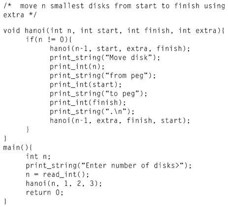
Further Reading
1. Aho A, Sethi R, Ullman J. Compilers: Principles, Techniques, and Tools Reading, MA: Addison-Wesley; 1985.
1a. Slightly dated and lacking in coverage of modern architectures, but still the standard reference on compilers.
2. Sweetman D. See MIPS Run San Francisco, CA: Morgan Kaufmann Publishers; 1999.
2a. A complete, detailed, and engaging introduction to the MIPS instruction set and assembly language program ming on these machines.
Detailed documentation on the MIPS-32 architecture is available on the Web:
MIPS32™ Architecture for Programmers Volume I: Introduction to the MIPS32™ Architecture(http://mips.com/content/Documentation/MIPSDocumentation/ProcessorArchitecture/ArchitectureProgrammingPublicationsforMIPS32/MD00082-2B-MIPS32INT-AFP-02.00.pdf/getDownload)
MIPS32™ Architecture for Programmers Volume II: The MIPS32™ Instruction Set(http://mips.com/content/Documentation/MIPSDocumentation/ProcessorArchitecture/ArchitectureProgrammingPublicationsforMIPS32/MD00086-2B-MIPS32BIS-AFP-02.00.pdf/getDownload)
MIPS32™ Architecture for Programmers Volume III: The MIPS32™ Privileged Resource Architecture(http://mips.com/content/Documentation/MIPSDocumentation/ProcessorArchitecture/ArchitectureProgrammingPublicationsforMIPS32/MD00090-2B-MIPS32PRA-AFP-02.00.pdf/getDownload)
1This section discusses exceptions in the MIPS-32 architecture, which is what SPIM implements in Version 7.0 and later. Earlier versions of SPIM implemented the MIPS-1 architecture, which handled exceptions slightly differently. Converting programs from these versions to run on MIPS-32 should not be diffcult, as the changes are limited to the Status and Cause register fields and the replacement of the rfe instruction by the eret instruction.
2Earlier versions of SPIM (before 7.0) implemented the MIPS-1 architecture used in the original MIPS R2000 processors. This architecture is almost a proper subset of the MIPS-32 architecture, with the difference being the manner in which exceptions are handled. MIPS-32 also introduced approximately 60 new instructions, which are supported by SPIM. Programs that ran on the earlier versions of SPIM and did not use exceptions should run unmodifed on newer versions of SPIM. Programs that used exceptions will require minor changes.