C++ All-in-One For Dummies (2009)
Book II
Understanding Objects and Classes
Chapter 2: Describing Your Program with UML
In This Chapter
Moving up to UML and modeling with it
Designing with diagrams
Going through iterations
Stepping through phases
Performing workflows
The ancient people knew something that we don’t know. Instead of wasting their time writing these big, long sentences and descriptions, they used hieroglyphics, pictures that just got right to the point. One picture = one statement. It wasn’t until the twentieth century that people in the computer world started getting back to their ancient roots and realized that maybe there was something to be said for all those drawings and pictures. One day, while working late, a small group of researchers realized that a nifty way to describe software is through drawings. And thus they came up with the Unified Modeling Language, or UML for short (pronounced, well, just You-Em-Ell).
In this chapter, we talk about what UML is and how you can use it to model your programs. We give a brief overview of the types of diagrams it includes, and we talk about the difference between a methodology and a modeling language.
Moving Up to UML
The Unified Modeling Language has an interesting history. When object-oriented programming was just getting off the ground in the late 1980s, several people came up with different ways to draw various diagrams to help people design their classes. This, of course, was nothing new. In addition to ancient people who used drawings in their hieroglyphics, people have always had a tendency to draw diagrams to describe something. For example, people might draw a chart listing the different parts of their programs. Or they might draw a chart that shows the steps that a program goes through, using a form called a flowchart.
A flowchart is simply a diagram that shows the step-by-step nature of a process, complete with the decision making that the process might involve. For example, we might have a step-by-step process (or algorithm) we use that helps us decide what to do on Mondays. This might look like Figure 2-1.
Figure 2-1: A flowchart shows simple steps in a process.
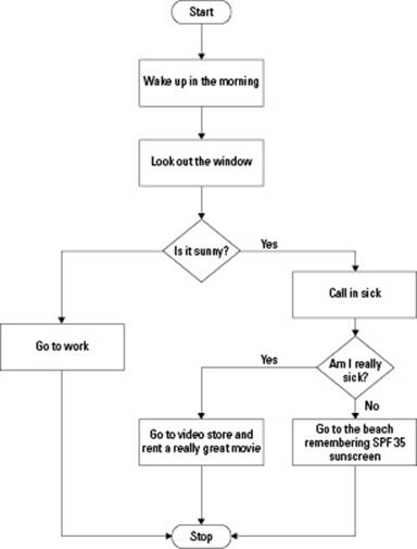
In Figure 2-1, we start at the top in the spot called Start, and then we follow the arrow down to the first box. The first box is a command or statement — something that we do. Then after we do that, we follow the arrow down to the next box. After that we follow the arrow again, but this time we encounter a diamond. A diamond contains a decision. We answer the question, and if our answer is yes, we go one way, but if our answer is no, we go the other way. In this case, if it’s yes, we go to the right, and begin the boxes on the right, following the arrows, responding to any decisions we find. If the first decision was no, we follow the arrows on the left, again doing what the boxes tell us and answering any questions we see in the diamonds.
Well, this whole flowcharting business works great for small, simple tasks. But over the years, software has become far more complex. For one thing, people now build their programs around objects and classes, which simply don’t fit to the flowchart idea. And second, software has become big. Just a quick look at some of the software you use on a daily basis, such as the word processors that run under Microsoft Windows, and you can see that these programs were written by lots and lots of people who seemed like they wanted to add every bell and whistle — whether you even use it or not! And the flowcharts are more suited to small portions of a software package, such as a single function or an algorithm.
And so, over the years, people have pretty much ditched the flowcharting and left it in a time capsule somewhere to be found hundreds of years from now. (Although, a portion of UML — called an activity diagram — is similar to a flowchart.) And during the years since programmers have started ditching flowcharts, a few well-respected researchers in the field of computer science have come up with new ways to draw pretty pictures that will describe a computer program. Several different attempts have been made, but it seems like programmers have finally come up with one that everyone can live with: UML.
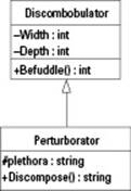
UML takes the concept of flowcharting to a whole new level. Yes, that sounds like it came from a marketing brochure, but it’s true. UML is much more than just flowcharting. UML uses symbols that show how all the classes and objects fit together in your program, and it shows how they interact and collaborate. You then use UML as you design and build your entire software systems. Figure 2-2 is an example of a UML diagram.
Figure 2-2: A class diagram shows classes in UML form.
The three amigos
In your explorations of UML, sooner or later you’re going to come across the term Three Amigos. Although that was a goofy movie back in the Greatest Decade (why, the 1980s of course), in the context of UML, it refers to the three guys who developed UML. Why are they called that? Because after about seven years or so, they finally became friends. It’s true.
For several years, there were three guys who wrote books on object-oriented programming, and they each had their own way of doing things. But worse, the rumor is that these guys couldn’t stand each other. (Who knows if that’s even true.) “My way is better, and I don’t like you, anyway.” Come on guys, can’t we all just get along? Well, in fact, they did end up getting along.
One day, it dawned on them: “Hey! You know what? Like Superman, Batman, and Spiderman, we can all just join forces in one great big hall of justice and make it a better world for all!” That and, “Hey, you know what? Our ideas really aren’t all that different. Let’s combine them into a new, better way of doing object-oriented programming.” Like any time three greats join and put their heads together, the result was something pretty nifty: UML.
By the way, movieland’s Three Amigos are Chevy Chase, Steve Martin, and Martin Short. In UML circles, the three amigos are Grady Booch, Ivar Jacobson, and James Rumbaugh.
This shows two classes, one called Discombobulator and another called Perturborator. Each is inside a box divided into three rows, with the class name at the top, the member variables in the middle, and the member functions at the bottom. The format is slightly different from regular C++ format; the types go at the end, after a colon. (Remember that in C++ you put the types first, as in int Height;).
The first class, Discombobulator, has two member variables, Width and Depth. (Everybody knows that an actual discombobulator has no height; thus, we didn’t include one in this class.) The two member variables are private; therefore, they start with a minus sign, (-), and each is an integer type. The Befuddle member function is public, and therefore starts with a plus sign, +. In the Perturborator class, the plethora member variable is protected, and therefore it starts with a # sign.
Notice the arrow. The arrow shows inheritance, but it goes in the opposite direction of what a lot of people might expect. It points toward the base class. Thus, in this diagram, Pertuborator is derived from Discombobulator.
 The Unified Modeling Language has been accepted by millions of engineers as the standard way for modeling software. The Object Management Group (or OMG, found at www.omg.org) has adopted UML as its official modeling language. The OMG is a consortium of hundreds of software companies that have all joined to oversee the big sea of software development standards.
Modeling a methodology
A lot of people will start reading a book on UML and become a bit disoriented at the beginning because they quickly realize that an important question sometimes goes unanswered: How do you use UML to actually design a complete software package from start to finish? How do you use UML to go through the process of determining what classes you need, building those classes, writing your software, testing it, and all that good stuff? Some books on UML seem to avoid this question for a good reason: UML is not a methodology. It’s not a set of rules and steps for building software. Rather, UML is simply a set of diagrams that you can use while modeling your software. That’s actually a point that many software engineers don’t realize. “What methodology do you use?” “We use UML.” If that’s their answer, it proves they don’t really know what UML is. You use UML with a methodology, and then you have a powerful set of tools for building software.
Modeling with UML
The idea behind UML is that it can be used for modeling pretty much any type of information — not just object-oriented systems — even information not computer-related. As such, UML has many parts. But the great thing about UML is that you don’t need to learn all the parts to use it. You need to learn only the parts useful to your projects.
UML covers all the aspects of the usual software development process. Now we have said that UML itself is not a step-by-step process or methodology for building software. However, the designers of UML have provided enough diagram types and symbols that it can be used with all the different steps of software development. Therefore, to learn UML, learning a methodology along with it is a good idea. In fact, the people who designed UML, The Three Amigos (see the nearby sidebar by that name), have also designed a methodology. Theirs is called the Unified Process. That’s the methodology we use. (And to be quite frank, most methodologies are more-or-less the same.)
Diagramming and designing with UML
The diagrams in UML are simple enough that they can be drawn by hand on a sheet of paper. Of course, this is the age of computers, and using a computer makes sense, so why resort to the old-fashioned method of pencil and paper? But beyond that, there’s a slight technicality as to why paper drawings are not suited to a software design.
When you use UML to design a system, you typically use a computer program called a Computer-Aided Software Engineering (CASE) tool. When you use the CASE tool, you specify all your objects; and as you do, you create your diagrams that describe the classes and how they interact. However, the model itself is the collection of classes — not the diagrams. You can change the diagrams and create new diagrams, but underneath it all is the collection of classes. The collection of classes itself is known as the model. When you draw a diagram, you are simply providing a visual representation of the model. Most of the better CASE tools (such as Rational Rose or Paradigm Plus) include a way to create and modify the model itself. You can usually do so directly or by using the drawing tools included in the CASE program.
When you build a software system by using UML, you work out your classes by using the drawings. In the process, you are creating and modifying the model and the drawings simultaneously. But the model itself is still a separate entity from the diagrams.
A good CASE tool has two ways of looking at your system: The first is through the model itself, which is often depicted as an Explorer-style tree, with the classes and their members listed. The second is through the diagrams. You can use the diagrams to add information to the model; for example, you can use a class diagram to add classes and modify the member variables and functions.
Most CASE tools have a slight catch: If you remove a class from a diagram, you don’t actually remove it from the model. The class is still in the model, just in case you still want to continue working on it and add it to more diagrams. If you really want to remove a class, you have to go to the model itself and remove the class. Fortunately, this applies only to removing classes. You can modify and add classes from the diagrams.
In UML, you can use nine types of diagrams. As you work on these diagrams, your model will evolve. You can make changes to the diagrams, and thereby make changes to the underlying model.
Tables 2-1 and 2-2 show you the nine models. We grouped them into two kinds: static and dynamic. The static diagrams represent the parts of the software system you are building. The dynamic diagrams show how the parts work together and how things take place over time.
The words static and dynamic come up again and again in the computer world. Static refers to something fixed and unchanging, while dynamic refers to something that changes:
♦ In your program, a class is static because you describe it in your code; and after you have described your class, it does not change while the program is running. A class has a certain set of member variables and member functions that you specify in the code. Although the program is running, the members of a class do not change.
♦ The objects, however, are considered to be dynamic, because they can come to life while the program is running, their member variables can change, and they can be deleted.
|
Table 2-1 Static Diagrams of UML |
|
|
Diagram Type |
What It Shows |
|
Class diagram |
The different classes |
|
Component diagram |
The different parts of the system; each part contains classes related to each other |
|
Deployment diagram |
The different computers and hardware involved |
The following list describes the items in Table 2-1 in a bit more detail:
♦ Class diagram: The class diagram shows the different classes and their relationships to each other. For example, a class diagram might show that the class called Skiddle is derived from the class Skaddle, and it might show that the class Skaddle contains as a member a list of Ruddle instances. Typically as you work on a class diagram, you will also be adding and modifying the classes from the model itself.
♦ Component diagram: The component diagram shows the major parts of your software system. For example, all the parts dealing with Discombobulation, including the Discombobulator class and the Perturburator class as well as other related classes, might all be grouped into a single component called SuperSystem.
♦ Deployment diagram: The deployment diagram shows a hardware view of your system. This might include specific computers (such as a Compaq Presario with a gigabyte of RAM), or it might include more abstract hardware components, such as Internet connection. Or it might show hardware components even more generic, such as network node or database server. Nevertheless, these are all hardware components.
 In Windows, a single component often lives in the form of a Dynamic Link Library, or DLL for short. Most DLLs that you find on your computer were built as components. When you use multiple DLLs that other people built, you are building with various software components. You can show these components on a component diagram.
|
Table 2-2 Dynamic Diagrams of UML |
|
|
Diagram Type |
What It Shows |
|
Use case diagram |
The different functions of the software system |
|
Object diagram |
Instances of the classes and their relationships to each other |
|
Collaboration diagram |
How instances work together with other instances |
|
Sequence diagram |
The time sequence of objects working together with other objects |
|
Statechart diagram |
The lifecycle of a single object in terms of states |
|
Activity diagram |
A sequence of steps; much like a flowchart |
The following list describes the dynamic diagrams in a bit more detail:
♦ Use case diagram: The use case diagram shows the different individual functions that the software package can perform. Here we mean function in a generic sense, like a process, not like a C++ function consisting of a set of code. A word processor might have a use case calledSet italic. This use case represents the function of setting the italic style for the highlighted text. A Web browser might have a use case called Go, which takes a Web address and pulls down and displays the appropriate Web page.
♦ Object diagram: The object diagram describes the instances of the classes. This is in contrast to the class diagram, which shows the classes but not the actual instances. The reason that the object diagram is considered a dynamic diagram rather than a static diagram is because objects themselves are considered dynamic. Objects can change while the program is running. Classes, on the other hand, do not change while the program is running.
♦ Collaboration diagram: As your program runs, the code for an object’s member function might call a member function in another object. In this sense, the two objects are working together, or collaborating, just as two people might collaborate to rob a bank. A collaboration diagram shows how the different objects collaborate.
♦ Sequence diagram: A sequence shows the collaborations of the objects over time. So if your program is a model of two bank robbers failing because they get into a severe argument over which door to leave the bank through, and you have two objects that represent the two bank robbers, this diagram would show them calling each other’s member functions over time. These functions might be things like Insult and Criticize and PolitelyDisagree.
♦ Statechart diagram: A statechart diagram is like a sequence diagram, but it shows only one object. It shows how an object changes over time, from the time it is created until it is deleted.
♦ Activity diagram: An activity diagram shows the step-by-step nature of a single member function. It is actually a type of statechart:
• A statechart diagram shows how an object changes from state to state.
• An activity diagram shows how a member function moves from one activity to the next. In that sense, each state in the activity diagram is an activity.
In the world of UML, when an object’s member function calls a member function of a second object, the process is called sending a message. The first object sends a message to the second object. This terminology is not new to UML; the original object-oriented language, Smalltalk, used the same terminology. In Smalltalk, objects sent messages to other objects. You use a collaboration diagram to show how one object sends a message to another object. Or you can say that the collaboration diagram shows member functions calling the member functions of other objects. They both mean the same thing.
A popular word among software engineers is lifecycle. Really, the word basically means life. A software development process has a lifecycle: You start building the software, go until it’s all built, update the software as needed, and then retire the software when you’re finished using it; that’s the lifecycle of the project. However, in many senses, it does cycle back: You get bug reports from customers, and you fix the bugs, and you eventually release another version of the software. Objects have lifecycles too: When you create an instance, you are beginning the life of the object. Then, during the object’s lifecycle, you do things to the object like call its member functions and modify its member variables. Then, when you’re finished, you delete the object. That finishes the lifecycle.
Software engineers like to think in terms of states. A state is simply the current situation in which something exists, like the state of the nation or the state of affairs. These represent the current situation for the nation or the affairs. Or somebody could be in a state of all-out confusion. That represents the current state the person is in. An object also has a particular state: The Caboodle class might have member variables PenCount and NotebookCount, which represent the number of pens and the number of notebooks inside an instance of theCaboodle class. A particular instance of the Caboodle class might have the value 7 for PenCount and the value 3 for NotebookCount. Thus, the current state of this particular instance is PenCount=7, NotebookCount=3. The Caboodle class might also include a member function called AddPen, which takes no parameters and simply adds 1 to PenCount. When you call AddPen, you are changing the state of the object.
 When you consider the state of an object, you need to look at only the member variables. The values of the member variables together represent the state. The member functions may modify the state, but because the functions themselves do not change during the life of the program, they do not represent part of the object’s state. Also, remember that one object can contain as a member another object. The current state of the outer object would include the state of the object that it contains.
In the world of UML, the concept of a metadescription comes up again and again. Meta is a prefix to a word, and it usually means the next level up. For example, with metadescription, we could first describe a tree by writing information about the tree. Then we could describe the description: “It was a beautiful paragraph with flowing words that brought the tree to life.” Now that previous sentence itself is what we are referring to right now in this sentence. Do you see what is happening here? We’re describing something, and then we describe the description, and then we describe that description. Each time we move up “one level of abstraction.” The term metadescription, then, means a description of a description.
In UML, you encounter meta terminology all the time. For example, a class represents a type of object. But the word class is a kind of classifier. Another kind of classifier is type. So consider this somewhat philosophical concept: A class is a kind of classifier, at least from the perspective of the UML diagrams. But a particular class itself has certain attributes about it, such as the class name and the names and types of the members. That information is a metaclass. If you’re not totally confused and you find this fascinating, we highly recommend reading Gödel, Escher, Bach: An Eternal Golden Braid, by Douglass R. Hofstadter (Basic Books, 1999) or, for a slightly easier read, Metamagical Themas: Questing for the Essence of Mind and Pattern, also by Hofstadter (Basic Books, 1996).
Building with UML and the Unified Process
UML is not a methodology. That means that UML, by itself, is not a step-by-step process for building software. Rather, you can think of UML as a language you use for describing your software as you are building it. The language, however, is not a verbal talking language with a bunch of engineers in a room yelling and arguing. Yes, that sometimes happens, but fortunately it’s neither a part of UML nor required. UML is a visual language. There’s that adage about a picture being worth a whole bunch of words, or something like that, and it holds up here, too. You describe your software with diagrams. These diagrams provide a full description of your software.
But you create the diagrams as you move through a process. The process is a methodology that you use; the one that we use and describe in this book is the Unified Process. There are five main steps (which tend to be the same for most methodologies). These main steps, which are calledworkflows, are as follows: requirements, analysis, design, implementation, and testing. When you think of the steps you would do to accomplish pretty much anything that’s not computer-related, you can probably see that you often use these steps.
For example, suppose that you’re going to build a time warp device so you can skip that dentist appointment next week. First, you decide what you need to build; this is called the requirement collection. In this case, you need a device that takes you forward into time, probably a specified amount of time. So you’ll want a display on the device and a keypad so you can enter the amount of time to move forward. And you’ll probably need a button to start the time warp. Those are the requirements for the project.
Then you think about how you’re going to do the time warp and what you’ll need, and you analyze the project. In this case, you’ll need the actual time warping portion consisting of the relativistic universe bender as well as the main interface portion, where you get to control the thing. This step is called the analysis.
Next, you begin carefully designing the invention but not actually building it. This is the meat of your work, where you draw diagrams of what you’ll be building and how the different parts work out. You draw how your particular version of the relativistic universe bender works and the parts involved in it as well as all the other major components of the system. This is the design step.
Then you build, or implement, the thing. This is the fun part, where you go into the shop and start hammering and pounding and defying gravity to build the device! And of course, this step is called the implementation.
But you’re not finished yet; finally, you have to test it. For this, you pay off the guy next door to take a ride in your time machine to see whether it works. If not, he can report back to you and let you know what went wrong. (Assuming that he makes it back.)
Now this is all good, but some issues can come up that these basic five steps don’t handle. For example, many people who try building a large software system quickly discover the chicken-and-egg syndrome. The problem is this: If we’re in the middle of the analysis workflow and we’re supposed to be getting our rough classes down, how can we possibly know all the classes we’re going to need until we get down into the code and start writing the thing?
For this reason, many people have the attitude skip engineering and just code the stupid thing! But just imagine what your time warp device would be like if you tried to build it without planning it. After you get the thing completely built (more or less), do you really trust it? Would you take a ride in it, rather than just pay the unsuspecting neighbor? Well the same is true for software. If you just dive in and start grinding out code, racing for the finish line, how can you be sure that you covered everything? Did you miss anything? Most likely. And does what you wrote run perfectly? Doubtful.
Fortunately, there’s a way to fit everything together. It uses steps called iterations.
Speaking iteratively
Suppose we want to build a new kind of Web browser. This Web browser will be super-smart and will just automatically know what Web site you want to go to by tapping into your brain waves. When you wake up in the morning, you will hear your ears ringing with the message of a faint distant phrase, “Where do you want to go?” You think, “Wouldn’t it be fun to see the Smithsonian?” Then you walk to your computer, sit down, and first the browser brings up the site for the Smithsonian, and then it brings up a site that shows flights, hotels, rental car information, and maps to get there. Now wouldn’t that be a seriously cool Web browser?
So, being a good engineer, you follow the formal steps of building it. You draw your requirements, and you even interview your friends to see what ideas they have about such an amazing work of software. Then you analyze the different parts and come up with the functionality of the software, and you even draw some sample screens. Next, you move into the design workflow, fleshing out the basic classes you built in the analysis workflow. And finally, you begin coding. You code for weeks, when suddenly — WHAM! — you discover that something is seriouslywrong: You completely forgot that you need to write a portion of the software that does the grunt work of connecting to the Internet, then to a specific site, anddownloading the appropriate Web page. In effect, you failed to consider the low-level communications portion of your super-cool program. And while ruminating over this problem, you also start to think of some other things you failed to consider earlier: After you receive the Web page, are you going to draw it on the screen, or are you going to buy some C++ library that will display it in a window for you? The latter would make your life easier, but regardless, you had not considered this.
That’s when you get frustrated and start considering that position your cousin offered you to be a mime out in front of City Hall downtown, drawing customers in to buy hotdogs from your cousin’s hotdog stand in front of the Hall of Justice.
What exactly happened? Here’s what happened:
1. You didn’t realize until coding time that the display part of the browser, the part that shows the Web page on the screen, would be extremely complicated and might require the purchase of a library that displays the browser pages for you.
2. You didn’t even consider that you would need a low-level communications system. Or did you? Maybe Windows already provides it. But either way, you hadn’t thought of that during the analysis or design workflow.
As you dwell on these problems, you notice more bad things. For starters, if you decide to do the low-level communications system, do you make it its own library that you could potentially use in other programs? Or do you buy a library? Or is one already available on the computer? You’ve heard that Windows has such things built-in, but you’re not sure.
So you know what happened, but why did it happen? Finally, you put your finger on it: It’s another chicken-and-egg syndrome, and it goes like this: How could you have known you needed a low-level communications system until you finally started coding the thing? Yet, you needed that information while you were in the analysis and design workflows, before you started coding it! In effect, which comes first, the chicken (the analysis and design) or the egg (the realization that you need a low-level communications system)?
Although this might sound horribly apocryphal, it happens all the time in the software world. If you want to see tempers flare, visit some software engineers when such an abysmal situation arises.
Well, we think we’ve made our point, but before you rush off to the psychiatrist for a nice, big supply of antidepressants, fear not: The Unified Process is here to save the day!
The designers of the Unified Process knew well that these problems occur. And thus, they made a set of higher-level processes called phases, and put the five workflows inside these higher levels. During each phase, you cycle through several of the five workflows. Then when you’re finished, you can cycle through them again, or you can move on to the next phase. And you once again cycle through several of the five workflows.
The idea is that each time you cycle through several of the workflows, you finish an iteration.
Phasing in and out
The Unified Process consists of four main phases. In each phase, you focus on various workflows, such as analysis or design, but you are free to move forward to later workflows. The only catch is that, although you can start and stop at any workflow, you must complete all the workflows in between for a single iteration. For example, you can’t jump from analysis to test; you must first do analysis, then design, then implementation, and finally test. Here are the phases of the Unified Process:
♦ Inception: During this phase, you determine the objectives of your software.
♦ Elaboration: In this phase, you analyze and design your software.
♦ Construction: This is when you focus primarily on coding the software.
♦ Transition: This final phase is when you deliver the software. For retail software, this means sending it to the disc duplicators and packagers; for in-house software, it means shipping it to the groups who will be using it.
And here’s the really great part: Each of these four phases can be a whole set of workflows: Requirements, analysis, design, implementation, and testing. But how can that be, my dear friend, you ask? It goes like this: In the inception phase, you gather requirements and go through the process of getting some basic analysis and design down. And if need be, you even do some rough prototypes of the software, where you basically play around and try out some things. In effect, you do a basic coding (implementation). And yes, you might even spend a little time testing it. But you’re not building a full-scale software system, by any means! You’re just doing pieces and parts and parts and pieces. But more so, you’re doing a proof of concept just to see if you think, as a professional engineer, this idea is going to fly. And undoubtedly, you will run into some issues that the original requirements failed to take into account.
For example, suppose that you’re going to build a word processor program that beats Microsoft Word hands down. Now, if you have used Microsoft Word and opened up a really big document (like several hundred pages), you may have noticed something happens on occasion. Sometimes when you make a substantial change that will drastically affect the page count, such as changing the margins, Microsoft Word repaginates. And as it repaginates, you might find that some vital paragraphs get split, with maybe one line of text at the end of one page and the rest of the paragraph on the next page. That can create an ugly document, and thus, Microsoft Word includes a feature called Keep paragraphs together as an option in a dialog box.
Now if you’re building a word processor, it’s possible that you won’t think of this hair-splitting, paragraph-splitting issue until well into the coding. So what do you do? Most likely, during one of the first two phases, after you have a basic prototype, you might notice that sometimes paragraphs are getting broken up at inconvenient places. The solution? Include an option to keep paragraphs together. And so you go back to the requirements and add a piece to the required functionality: an option for keeping paragraphs together!
Now if you’re building a super-cool Web browser that specializes in mind-reading, during the inception phase you might do a basic prototype that has all the major features, even if they don’t work well. But during that time, you spot something you left out: the communications system. But now you know that you need it! So you return to the analysis phase, where you can actually add it, perhaps as a component! Cool, no?
Now each time you backtrack through your workflows and change something, you begin a new iteration. Therefore, you can see that the phases are broken up into iterations, each with several of the five workflows. And you may go through several iterations within a single phase.
You don’t have to get all the way to the end, to the testing workflow, before you back up. Thus, each iteration might consist of only one or two workflows.
If all this sounds a little strange, look at it this way: If you discover that you don’t have something quite right, what do you do? You go back and fix it! But software engineers like to sound a bit more technical than that, so instead they say that they begin a new iteration.
The inception phase
The inception phase is the first phase, where you start getting things off the ground. During this phase, you may not make it to the point where you’re coding a prototype and finding problems. But if you’re building a big project, you just may make it to the point of coding a prototype. However, if you are, you will probably be writing small prototypes of only various portions of the project.
And during the inception phase, you try to do the following:
♦ Determine whether the project is feasible. The term feasibility is a word that comes up again and again, and it’s primarily the result of people having great ideas but later determining that, well, frankly, those ideas are not practical or reasonable. But instead, businesses prefer the kinder, gentler term, feasible.
♦ Determine the primary requirements.
Requirements gathering is a particularly touchy issue because, during that time, people are going to want to include everything. Not only will they want the software to browse the Web, but they will also want it to inject the Web page back into your brain and also give you the ability to download it straight from your brain to your friends’ brains and print a copy by just laying your finger on the printer. They want the software to do everything.
But thankfully, during this time, you start to map out the project, probably build some prototypes, and determine what it really should do. Is it feasible to transfer the pages back into the brain, or is that technology not going to come for another year or two? If not, it probably isn’t feasible.
The goal in this phase is to solidify the requirements and do some basic analysis. During this time, you will get people to agree to what it is you’re going to build. (These people are called stakeholders because they hold a big stake — like their jobs — in the success of this software. And when you finish writing it for them and they become millionaires, they will treat themselves to a nice, big steak.) You will also get them to agree on things such as what computers the software will run on and the software’s limits. For example, can the browser read multiple people’s brains or just one person’s brain at a time? (That’s a limit.) And will it run on Windows, or will it also run on Macintosh, Unix, and Linux?
And, of course, the business folks will want a bit of say in all this, too. So the goals of this phase will also include things such as a schedule and cost for the project: How soon will you have it completed, and how much will it cost the business? Will you need to hire more engineers to work on the project? And will you need to buy more computers and tools, such as compilers?
And finally at the end of this phase, you will want to have a basic architecture of the system, consisting of UML diagrams. Now these diagrams may be rough and basic, but they will provide an overall outline of the system.
The elaboration phase
During the elaboration phase, you solidify the functionality of your software. You use tools called use cases — descriptions of individual pieces of the software functionality. For example, a word processor would have use cases such as set italic on, set italic off, print, set left-align, anddelete a page. The use cases are all the things you can do with the software.
Also during the elaboration phase, you develop a plan for when you build the thing. This means elaborating on the basic designs you created in the inception phase by going through more analysis and design.
Some of the major goals of the elaboration phase are to finalize the scope of the software and to incorporate any changes to the software (for example, after further inspection, you may have determined that more things were not feasible and that other parts were); to finalize the project plan, including the number of people you need and how long it will take; and to make sure the stakeholders are all happy and hunky-dory with the project.
And during the elaboration phase, you also create a first, rough-draft version of the software. Yes, you may have built some code in the inception phase, but that was just prototyping for determining feasibility. You don’t use that rough code from the inception phase in the real coding. Here, however, you make a first run of coding the real program. To get there, you continue with your analysis and design, and get into coding (implementation). Of course, the software is just a rough draft, but it is more than a prototype; unlike the preceding phase, in the elaboration phase you’ll be saving much of the code and reusing it for the next phase. Thus, you once again move through iterations, cycling through workflows, such as analysis, design, and implementation.
The construction phase
During the construction phase, you continue with the implementation. But by now, all your analysis and design should be pretty much finished. Everybody (including the famous stakeholders) agrees by now on what the software will and won’t do, how much it will cost, how long it will take to build it, and how many people will work on it. But further, you have drawn up your groups of classes that you will be designing and have decided how the classes fit together and how they communicate with each other. The analysis and design is ready for prime time, and now you can focus on actually making the system work. Here you look for parts that don’t quite fit together, and you fix problems to make them fit together. You make sure that your system has no major holes whereby the entire thing could come to a crashing halt under a strange, unexpected situation. In a word, you make your software stable.
If you were involved with computers in the early 1990s, when things were finally settling down and we were starting to see practical, real software, you probably also saw something else: little error messages that popped up called general protection faults (GPFs). GPFs appeared when the program really screwed up bad, and the only way to fix the program was to attempt to click the Ignore button to ignore the error (an option that, trust us, never worked) or abort the program. We remember those days well because they made us start to consider job offers from distant cousins who rented beach umbrellas on the Gulf of Mexico.
Now why did these errors happen? Because the software wasn’t stable. You managed to put the software into a situation that the programmers didn’t expect, and the thing choked, coughing up a general protection fault. And why did the programmers create software that allowed this situation to occur? Because they didn’t thoroughly go through the construction phase!
The construction phase includes implementation and testing workflows. You may have some analysis and design flaws, but they will be little; the main time you’ll see these flaws is if you find you forgot something or need to change something in the classes. By now, you will be going through iterations of writing code, testing, testing, testing, and finally more testing. When the testers encounter errors, you go back and fix the code. Then, eventually, the testers determine that they can’t find any more bugs! The day is done! You are ready to ship!
Thus, if you follow the construction phase properly, you will limit the number of operating system errors that pop up when your program goes haywire — because if you did everything correctly, it shouldn’t go haywire!
If you are heading up a project where you will be using the Unified Process to design a large-scale software system, you will want to give your testers a certain amount of authority. Think of the testers as the quality assurance people. And in fact, some companies call them Q/A engineers instead of testers. Your testers shouldn’t allow your company to put its name on the software until they say it works. This has multiple benefits because it allows the Q/A engineers to feel a certain amount of authority, and it also puts a heavy responsibility on them, which will help ensure that they do a thorough job. And that will help ensure that your software is both good and stable. Sounds like a good plan to us!
The transition phase
The transition phase is both the happiest time and the scariest. As a software engineer, we know that this can be a frightening time because the final moment of truth has arrived: Did you and the rest of the team build a product that is actually going to work? Or is it going to get out on the customer’s computer and crash and burn?
Most likely, because you did everything correctly in the first three phases, the software will run on the customer’s computers. However, just because you did it right doesn’t mean that you won’t be anxious. But relax: If you are shipping a piece of software to one specific customer, you and the other engineers will probably be on hand that day for the big installation. It may not go perfectly at first, but in our experience most of the problems will not involve faulty software. Rather, the customer’s computers will not be set up quite right. Fortunately, such problems are pretty easy to track down and fix.
But if you’re shipping software that will be sold through the retail chains to potentially millions of people, the transition phase has an important step that many companies don’t think of. In this final step, you choose a workday and invite all the employees who want to come in for a giant beat-up-the-software party! Yeah! They all come in, and you pass out CD-ROMs containing your software. These are copies of the CD-ROM you intend to ship, assuming that all goes well today. The employees get free pizza and soft drinks (beer isn’t allowed on company property; besides you want them thinking clearly!), and they get to beat the stuffing out of your software. They install it, play with it, manipulate it, use it, fiddle with it, and do everything they can with it; and in the process, give it a pounding it will never forget. And if they encounter a problem, they let you know (politely, of course). But your personal job, on this day, is not to join them in testing the software. Your job is to get to work fixing any problems they find. Generally, they will be minor problems, and you’ll be able to crank out the fixes in no time.
If you actually have a big test day like this, try to make it as exciting as possible. Free pizza, free soft drinks, maybe loud, fun music blasting, and maybe a relaxation room where people can go and goof off for a few minutes and forget about the project. Believe us, these folks will enjoy this special day if you make it exciting for them. And the result, of course, is a successful software package!
Moving Forward with UML
Although you spend much of the time on the construction phase, a lot of the brainwork is in the analysis and design phases. That’s where UML comes into play. You use UML to map your classes, draw them, work with them, and design them. Therefore, for the rest of Minibook II, you find various discussions about UML and processes that usually take place during analysis and design. However, some take place during the requirements phase.
The next two chapters focus on the nine types of diagrams you use during your requirements gathering, analysis, and design. The first chapter focuses on the static diagrams, and the next chapter focuses on the dynamic diagrams.
All materials on the site are licensed Creative Commons Attribution-Sharealike 3.0 Unported CC BY-SA 3.0 & GNU Free Documentation License (GFDL)
If you are the copyright holder of any material contained on our site and intend to remove it, please contact our site administrator for approval.
© 2016-2025 All site design rights belong to S.Y.A.