C++ All-in-One For Dummies (2009)
Book II
Understanding Objects and Classes
Chapter 3: Structuring Your Classes with UML
In This Chapter
Drawing classes in UML
Drawing inheritance and other relationships
Building components with UML
Deploying the software
When you use the Unified Modeling Language (UML) to design software, your diagrams have two aspects. One is static, and the other is dynamic. The static diagrams represent the things that do not change while your program is running. For example, a class does not change while the program is running. When you write the code, you write the class name, member variables, and member functions, and you notate what is private, protected, and public. After you compile the program, this information does not change; it remains static. This is in contrast to the information you represent in the dynamic diagrams, where the information can change. Dynamic diagrams include things like object creation and deletion as well as object collaborations (objects working together, or collaborating, conspiring, plotting, and scheming like good little classes).
In this chapter, we discuss the different types of static diagrams. These are
♦ Class diagram: A class diagram represents the different classes in your program.
♦ Component diagram: A component diagram represents the major parts, or components, of your program.
♦ Deployment diagram: A deployment diagram represents the different computers and hardware that your program will ultimately run on.
 In this chapter, we talk about the UML diagrams. And although you’ll rarely hear us say this, there is one thing we don’t talk about much — at least, not in this chapter: We do not cover the methodology. (We cover that in Minibook II, Chapter 2.) UML is a language that you use to design software. A methodology is the process you use to design software. The process that we recommend is the Unified Process. In this chapter, we discuss the diagrams and we mention the parts of the process where you might use the diagrams. So in this chapter, you get to make lots of pretty pictures.
Drawing Classes
Like so many things around us, objects can have other objects inside of them. For instance, an alligator object could have inside it . . . well, that’s probably not the best example. Rather, a printer object would have a toner cartridge inside it. These could be separate objects, each belonging to its own class. One might be the LaserPrinter class, and the other might be the TonerCartridge class.
In this sense, the two classes are connected. The connection is not by inheritance; nevertheless, they have a relationship.
You can take this relationship a step further. We have a container of blank, writeable CD-ROMs (or CD-Rs). The container could be an instance of class CDROMHolder. The items inside the container might each be an instance of class CDR. In this case, a single instance ofCDROMHolder might contain several instances of CDR. So whereas the LaserPrinter instance contained a single TonerCartridge instance, the CDROMHolder contains several CDR instances. Another example is the class Porsche parked in our driveways. It contains exactly four instances of GoodyearTire. (Yes, we’re dreaming.) And so you can see there are several possibilities here:
♦ Exactly one instance: An instance of a class might contain exactly one instance of another class.
♦ Fixed amount of instances, greater than 1: Each instance of a class might contain an exact number of instances of another class. This number does not change between instances.
♦ Varying number of instances: Each instance of a class might have a different number of instances of another class. This amount might vary from instance to instance, and it might even change over time for a single instance.
As for the final item, you can see that when we remove a CDR instance from the CDROMHolder instance, the number of instances the holder contains decreases by 1. Or if we put a CDR instance back, the holder goes up by 1. If we buy more and refill the holder, it goes up by more than 1. But with the Porsche that we really believe is parked outside, the number of tires stays the same.
As you analyze the classes to build your program, you might find some disagreement here: When we go in to get new tires, the car will be raised up, and the mechanics will remove the old tires, one by one, until no tires are on the car. Then they will put new ones on, one by one. Thus, the number of tires isn’t fixed throughout the life of the instance. But how you build your class depends on the needs of the people using the program. It’s possible that you won’t need to consider that aspect and can therefore treat the number of tires as fixed. Or you may need to include the tire replacements, in which case you would not treat the number as fixed.
And here’s another example: If you’re writing a program for a racing game or simulator, you may want to have the ability for wrecks to occur and tires to come off the car. Then you would need to vary the tire count.
How you design your classes depends on the situation. Always assuming the same thing for a similarly named class as it appears in different programs is not practical. Some programs may require a class to be different from a class in another program, even though both classes happen to have a similar name.
Another kind of relationship is inheritance. The LaserPrinter class might be derived from the Printer class.
Inheritance can also be complex. You may have a class and also have two classes derived from it. One of these two classes might have two classes derived from it, and another might have only one. And from there, you might have no more classes derived. C++ offers great flexibility.
 You can look at design issues in another way. A class is a kind of classifier. In this regard, you can imagine an inheritance showing different words for kind. One would be class and one would be classifier. Then class is derived from classifier. Another classifier is type, and therefore type would be derived from classifier as well. (Remember, that integers are types, for example.) So from this perspective of the metainformation or metadata, you can think of int as an instance of the classifier type. And you can think of LaserPrinter as an instance of the classifier class. And the particular printer on our desks, then, is an instance of LaserPrinter. This requires an abstract way of looking at things, but if you can keep up with this, you’re ready for some serious class designs. That’s because you’ll understand how classes all fit together in the greater scheme of things.
Mapping classes with UML
You can create a UML diagram that shows several classes and their various relationships. Take a look at Figure 3-1. This figure shows three classes, Printer, LaserPrinter, and TonerCartridge. Pay close attention to the lines connecting these three classes. The lines are different because these classes relate to each other in different ways.
First, the line connecting Printer and LaserPrinter shows inheritance. The fat, hollow arrow points to the base class. Thus, LaserPrinter is derived from Printer.
Although you won’t hear us use this term much, an opposite to the term derived from is generalizes. Thus, if LaserPrinter is derived from Printer, another way to say this is Printer generalizes LaserPrinter. The idea is that Printer is a general form ofLaserPrinter, while LaserPrinter is a specific form of Printer. The reason why we prefer not to use the term generalize is that when you create a hierarchy of classes, you typically create the base class first. Then you derive a new class. So to us, the term generalize is counterintuitive. And our brains don’t do well with counterintuitive ideas. (However, we should add, in all fairness, that a common way to come up with classes is by noticing similarities between two classes and then coming up with a single class to serve as a base class. So in this sense, generalization makes sense.)
Figure 3-1: The lines pointing between the classes show different kinds of relationships.
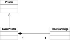
Now look at the line connecting LaserPrinter to TonerCartridge. This is called a composition, and this word means that the two classes are associated. Therefore, each LaserPrinter instance will contain exactly one TonerCartridge instance. How you implement this later is your choice, but most likely you will include in the LaserPrinter class a pointer to a TonerCartridge instance.
In this second line, the end with the filled diamond refers to the whole that contains the part. Thus, LaserPrinter is the whole, and it contains the part TonerCartridge. Notice also that two numbers are below the composition line. The one on the left means that oneLaserPrinter instance is in the association, and the one on the right means that one TonerCartridge instance is in the association.
Now look at Figure 3-2. Here, you have a diamond and a line, which again mean composition. But this time, the Porsche class has a 1 by it, and the GoodyearTire class has a 4 by it. That combination means that exactly one instance of Porsche will have exactly four instances ofGoodyearTire. In other words, one car has four tires.
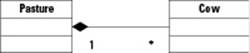
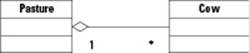
Next, look at Figure 3-3. Again, you see an association, but this time it is between the Pasture class and the Cow class. But in this case, the Pasture class has a 1 by it, while the Cow class has an asterisk (*) by it. The * means that any number of Cow instances can be associated with any single Pasture instance. In other words, a single pasture can have multiple cows running around on it. When you put * in the UML diagram, it means that any number of instances can be in the association, including 0. Therefore, a Pasture might have no cows in it (they’re all in the barn getting milked), or just 1 could be in the pasture, or 100 cows could be out in the pasture, lounging around.
Figure 3-2: The diamond and the line together mean composition.
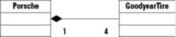
Figure 3-3:Many instances of the class with the * nearby can be associated with the class with the 1 nearby.
Other possibilities for denoting the number of items in a relationship are also available. These possibilities are called multiplicities. Table 3-1 lists them.
Attributes and methods
In the object-oriented world, you’re likely to hear two words many times over: attribute and method. An attribute is simply a member variable, and a method is just another name for member function. These two terms are the official UML terms. However, most people in C++ usually don’t use them, except perhaps when drawing UML diagrams. Instead, most C++ programmers prefer the terms member variables and member functions. You can use whichever terms you prefer, and whichever terms you hear other people saying. In this book, we use attribute and method when talking specifically about UML diagrams and not referring to C++ code.
|
Table 3-1 Multiplicities |
|
|
Symbols |
What They Mean |
|
1 |
Exactly one instance |
|
n |
Exactly n instances (where n is any number) |
|
m..n |
Anywhere from m to n instances allowed; examples are 0..1 or 1..10 |
|
* |
Any number of instances, including 0 |
|
0..* |
Any number of instances, including 0.(same as *) |
For example, if you have two classes, one called Vacuum and another called ExtensionTube, and you see a 1 on the side with the Vacuum and a 1..4 on the side of the ExtensionTube, that means for each (1) instance of Vacuum, you can have anywhere from one to four (1..4) instances of ExtensionTube.
But wait. We thought these class diagrams were supposed to be static, not dynamic! And that’s true: They are still static diagrams, although the line between static and dynamic is a little blurred. We could go into a big philosophical explanation about why class diagrams are indeed static (for example, you write a class that contains a single array, and that does not change), but instead, let us say this: Just consider a class diagram to be static, and recognize that some blurry distinctions exist. It’s not a big deal.
Inheriting in UML
If you want to specify inheritance in UML, you simply draw an arrow from the derived class up to the base class and don’t fill in the arrow. But you can show other types of inheritance with UML.
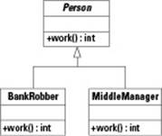
If you want to specify that a base class has abstract virtual functions, you specify those in the class using italics. For example, in Figure 3-4 we have a base class called Person. This is an abstract class because it contains an abstract virtual function, work. The function is abstract virtualbecause it is in italics. (And thus, the class itself is virtual. Remember that a class that has at least one abstract virtual function is therefore itself abstract.)
The two classes derived from Person, BankRobber and MiddleManager (we just thought those made for an interesting combination), each override the work function. Therefore, they are not abstract. And thus, you can create instances of BankRobber and MiddleManager.
You may have noticed that, so far, we have not mentioned a way to specify a virtual function in UML. You can specify a member function as abstract, but what about just plain old virtual? You can’t. The virtual keyword is unique to C++, and the word simply means that you can override a function. So how do you specify virtual? Many CASE tools include an option in the model that lets you specify a member function as virtual.
Figure 3-4: You can show abstract classes in UML by putting a method in italics.
Aggregating and composing classes
When you associate two classes but not by inheritance, you can do it in two common ways: composition and aggregation. Consider the LaserPrinter class and its association with the TonerCartridge class. A toner cartridge is a fundamental part of a laser printer, but a toner cartridge can’t be inside more than one laser printer at a time. This is composition. Think of composition as a very strong bond between two objects.
Aggregation, on the other hand, refers to two objects that are more loosely connected. In an office, you may find hundreds of computers and a dozen or so laser printers. The laser printers can function on their own, and they interact with many different computers. Meanwhile, the computers can each interact with many different laser printers. This is a much looser connection; this is aggregation.
But this does not imply composition is only for one-to-one relationships, and aggregation is for many-to-many. Instead, composition simply means a much stronger, tighter relationship. A toner cartridge is an intimate part of a printer and therefore is in a composition relationship. But a printer is not such a tight, important part of a computer. The computer can live without the printer, and vice versa, which suggests an aggregation.
In UML, you can distinguish the two based on the quality of the diamond. Doesn’t that sound nice? However, in this case, we’re talking about the diamond shape on the diagram, not an actual diagram. For composition, the diamond is filled in solid black. For aggregation, it’s not filled in; it’s just an outline. Figures 3-1 through 3-3 show composition. Figure 3-5 shows aggregation.
Notice that Figure 3-5 has the same classes that we put in Figure 3-3. But this time the diamond is not filled in. This means we modified the diagram to make it an aggregation rather than a composition.
Composition and attributes
A close similarity exists between a composition and an attribute. When each LaserPrinter instance has its own TonerCartridge instance, you have a choice: You can either draw a composition line between LaserPrinter and TonerCartridge, with the diamond on the side of TonerCartridge, or you can simply give the LaserPrinter class a member variable (attribute) of type TonerCartridge. After all, when you take the composition and write the code for the class, the composition will manifest itself in the form of a member variable. So which do you do? Really, it’s up to you (but don’t do both at once). But here’s one rule. (And as we would like it with most rules and laws, this is not strict.) If you have a common class that you use throughout your program (one that you might think of as a utility class) and it appears as a member variable in many classes, it is probably best to make it an attribute, rather than show it through a composition line, simply because it will keep your diagrams from getting cluttered.
Figure 3-5:When the diamond is not filled in, you have an aggregation.
When you use UML, you can’t have two diagrams showing two conflicting associations; thus, we can’t have both Figure 3-3 and Figure 3-5 in a single UML model. Instead, we changed Figure 3-3 to show an aggregation, and we showed aggregation in Figure 3-4.
 Another way to look at composition is through ownership. If it makes sense for one object to own another object, this is composition. For example, one LaserPrinter instance would have its own TonerCartridge instance. Another LaserPrinter would have a differentTonerCartridge instance. That is, the two LaserPrinters cannot share a single TonerCartridge. Thus, you can think of each LaserPrinter instance as owning a TonerCartridge instance. In that case, you can use composition.
Building Components
When you are building software, grouping various classes together into components is often convenient. Ultimately, when you are developing by using C++ on Windows, a component often ends up as a Dynamic Link Library, or DLL for short. (Unpronounceable; so we just say Dee-El-El.) A DLL is simply a file that contains a bunch of code that other programs can use. The other programs load the DLL and then call its functions. But nothing particularly magical surrounds the DLL. It’s just a bunch of compiled classes and functions stuffed into a single file. (And it’s compiled; it’s not source code.)
Or a component might end up in the form of something called a static library. A static library is much like a DLL in that it contains a bunch of code for your program to use. However, when you build your program, the linker (which is the tool that performs the link process) combines the code in the library right into your final executable file. This means that your executable file will be bigger than it would be if you link it to a DLL; but when you link to a DLL, you need to either ship the DLL with your program or make sure it’s already installed in the user’s program. With a static library, you don’t need to worry about it. (Incidentally, if you’re using a Unix system, a static library gets the .a extension, which stands for archive, and a dynamic library gets the .so extension, which stands for shared object.)
If you’re doing some sophisticated programming, you could also group classes into a component that you will ultimately put into an ActiveX control or a COM object. (These are special kinds of libraries that run on Windows.)
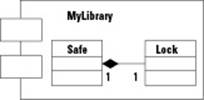
Therefore, you can think of a component as a generic way to group classes together. Figure 3-6 shows a component. It’s a box with a couple added little boxes to its left. Inside this component called MyLibrary, you can see that we put two classes, one called Safe and one called Lock.
Figure 3-6: A component is a box with two smaller boxes added to its left.
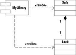
UML provides another way to notate components, which we have shown in Figure 3-7. Notice here that we drew the classes outside the component, and instead pointed dotted arrows at them from the component. We also put the word reside in double angle brackets. (These double angle brackets are actually called guillemots, and the French use them in place of double-quotes. Write it down in case somebody quizzes you on it.)
Stereotyping
Most people accept that stereotyping is a bad thing, but in UML it’s actually a good thing. In UML, you can take an existing symbol, such as the component symbol, and slightly modify it to make your own customized version of the symbol. This modification process is called stereotyping.When you do so, you add a word inside the top of the component symbol. You put the word in double angle brackets. << and >>. (Guillemots again! One for everybody!) In fact, in UML, anytime you see a word in guillemots, you’re seeing a stereotype. Just think of a stereotype as a modified form of the symbol, or your own version of the symbol.
Figure 3-7:Another way to notate components is to use dotted arrows that point the classes to the component.
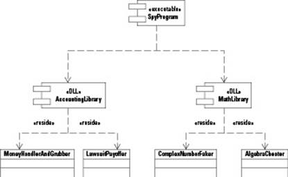
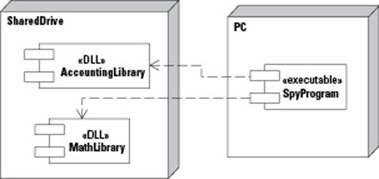
When you create a component diagram, you can use stereotypes in your components. Think of it this way: Suppose you have several components that you are going to build into a DLL. Because the component symbol itself doesn’t have any place to notate that it’s a DLL, you can create your own DLL component symbol. You do this by putting a stereotype inside the component symbol. Figure 3-8 shows three components all working together. Two will ultimately be DLLs, and one will be the final executable file that calls into the DLLs. To show these, we stereotyped them all. Notice that because we’re creating our own symbol, we can reuse the symbol. In this case, we used the DLL component symbol twice. If we have more executables, we can also reuse the executable component symbol.
CASE tools differ on how you add stereotypes. With many tools, you use a menu item; and in a dialog box that opens, you add a name for the stereotype. Then you choose the base class. Now don’t confuse that with what you normally think of as a base class. We’re talking about metainformation here. Look at it this way: You have a symbol, such as component. Now you’re making your own specialized symbol based on component, called, for example, DLL component. This DLL component is, in a sense, derived from the component symbol. Thus, the base class in this hierarchy is the component symbol. And so, when you create a stereotype for a component, the base class is component.
Before you make your own stereotype, first check to see whether it already exists. Many stereotypes are already available in UML. For example, in the CASE tool that we’re using, executable already exists for the component symbol.
In Figure 3-8, you can see how we used stereotypes to create a special DLL component symbol and a special executable component symbol. Notice also that we drew an arrow from the executable called SpyProgram to the two DLLs, called AccountingLibrary andMathLibrary. These arrows are dashed and have no stereotype with them. The dashed arrows mean that they depend on the two libraries. Meanwhile, the two libraries each have two classes in them. To show that the classes reside in the libraries, we used a dependency arrow (again, a dashed line), but we used stereotypes to show that these are reside forms of the dependencies. So again, this is a special version of the symbol, which we denote through stereotypes.
Figure 3-8: You can use stereotypes and show different components working together.
Deploying the Software
During your designs, you can create a diagram that shows how your software will run and will be configured on the final computer system. In UML, the diagram you use is called a deployment diagram. This is a static diagram because the information in it does not change while the program is running.
Figure 3-9 shows an example of a deployment diagram. In this figure, we included two nodes. In a hardware system, a node is any computer component. In this case, one node is a PC, and the other node is some shared drive on the network. You can see in the diagram that the shared drive contains the two DLLs. The executable itself, however, resides on the user’s PC. Note also that the components have connections between them because we used the same CASE model that we used in Figure 3-8. When we added the components to the two nodes, the CASE tool automatically drew the lines to connect them.
Figure 3-9: This deployment diagram has two modes.
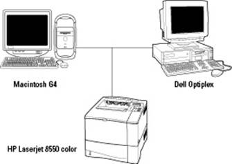
One particularly fun thing about deployment diagrams is that the UML standard lets you make your own versions of the symbols. However, this creative capability goes beyond just stereotyping, where you add a word inside those funny angle brackets. Instead, you can actually use clip art! Yes, clip art! Take a peek at Figure 3-10 to see an example.
Figure 3-10: You can be creative when designing your deployment diagrams!
All materials on the site are licensed Creative Commons Attribution-Sharealike 3.0 Unported CC BY-SA 3.0 & GNU Free Documentation License (GFDL)
If you are the copyright holder of any material contained on our site and intend to remove it, please contact our site administrator for approval.
© 2016-2026 All site design rights belong to S.Y.A.