Make: 3D Printing (2014)
Part III. 3D Scanning
Chapter 6. Creating and Repairing 3D Scans
Use the Kinect, ReconstructMe, and 123D Catch to capture 3D models of real world objects—then clean them up for 3D printing.
Anna Kaziunas France
Excerpted from Getting Started with MakerBot by Bre Pettis, Anna Kaziunas France, and Jay Shergill.
This is all experimental. There is no “way.”
— Bre Pettis
You no longer need an expensive high-end 3D scanner to create good-quality scans that are suitable for 3D printing. There are now an increasing a number of affordable ways to digitize physical objects. Some of them require additional hardware with an RGB camera and depth sensors, like a Microsoft Kinect or an ASUS Xtion shown in Figure 6-1 (see Kinect vs. Asus Xtion for a comparison), but you can also use your phone or a digital camera to capture images. These images can then be converted into 3D models, cleaned up using mesh repairing software, and then printed.
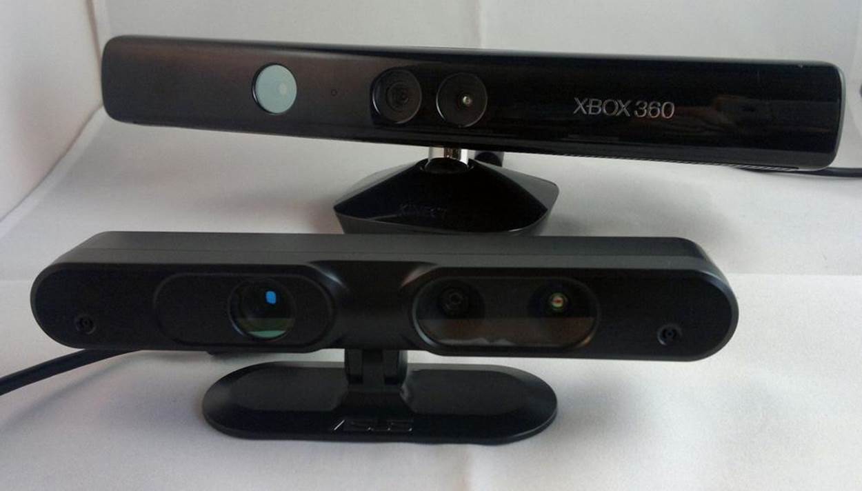
Figure 6-1. The Microsoft Kinect and ASUS Xtion
KINECT VS. ASUS XTION
As soon as the community cracked open the Kinect and made it do things it wasn’t intended to do, 3D scanning was one of the first items on the list. As wonderful and disruptive as the Kinect was, it wasn’t the only device of its kind. In fact, other folks brought the exact same technology to market. Scanning with the Kinect is powered by hardware developed by an Israeli company, PrimeSense. PrimeSense released a software development kit (SDK) called OpenNI (Open Natural Interaction) that some people, such as the folks behind ReconstructMe (PROFACTOR GmbH), have used to develop awesome software tools for Kinect. And the great thing about this is that their software can be made to work with other hardware that uses the PrimeSense technology.
One such piece of hardware is the ASUS Xtion ($160), which has some advantages over the Kinect:
1. It is much smaller (about half the size).
2. It’s lighter (half a pound).
3. It doesn’t require a separate power supply (it can be powered over the USB connection).
The Xtion has some disadvantages, though:
1. It’s more expensive.
2. It does not work with all software written for the Kinect.
3. It doesn’t have a software-controlled motor (the Kinect has one you can use for moving the camera around).
Still, if you’re looking for a portable depth camera for 3D scanning, the Xtion is well worth considering.
What Is 3D Scanning?
A 3D scanner collects data from the surface of an object and creates a 3D representation of it. The Kinect and Xtion both work by beaming infrared light at an object, and measuring how far away each reflected point of light is. It then turns each individual point into a collection of points called a point cloud (Figure 6-2). Each point in the cloud is represented with an x, y, and z coordinate.
This point cloud is processed (or reconstructed) using scanning software into a digitized representation of the object known as a mesh (Figure 6-3). A mesh is similar to a point cloud, but instead of only using single points (or vertices), it groups each vertex with edges (straight line segments) that combine to form faces (flat surfaces enclosed by edges) that describe the shape of a 3D object. STL files are comprised of these triangular meshes.
123D Catch works by analyzing a group (twenty to forty) of images of an object taken from different angles. (The analysis for 123D Catch is performed in Autodesk’s cloud-based systems.) By performing image analysis on the photos, 123D Catch is able to isolate an object in the photos and create a 3D mesh from the collection of photos.
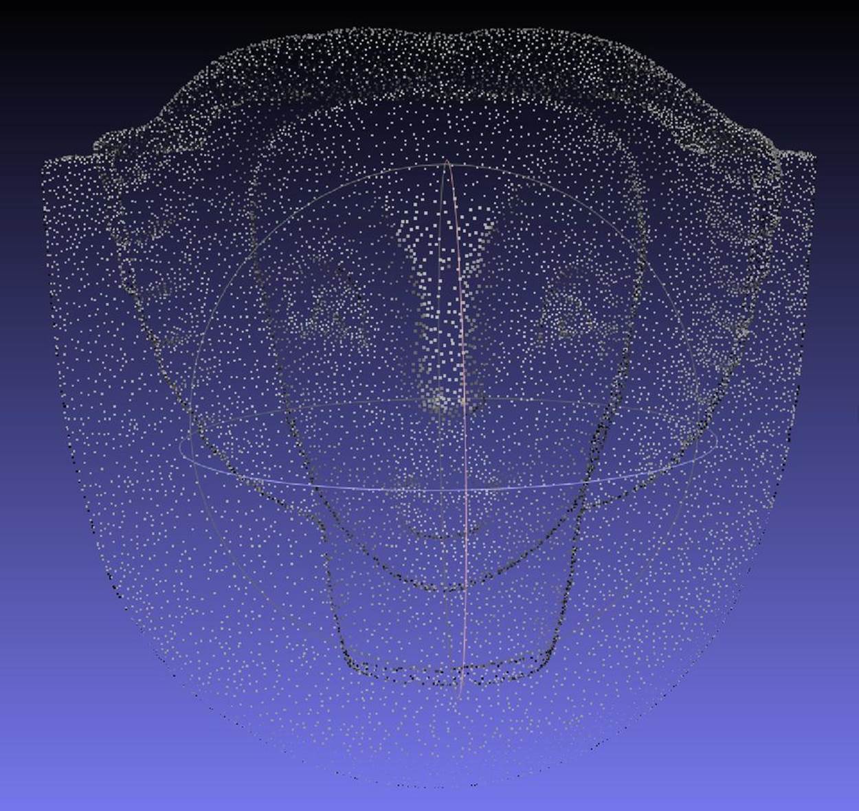
Figure 6-2. A point cloud
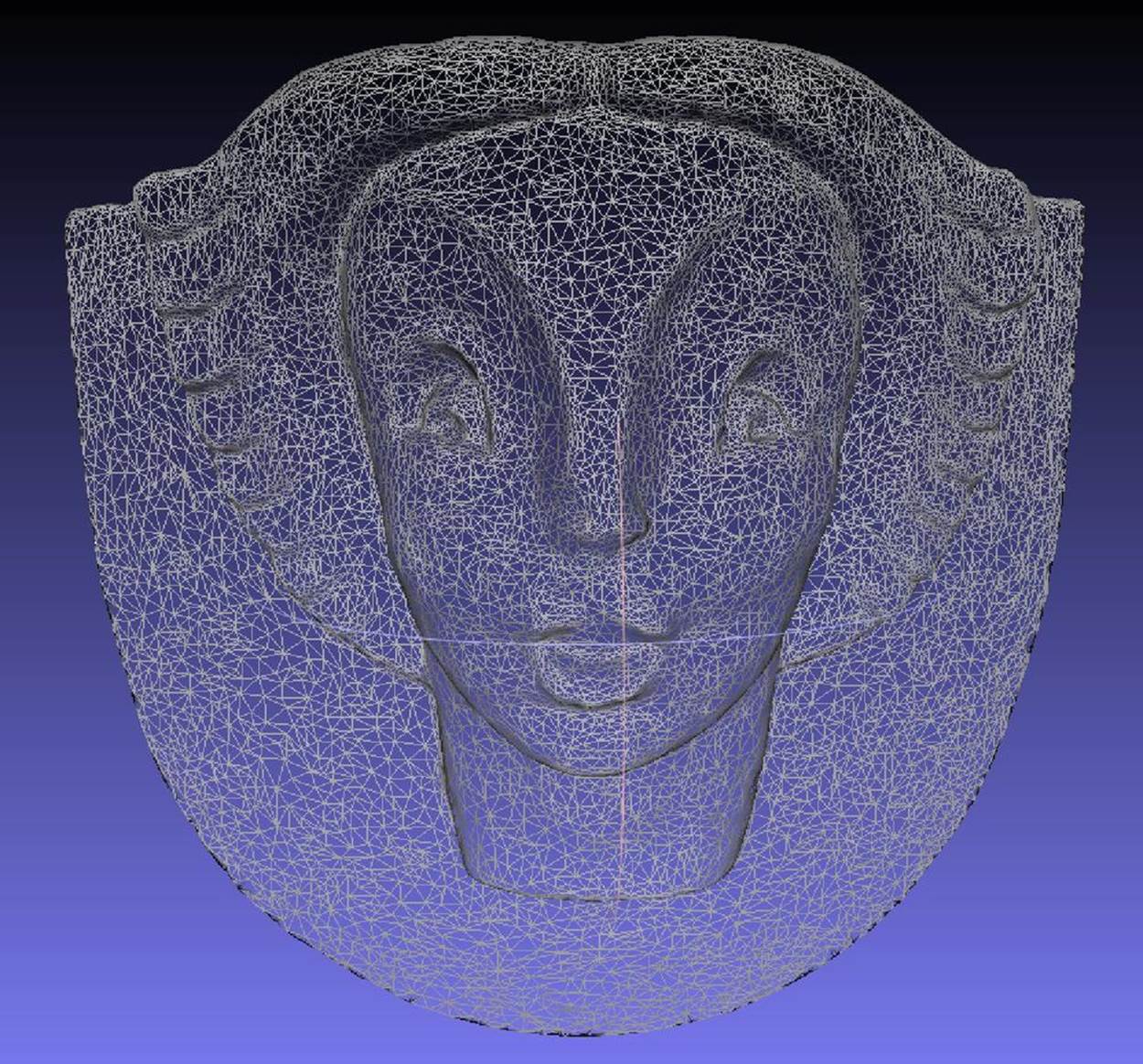
Figure 6-3. A mesh
Limitations
The limitations of 3D scanning depend on what technology is being used. For example, optical scanners have trouble scanning transparent or shiny objects, and digitizing probes can only scan the top surface of an object. All the software programs discussed here also have strengths and weaknesses.
What software you use to scan your model depends on the size of the model and your computer’s hardware configuration. Two popular applications are 123D Catch and ReconstructMe. This chapter tells you how to use both of these. Each of these scanning packages has its own set of advantages and limitations.
In the past you needed to use a high-end scanner and expensive software, but thanks to these free programs, you no longer need to spend big bucks to get printable scans.
123D Catch
123D Catch is a free application from Autodesk that enables you to take photos and turn them into 3D models. It is available as a web-based application, an app for the iPad and the iPhone, and a desktop application for Windows. It works by taking multiple digital photos that have been shot around a stationary object and submitting those photos to a cloud-based server for processing. The cloud server uses its superior processing power to stitch together your photos into a 3D model and then sends the model back to you for editing. You can download or access 123D Catch at http://www.123dapp.com/catch.
123D Catch Tips
The quality of the scan that you receive from 123D Catch is dependent on the quality and consistency of the photos you provide. Here are some general tips on how to select objects to Catch and how to plan out your Catch so that you obtain desirable results:
Objects to avoid
When choosing objects to scan using 123D Catch, avoid reflective surfaces (Figure 6-4), objects with glare, and mirrored or transparent surfaces. These objects will not work well for generating 3D models. For example, windows that are reflecting light will appear warped or bowed, like funhouse mirrors. Transparent objects like eyeglasses will appear as holes in the model.

Figure 6-4. Avoid shiny objects—they will not Catch well
Plan of attack
Before you start a capture project, plan out the order in which you will take your photos. It is also important to decide on a focal length. If possible, position the object that you want to Catch on a table that you can move around easily and remain equidistant from the object at all angles. Planning out how you will approach your subject is the key to success when using 123D Catch.
Mark your territory
Consider using some sort of marking system when your subject lacks discernible features or is highly symmetrical. 123D Catch has trouble with symmetrical objects, and markers will help the application to register different sides of the object. You will need four points for registration between any one image and two other images in the collection. Consider placing high-contrast tape or sticky notes on a large object. Place enough markers so that at least four are always visible from any of the positions you plan to shoot from.
Utilize background objects
When possible, utilize background objects around the object you are capturing. This will help the software parse depth. 123D Catch does not like a blank wall background with flat paint. Do not attempt to Catch objects on a flat colored surface, like a white tablecloth. You will get better results by using a background with patterns (Figure 6-5) that help the 123D Catch software clearly differentiate between the object you are attempting to capture and the surface it is resting on.
Figure 6-5. Use a contrasting background
What kind of camera?
Point-and-shoot cameras, like those in a regular digital camera, phone camera, or the camera in an iPad of 3 megapixels or higher will work well. We have been getting great Catches using an iPhone 4S.
Watch the Autodesk 123D Catch tutorials
Additional tips on using the 123D Catch software are available here: http://www.123dapp.com/howto/catch.
Taking Photos with 123D Catch
Your first step after planning out your project is to methodically take pictures of the object you want to Catch. Here are some tips:
Provide enough information
You will need to provide enough information with your pictures for the reconstruction software to create a model. Rotate around your object, capturing a frame every 5-10 degrees (Figure 6-6). The goal is to get least 50% overlap between images. Move the camera at regular intervals and in a predictable pattern (from left to right and from top to bottom). Make sure each point in your object is appearing in at least four shots. When your photos do not have enough information, your scan may have a solid mass where there should be empty space or a gaping hole where there should be mesh.
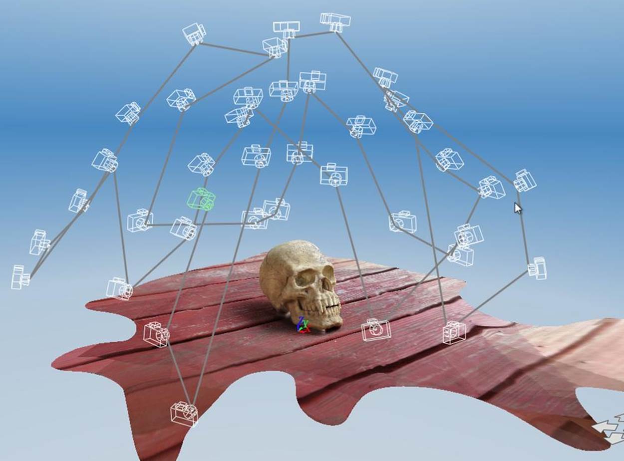
Figure 6-6. Take photos every 5-10 degrees around the object
Fill the frame
Try to fill the camera frame with your image (Figure 6-7). It is helpful to work consistently from high to low, and from left to right. This will help you to identify errors (should they occur) later, after the models are created. Once you start capturing frames, avoid zooming in or out. Zooming distorts your capture and may make it impossible for the application to align your set of images.
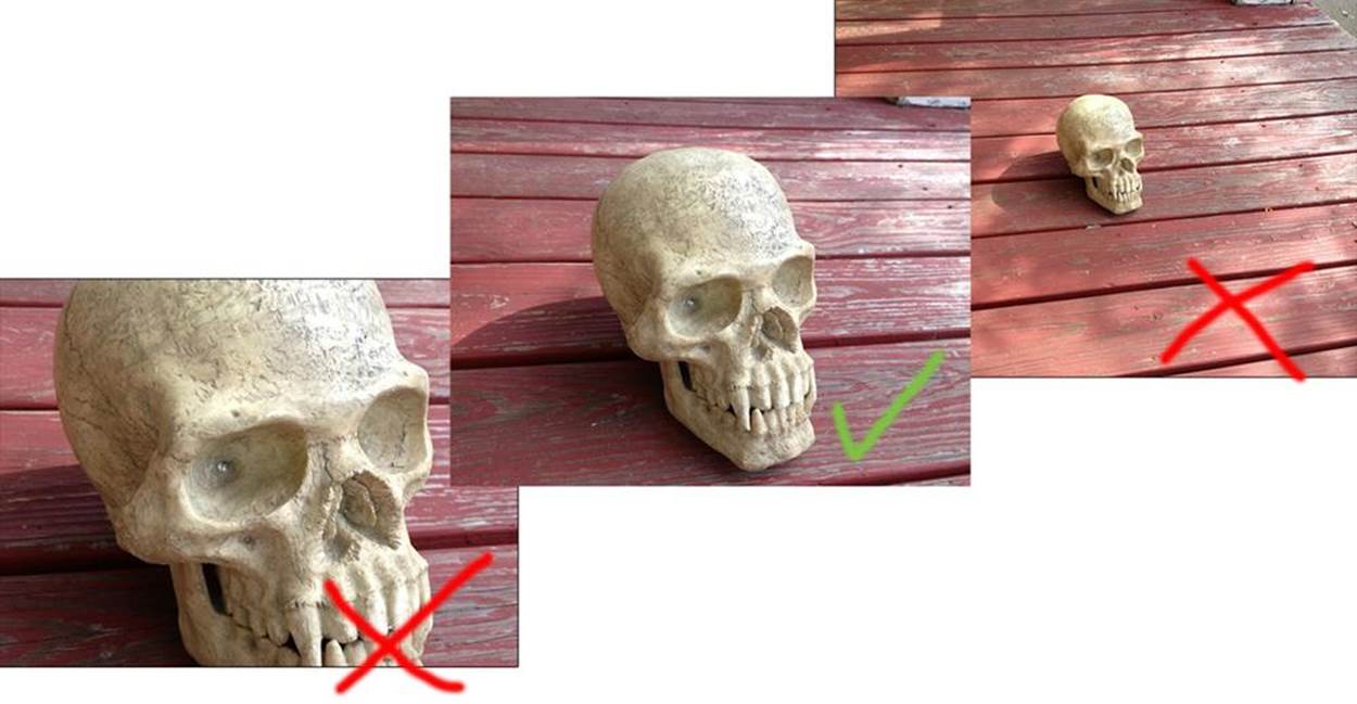
Figure 6-7. Right way—image fills the frame
Uniform light
Make sure there is uniform light around the thing you’re trying to Catch. Avoid overexposed or underexposed images, as they hide the features you are trying to capture.
Direct light alters the exposure by creating shadows and reflective spots. The more consistent the exposure of the photographs is, the more consistent your model will be. We found that many of our best Catches were shot on overcast days or at dusk. Consider planning your outdoor Catches around these light conditions for best results.
Maintain depth of field, focus, and orientation
Blurry images will not produce accurate Catches. Review your images before leaving the scene of the Catch, and if any of them are blurry, retake the images before submitting the photos for processing. On the iPhone/iPad, you can review and retake images before submitting them for processing. If you are using a digital camera, make sure to review your images before leaving the scene of the Catch.
In addition, your images must have a consistent depth of field. If you are focused on the item you are Catching and the background is blurry in your photos, keep this consistent throughout the shoot. Also keep the orientation of the photos consistent. Choose either portrait or landscape and stick to it.
How many pictures?
More pictures are not necessarily better. What is important is the regular intervals and the capture of the overlapping angles of the object. Many pictures will take much longer to process, and if they are not capturing the object uniformly they will still produce poor results. The optimal number of pictures has been reported as somewhere between 20 and 55 pictures, depending on the object. If you are using the iPad or iPhone you are limited to 40 images.
Capturing detail
If you need to capture fine details, first capture the entire object at a distance that fills the frame. After you have completed a full sweep of the entire object, then move in and capture the details. Make sure that you maintain the 50% overlap between the distance photos and the detail photos, so that the software can still stitch the photos together. Be careful when transitioning from shots of the whole model to detail shots. Make sure to have transition photos that capture 50% overlap between the transitions. Do not suddenly zoom in on the detail, as this will either cause your scan to fail or produce poor results.
By taking a whole series of close up pictures just at one level, I got really good 3D detail. Really good reproduction of very, very small depth.
— Michael Curry “skimbal”
With some large objects, like statues, it may not be possible to get both very fine detail and the entire object. You may need to capture the fine detail in a separate Catch. You will need to experiment. Occasionally, we have had catches done this way completely fail on the iPhone application, and a large white X will appear after processing the Catch. Because it can take some time to see how your Catch turned out, always do one or two Catches of an object (especially if you are on a trip and may not return to it), just in case the first one fails. If your Catch fails, consider capturing the entire object in one scan and then creating a new scan with the camera zoomed in on the fine detail.
Don’t be discouraged if your first few Catches do not come out as planned; keep practicing and you will quickly get a feel for the process and how to minimize problems.
Do not edit or crop photos before uploading! Any size, color, or tone alterations will confuse the reconstruction software and lead to less than optimal results. Upload your photos to the cloud server as they were originally taken.
Uploading Your Photos to the Cloud
Take your photos using the process outlined above and then submit them to 123D Catch via your application of choice.
If you used the iPhone or iPad application
Submit the photos via the iPhone/iPad app (Figure 6-8). The app will inform you when it has finished processing your 123D Catch scan, or photoscene.
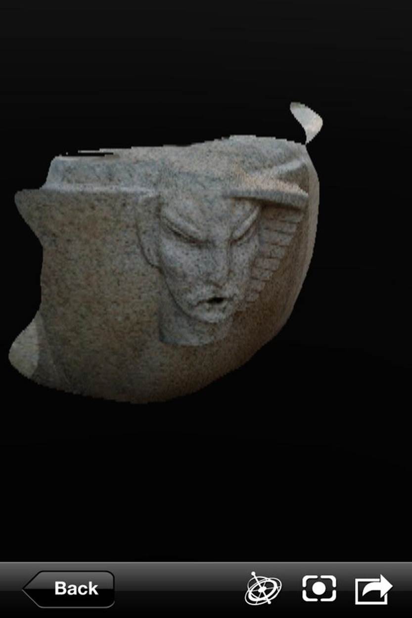
Figure 6-8. Completed photoscene on the iPhone
If you are using the Windows desktop application
Download your photos onto your computer. Then open 123D Catch and select “Create a New Capture.” A login window will open and you will need to log into your Autodesk account (or create one).
If you are using a camera and do not have Windows
Download your photos onto your computer. Then go to http://apps.123dapp.com/catch to upload them. It can take some time for the 123D Catch cloud server to process your photos, but you don’t have to wait around. Your Catch photoscene will appear in the “models” section of you account when it is finished.
When uploading images using the Windows desktop or online application, you can select all of your images and upload them at once. You do not need to upload them one at a time.
Downloading Your Mesh
After your photoscene is available, you need to retrieve the file in an editable format.
After the photos have been processed, and log into your account. Regardless of the method used to upload your photos, your processed scans will be present under “models & projects.”
Click on a model to open it. Then download a STL file for printing at home or you can edit your model online using 123D apps.
The STL will often be named viewable.stl.
There are editing tools in the online and desktop versions of 123D Catch that you can use to slice off sections to prepare models for 3D printing in both the online and desktop versions, although the online version is more up-to-date and has better tools. You can also edit your mesh using the techniques described in Cleaning and Repairing Scans for 3D Printing.
ReconstructMe
ReconstructMe is a 3D reconstruction system that gives you visual feedback as you scan a complete 3D model in real time. It works with the Microsoft Kinect (Xbox and PC versions) and the Asus Xtion Pro. Currently there is both a free/noncommercial version and a paid, commercial version of the software. ReconstructMe is excellent for scanning larger objects, such as people, but not great for small objects with fine detail.
ReconstructMe is currently the easiest way to get quick and complete scans, but there are a few unavoidable technical limitations that come with this type of real-time scanning. First, ReconstructMe is Windows-only, but it can be run cross-platform using virtual machines or Boot Camp on a Mac. You also need a fairly high-end graphics card to run the software. It is also picky about the version of OpenCL (a computer library that can run instructions on your graphics adapter) installed on your machine. ReconstructMe is constantly being updated, so refer to the ReconstructMe documentation and video card specifications.
ReconstructMe QT is a graphical user interface alternative to the ReconstructMe console application. It uses the ReconstructMe SDK and is available in both free non-commercial and paid versions.
Installing ReconstructMe
Download ReconstructMe
Go to this download page and download either free Lite version the free developer version.
INSTALLING RECONSTRUCTME ON A MAC WITH A VIRTUAL MACHINE
You can install ReconstructMe on a Mac without using Boot Camp by running Windows on a Parallels or VMware Fusion virtual machine in the same way you would install it on Windows, with one exception. You will not be able to upgrade your graphics driver for the virtual machine by downloading an update from the manufacturer. You will need to install OpenCL support separately. You can get the OpenCL CPU runtime for Windows from Intel here: http://software.intel.com/en-us/vcsource/tools/opencl-sdk.
If you go this route, you won’t be able to perform a live scan. Instead, you’ll need to first record your subject with the ReconstructMe Record tool, then complete the scan with ReconstructMe Replay.
Installing ReconstructMe on virtual machines is experimental and your mileage may vary.
Tips for Reconstructing Yourself (or Someone Else)
Once you have ReconstructMe installed, refer to the ReconstructMe website to learn how to launch the application. There are several different resolutions and modes available for scanning with ReconstructMe, and new features are being added all the time.
If you experience crashes in both the standard and highres modes, you may need to run the ReconstructMe Record tool. After saving your scan, you can play back the recording with ReconstructMe Replay and save your file as an STL.
When you have ReconstructMe up and running on your machine, here are some basic tips for scanning yourself (or someone else).
1. Sit in a spinnable office chair.
2. Position your Kinect or Xtion so that only your upper body is visible in the scan area.
3. Slowly, spin yourself around in the chair while keeping your upper body in a static position.
4. Save the file as an STL (make sure to do this after you finish your capture, while the console is open, or you will lose your scan).
5. If your graphics card or memory constraints are causing the program to crash, try using the Record feature to record your scan and then playback to reconstruct the mesh.
When scanning yourself, sit with your back to the Kinect/Xtion with your computer in front of you. That way your arm movements will not be captured when you press the keys on your computer to start and end the scan.
After saving the STL, open it up in MeshLab or Pleasant3D and take a good look at it. Figure 6-9 shows a scan of Anna.
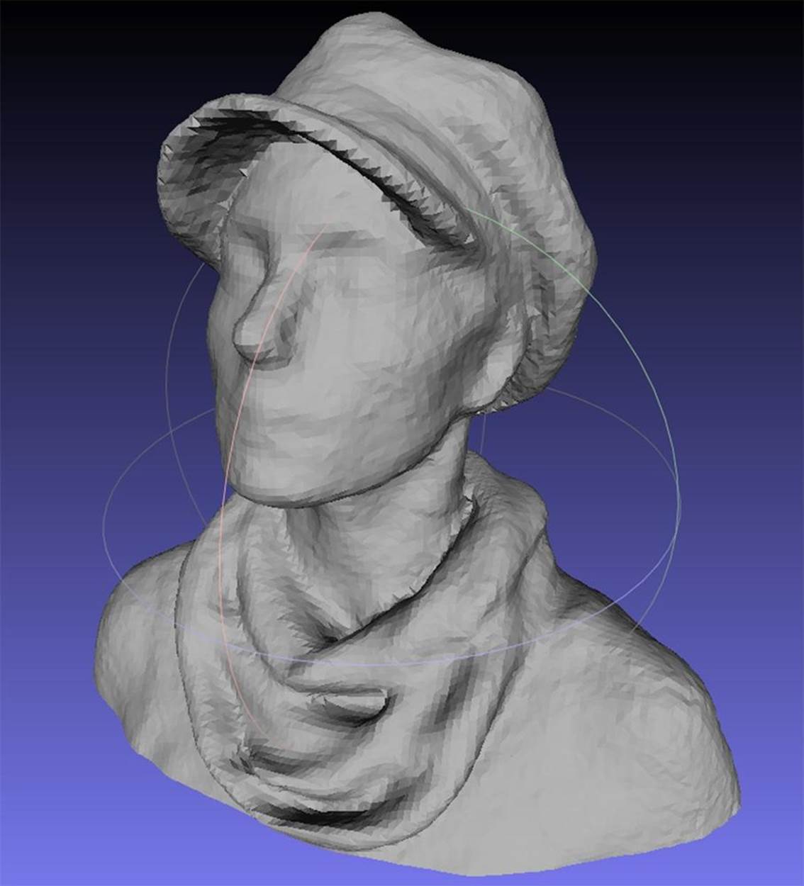
Figure 6-9. Scan of Anna Kaziunas France
All the ReconstructMe scans in this chapter were done using Boot Camp on a mid-2010, 15-inch MacBook Pro running OS X 10.8.1 (Mountain Lion) with a 2.66 GHz Intel Core i7 processor and 8 GB of memory. The graphics card used was an NVIDIA GeForce GT 330M 512 MB. With this configuration, we were able to run real-time reconstruction mode but unable to run the high-resolution setting for ReconstructMe. The lack of definition in the facial features in the scan reflects these constraints. However, ReconstructMe is excellent at capturing folds in fabric, so Anna wore a hat and scarf during the scan to make up for the lack of facial definition. Other smooth fabric items, like shirt collars, ties, and smooth hair, are also captured well.
GET A HANDLE ON IT!
If you are scanning other people or things, a Kinect handle (like this) or a Kinect tripod mount (or such as this) can come in handy (see Figure 6-10).
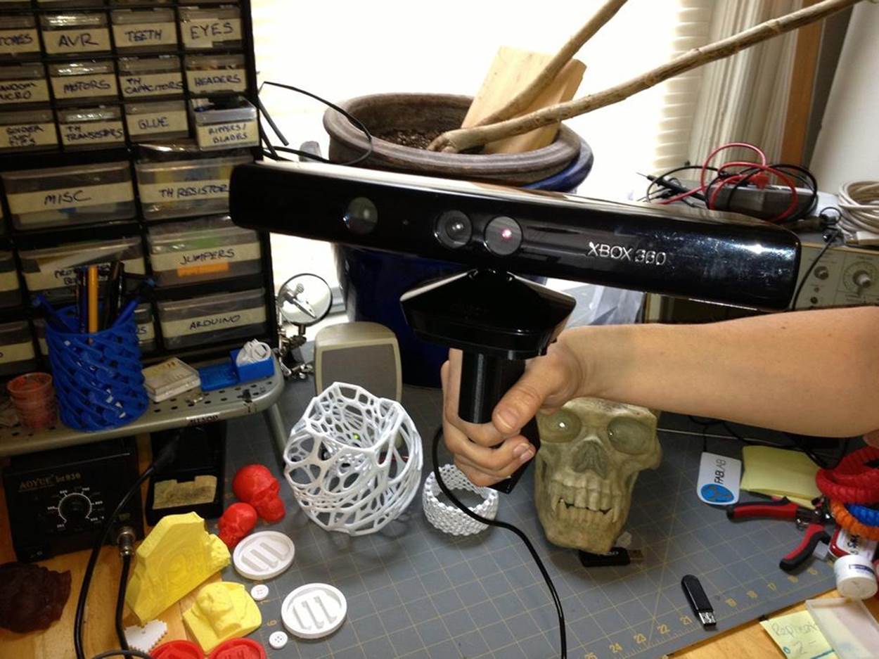
Figure 6-10. Kinect on a handle
Cleaning and Repairing Scans for 3D Printing
While it is becoming easier to create high-quality scans, creating valid input files is sometimes difficult. Before you can print your 3D scans, you need to clean up, edit, and repair the files to make them printable.
The most common problems with 3D scans are:
§ Holes
§ Disconnected parts
§ “Junk” from the environment around the model or used to map the object in space that is not part of the model
§ Open objects with faces that are not closed
However, analyzing STL files for errors and buildability has never been easier. Each of the following software packages has strengths that when used together, can make it easy to edit and print great looking scans.
Tony Buser created the seminal video tutorial on cleaning and repairing 3D scans that deeply informed this chapter (you can watch here).
Tony had also created an new updated video with a streamlined scanning cleanup workflow (here).
netfabb
netfabb (Figure 6-11) enables you to view and edit meshes and provides excellent repair and analysis capabilities for your STL files. netfabb makes it easy to slice off bits of jagged scans and quickly repair those scans. In most cases, you will want to slice off the bottom of your model to create a flat surface against the build platform.
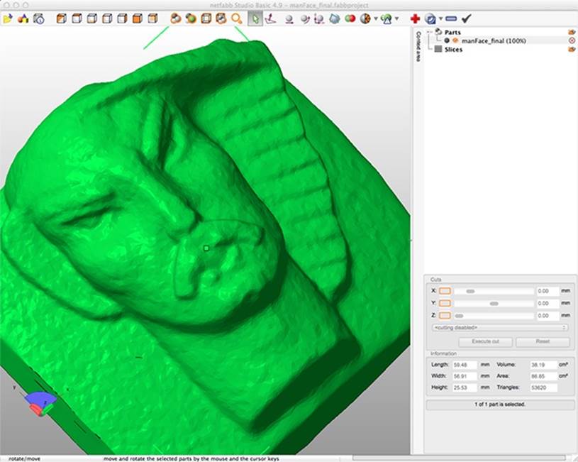
Figure 6-11. 123D Catch scan of a stone face, shown in netfabb
netfabb is available as a desktop application and a cloud service. It is also available as an STL viewer with connection to the cloud service on the iPhone. netfabb Studio is available in both Professional and (free) Basic editions. It runs on Windows, Linux, or Mac.
Autodesk MeshMixer
MeshMixer is great for mashing up individual meshes together into a new model (Figure 6-12). It works well for smoothing out bumps, blobs, and other strange artifacts that can show up in scanned files. It is also an excellent tool for capping models that are missing a side/top/bottom to make them manifold.
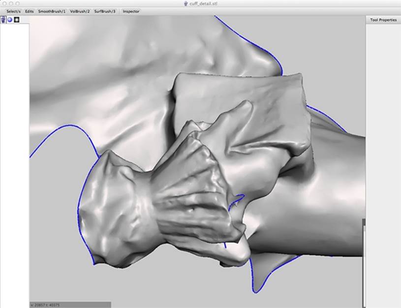
Figure 6-12. 123D Catch scan of a statue, shown in MeshMixer
MeshLab
MeshLab can repair and edit meshes, but its Poisson filter is great for smoothing surfaces to clean up scans for printing (Figure 6-13). It’s easy to rotate meshes with the mouse, so it also is an excellent STL viewer. It is available as a cross-platform desktop application and as a model viewer for iOS and Android. See also Smoothing Out the Surface of Meshes.
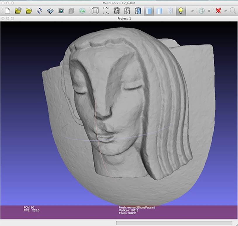
Figure 6-13. 123D Catch scan of a stone face, shown in MeshLab
Pleasant3D
Pleasant3D, shown in Figure 6-14, is a great Mac-only application for previewing and resizing STL files by specified units (as opposed to scaling in MakerWare). It can also convert ASCII STL files into binary STL. It shows G-code visualizations, which let you preview how your model will print.
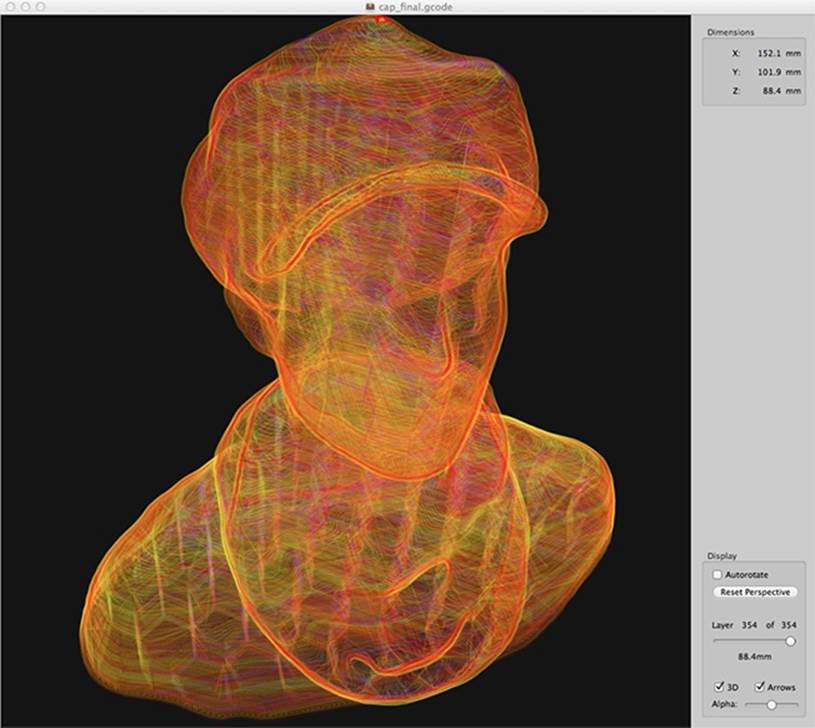
Figure 6-14. G-code visualization in Pleasant3D
Repairing Most Scans
Most scans you create using these software programs will have a mesh that is mostly complete. However, these scans will usually have holes, junk, and other issues that you will need to fix. If your scan is missing large areas of mesh and has huge gaping holes, or is just the front or relief of a building or sculpture, see Repairing Relief Scans by Capping. To find out how to repair more minor issues, read on.
Repair and Clean Up in netfabb
Open netfabb Studio Basic and open the STL file of the model with Project→Open. (See Figure 6-15.)
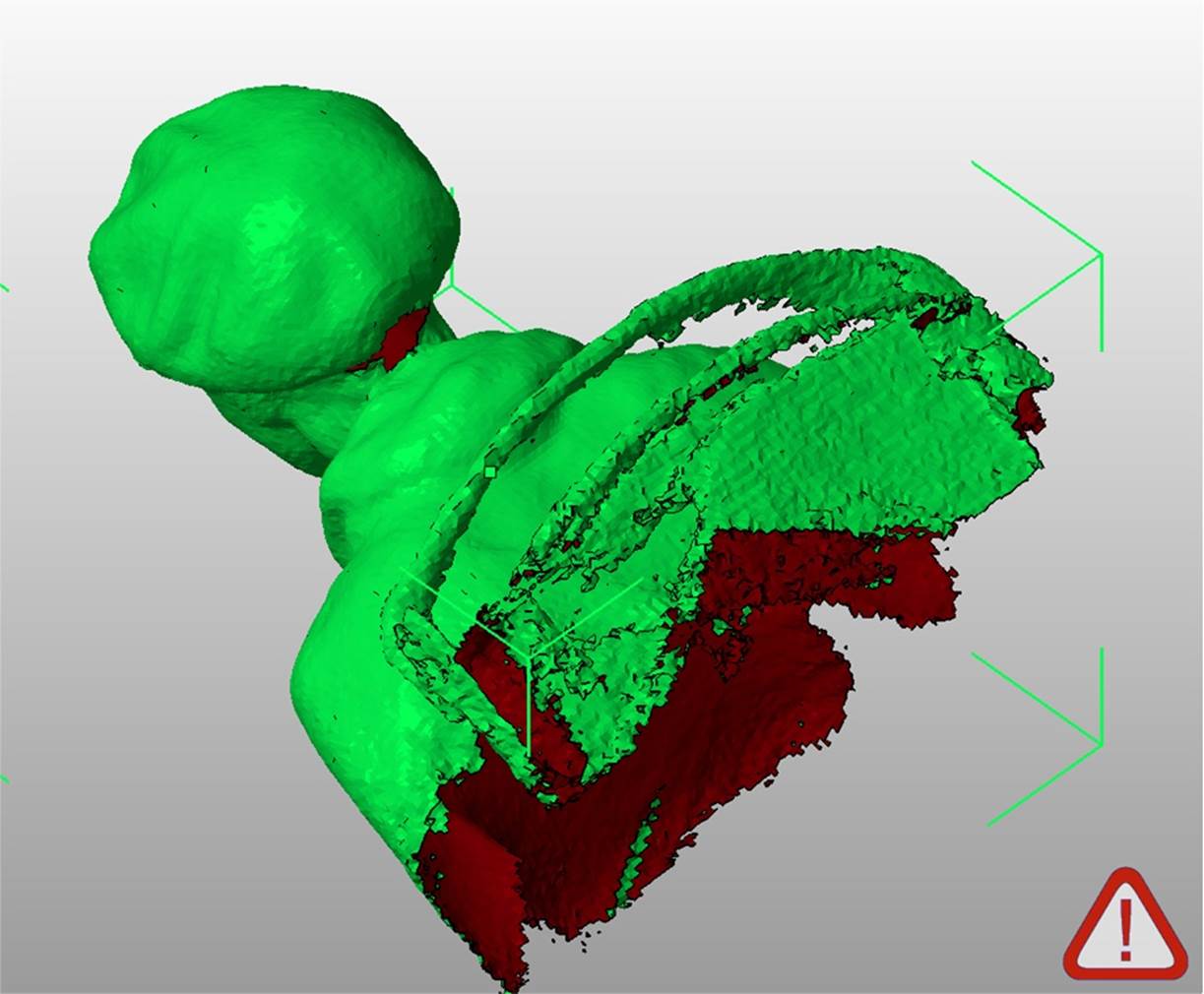
Figure 6-15. ReconstructMe scan opened in netfabb
To repair and clean up the model, follow these steps:
Show the platform
To help you see your model’s orientation, select View→Show Platform. If you can’t see the yellow platform, then you may need to zoom out.
Reorient the model
To move the part to the origin of the platform, select Part→Move, then select the To Origin button from the dialog box and click Move.
Now zoom in on your model by selecting View→Zoom To→All Parts.
Click the selection tool (the arrow). Click the model to select it, then move the selection tool over the green corner that appears around the selected model.
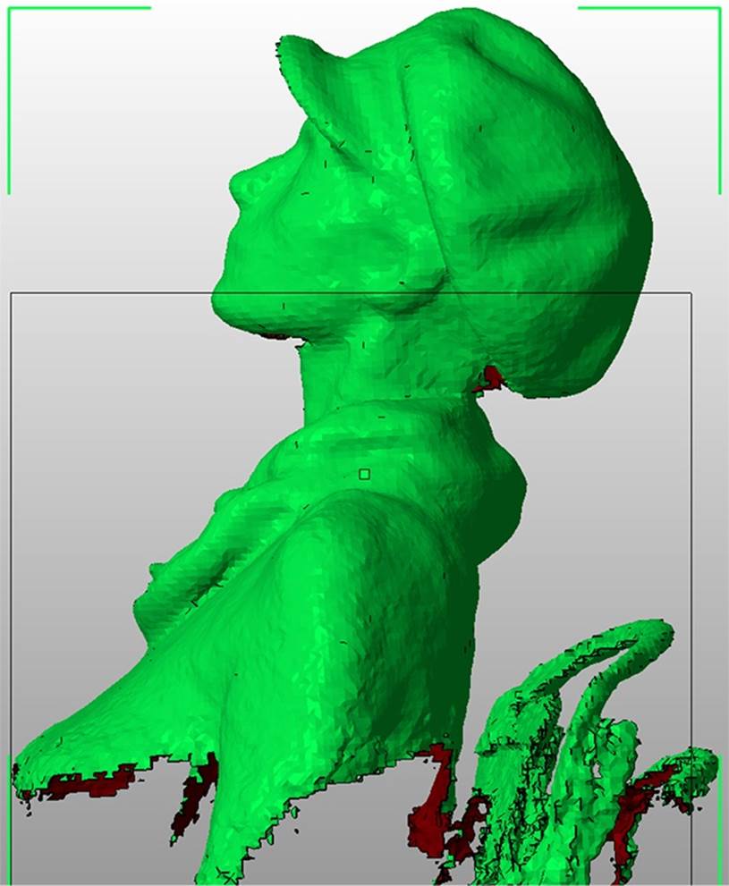
When the selection tool is over the green corner bracket, it will appear as a rotation symbol. Rotate the model, tilting it so the head is pointing up and the body is pointing down towards the platform, as shown in Figure 6-16.
To pan in netfabb, hold down Alt and drag the mouse.
Tweak the model alignment
You will have to change your view and rotate the model several times in order to orient it on the platform. Try to place the model so that the shoulders are at equal height.
You can change your view from the View menu or click on the cube faces in the main toolbar at the top of the screen. Align the model within the box relative to the platform.
Make sure to tilt the head back using the rotate tools to help with the overhang that can develop under a person’s chin. (Remember the 45 degree rule from Generating STL files.)

Figure 6-16. Scan reoriented
WATCH YOUR UNDERHANG
The model shown here has a severe chin underhang. Try to minimize this when creating your scan. The back of the head where the hat juts out also has a severe overhang. We used external support material to help print the hat back. The support material did not build under the brim and chin, but it still printed pretty well!
Slice off the jagged bits
Use the Cuts tools on the right of the screen to cut a flat bottom for the model. Drag the Z slider so the bottom of the blue cut line is cutting off the scan’s jagged edges. Click the Execute Cut button, then click Cut.
You can then click on the part of the cut model that you want to remove. The selected part will turn green, as shown in Figure 6-17.
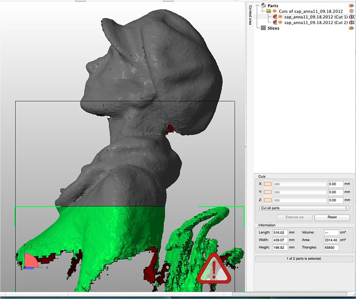
Figure 6-17. Selected section to remove
Remove the jagged section
Go to the Parts section that is now displayed in the top-right corner of the screen. Click the X next to the part you want to remove (the jagged parts of the scan) to delete that part. netfabb will ask you if you really want to remove it. Click OK.
You will now have a nice clean edge at the bottom of your model.
Move to origin
Move the part to the platform by selecting Part→Move, then selecting the To Origin button from the dialog box and clicking Move (see Figure 6-18).
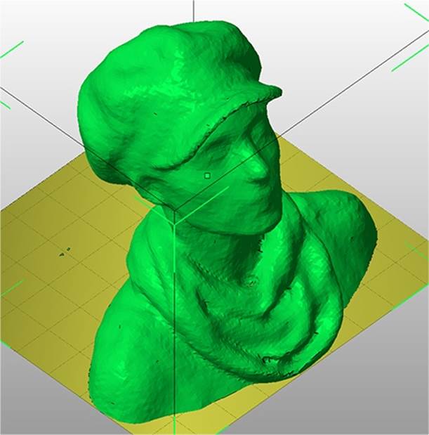
Figure 6-18. The part moved to the platform
Repair the holes
Next, we will repair the holes in the model. There is probably a large hole under the chin where the scanner could not gather information, and possibly a hole in the top of the head.
Select the Repair tool (it looks like a red cross). The model will turn blue and you can see the triangles in the mesh. There will be yellow spots where repairs are necessary. To repair the model, click the Automatic Repair button.
Then select Default Repair from the dialog box and press the Execute button. netfabb will ask you if you want to remove the old part. Click Yes.
Then click the Apply Repair button at the bottom of the righthand side of the screen. In the dialog box that opens, select Yes when asked if you want to remove the old part. Figure 6-19 shows the repaired model.
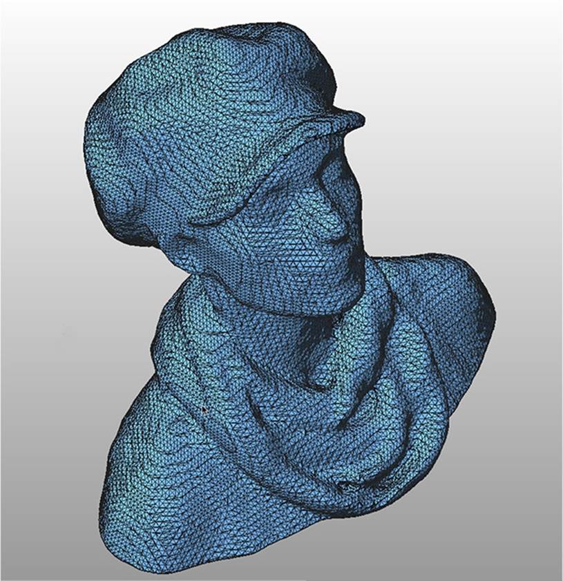
Figure 6-19. Look at all those triangles!
Save in netfabb file format
Save your netfabb project, so you can edit it later (Project→Save As).
Export to STL
Export it as an STL file using Part→Export Part→STL.
netfabb may warn you that there are issues with your file. If you see a big red X when you attempt to export your model, click the Repair button on the dialog box. The X will become a green checkmark.
Then click Export to save the STL.
Smoothing Out the Surface of Meshes
Sometimes you want a smooth surface on a model so it makes a smooth, shiny print. MeshLab’s Poisson filter will smooth out your mesh nicely.
If you are able to create a high-resolution scan from ReconstructMe, you may want to smooth it out a little for printing. For regular resolution, ReconstructMe scans, skip this step to keep more detail in the model.
Open MeshLab
Create a new project using File→New Empty Project.
Then select File→Import Mesh to open your STL file in MeshLab.
When the dialog box pops up that asks you if you want to Unify Duplicated Vertices, click OK.
Turn on layers
Go to the View menu in the top toolbar and select Show Layer Dialog.
Apply the Poisson filter
Select Filters→Point Set→Poisson Filter→Surface Reconstruction Poisson. In the dialog box, set Ochre Depth to 11 (the higher number, the better; “good” is 11). If you go any higher than 11, MeshLab may crash.
Click Apply.
Hide the original mesh
After applying the Poisson filter, there will be two layers: the original (Figure 6-20), and one labeled Poisson Mesh.
Click on the green “eye” icon by the file name to hide the original file and keep the Poisson mesh. You will see visible smoothing on the surface of the model, as shown in Figure 6-21.
Save as an STL file
Go to File→Export Mesh As. Use the default export options.
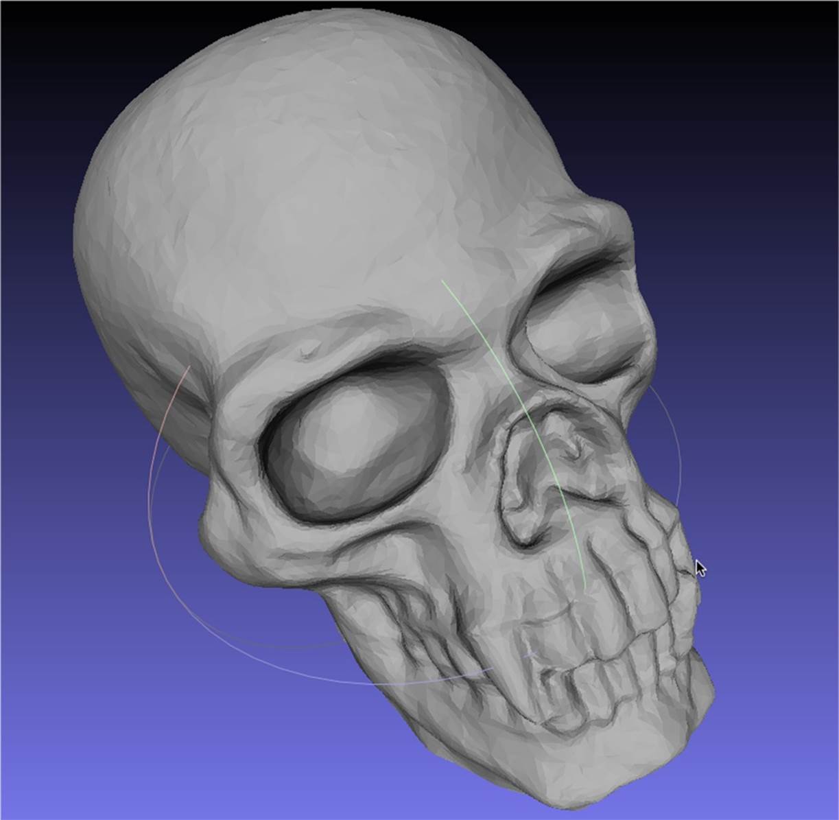
Figure 6-20. Default mesh
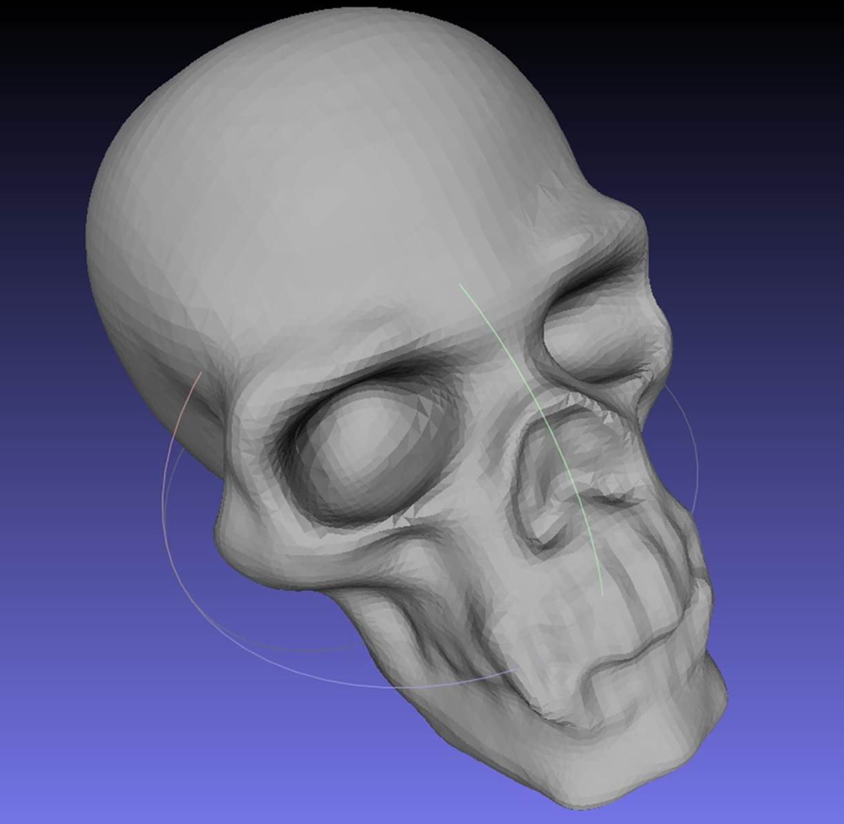
Figure 6-21. Mesh with Poisson filter applied and original mesh hidden
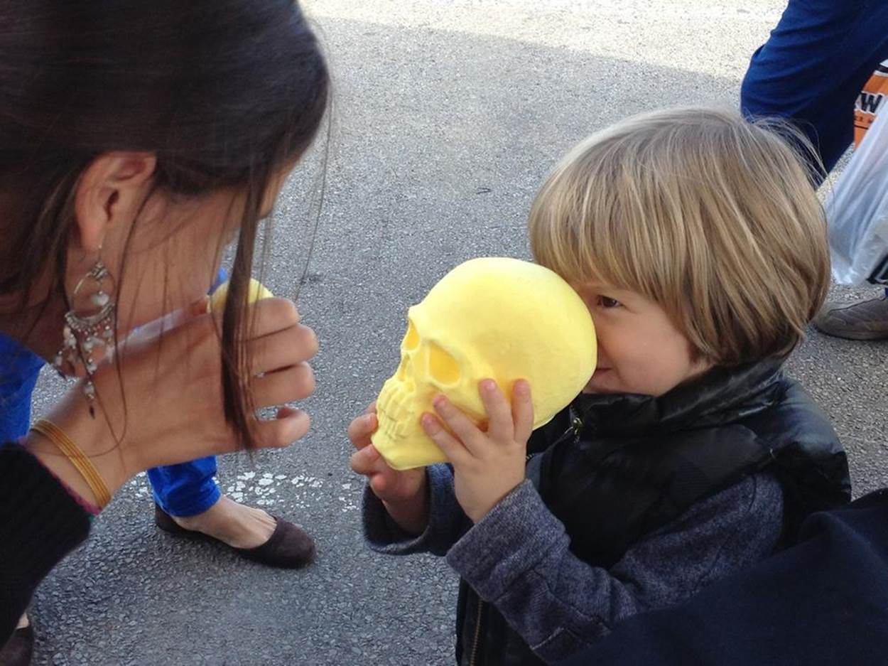
You can see a print of a skull in Figure 6-22.
 New York" width="1250" height="937" />
Figure 6-22. Print of the scanned skull at World Maker Faire New York
Removing Bumps and Blobs with MeshMixer
Depending on how your scan came out after repairing and (optionally) smoothing, you may want to remove some bumps or blobs. If your model does not need any additional smoothing, you can skip this step.
Import your STL
Open up MeshMixer and import your STL file by clicking Import in the top toolbar.
Smooth it out
Select Sculpt → Brushes and one of the “Smoothing Options” from the lefthand navigation bar. Use the sliders to adjust the brush size, strength, depth, and other features.
Click and drag on the bumpy/lumpy areas to smooth them out. When you are satisfied with the appearance, export the file as an STL.
Final Cleanup/Repair in netfabb
Open the STL back up in netfabb.
If you used the Poisson filter in MeshLab, the formerly smooth bottom of your model will be bumpy. To fix this we need to recut the bottom of our model to make it flat. Reslice off the bottom.
Repair the model and export as an STL.
Print Your Model
Your scan is now cleaned, repaired, and ready to print! Open it in MakerWare, then resize or rotate it if necessary and print it out. See Figure 6-23.
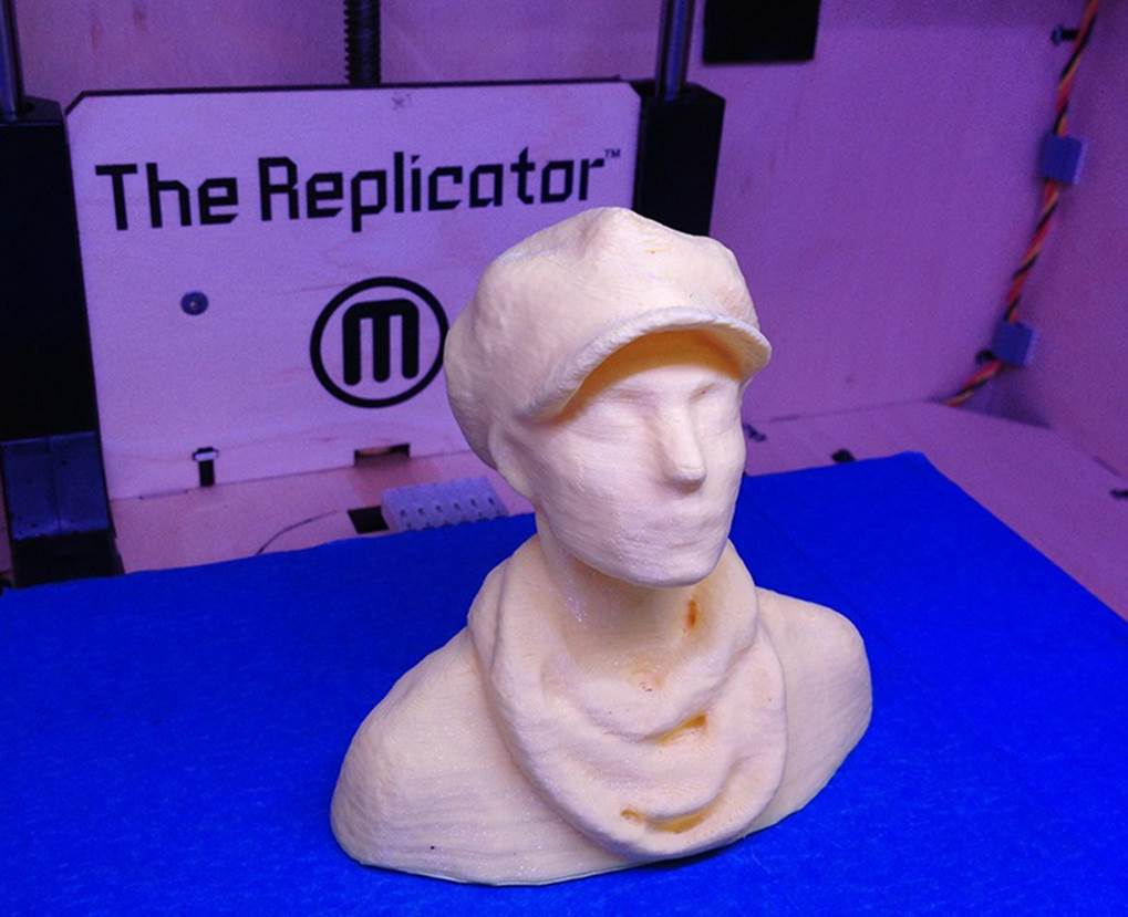
Figure 6-23. Final printed ReconstructMe scan
Repairing Relief Scans by Capping
Sometimes you have a mesh of a building or sculptural relief that is missing a side, top or back and you need to create a closed model by “capping” the object so you can print it. Meshes generated from 123D Catch scans often have these issues when you are only able to scan the front part of a large object. MeshMixer and netfabb can easily help you fix this problem, as well as filling minor holes or removing disconnected parts.
If your model has a lot of extra “junk” in it, it is a good idea to slice it off in netfabb before editing it in MeshMixer. However, sometimes little parts will be impossible to slice off. When this occurs, you can use the lasso tool in MeshMixer to select and delete those stray bits of mesh.
MeshMixer doesn’t have any labeled controls for panning and zooming around your model—you need to hold down the key combinations while dragging with your mouse/trackpad to change your view (see also http://www.meshmixer.com/help/index.html):
Basic MeshMixer view controls include:
§ Alt + left-click: orbit camera around object
§ Alt + right-click: zoom camera
§ Alt + Shift + left-click: pan camera
Fixing Holes, Non-Manifold Areas, and Disconnected Components
When you have a scan that is missing large portions of the mesh, you first need to address the holes, nonmanifold areas, and disconnected components. We will attack each problem in turn.
Open MeshMixer and import your STL or OBJ file (Figure 6-24).
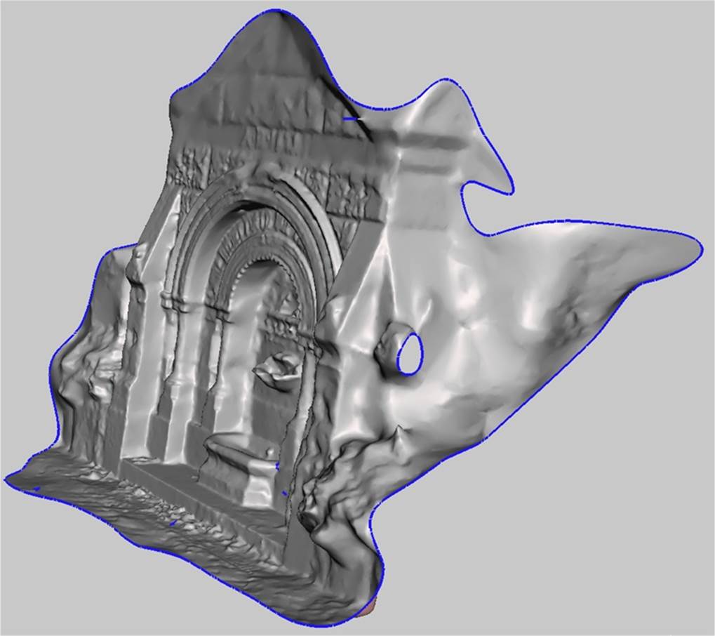
Figure 6-24. Scan opened in MeshMixer
In the side navigation bar, click “Analysis”. Your model will now have a number of colored spheres attached to it, as shown in Figure 6-25:
§ Red spheres represent non-manifold areas.
§ Magenta spheres represent disconnected components.
§ Blue spheres represent holes.
Find the sphere that indicates the large hole
Orbit around your model (Alt + left-click, drag your mouse) to identify which blue sphere is directly on the blue outlined edge that represents the large hole in the model that we want to cap. In the case of the model shown, we want to cap the back of the fountain.
Take note of this particular sphere and make sure that you edit it last. In the case of the fountain model, the sphere that indicates the large hole is circled in the screenshot (see (Figure 6-26). You want to close all of the other minor holes first. Leave the circled sphere for last, we will get to it later when we cap the back of the model.
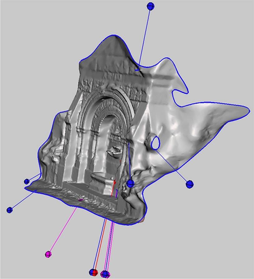
Figure 6-25. Model shown with spheres indicating mesh problems
When repairing meshes with large holes or missing areas, do not click AutoRepair All as this can cause the program to immediately crash. In addition, you want to close the back of the model ourselves to control how it is closed. You don’t want a big autorepaired blob, you want a nice, smooth cap.
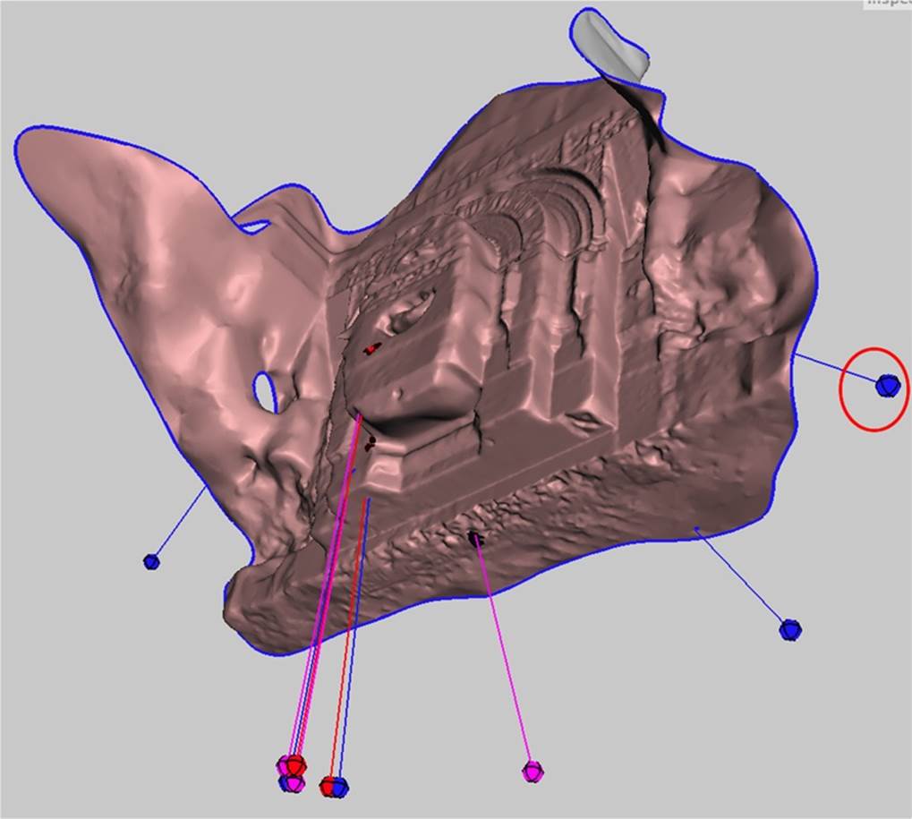
Figure 6-26. Model shown with sphere indicating large area of open mesh
Repair the problem areas
Clicking on a sphere will repair the problem. Right-clicking on the sphere will select the area and allow you to edit the selected part of the mesh. When you right-click, editing options will appear on the side of the screen.
First, left-click on any red or magenta spheres to close the nonmanifold areas and reconnect the components. The sphere and indicator line will disappear after you click on it, indicating that the problem is resolved.
Next, close all of the holes by clicking on the blue spheres, with the exception of the sphere that represents the large area of missing/open mesh. Orbit around the model to make sure you get them all.
Select the last sphere
Next, right-click on the last blue sphere that represents the large area of open mesh (see Figure 6-27). The blue edges will now have a dark orange tint to them where the mesh is selected, as shown in Figure 6-28.
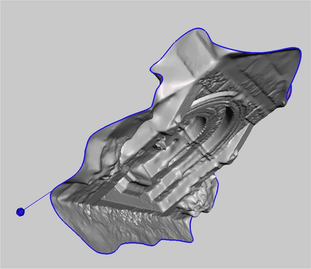
Figure 6-27. One sphere left—time to cap the hole
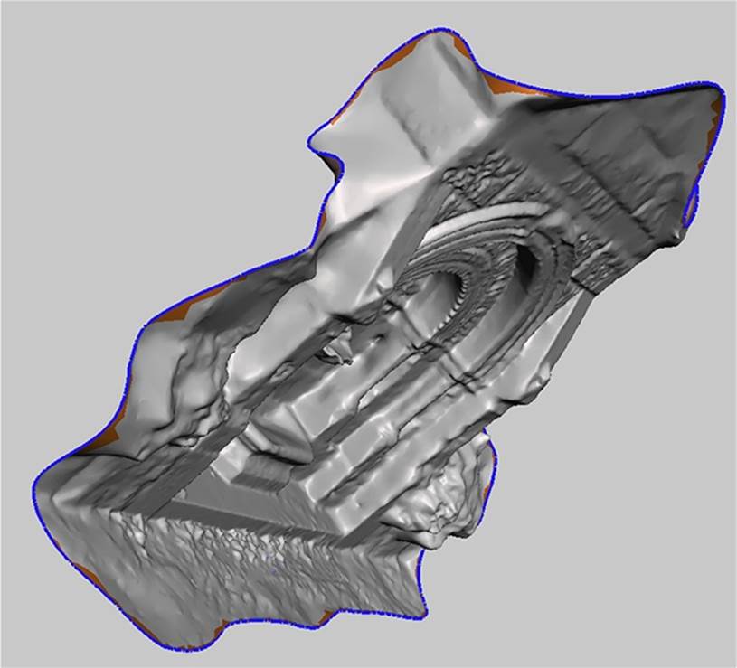
Figure 6-28. Selected edges
Smooth out the edges
From the menu at the top of the screen, select Analysis and then Smooth Boundary, as shown in Figure 6-29.
Then click Accept from the top menu. Figure 6-30 shows the result.
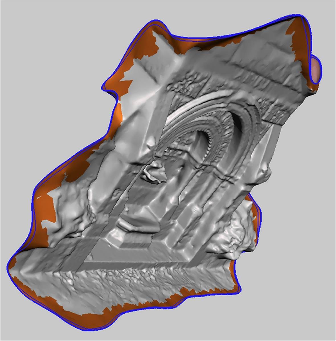
Figure 6-29. Smoothed edges
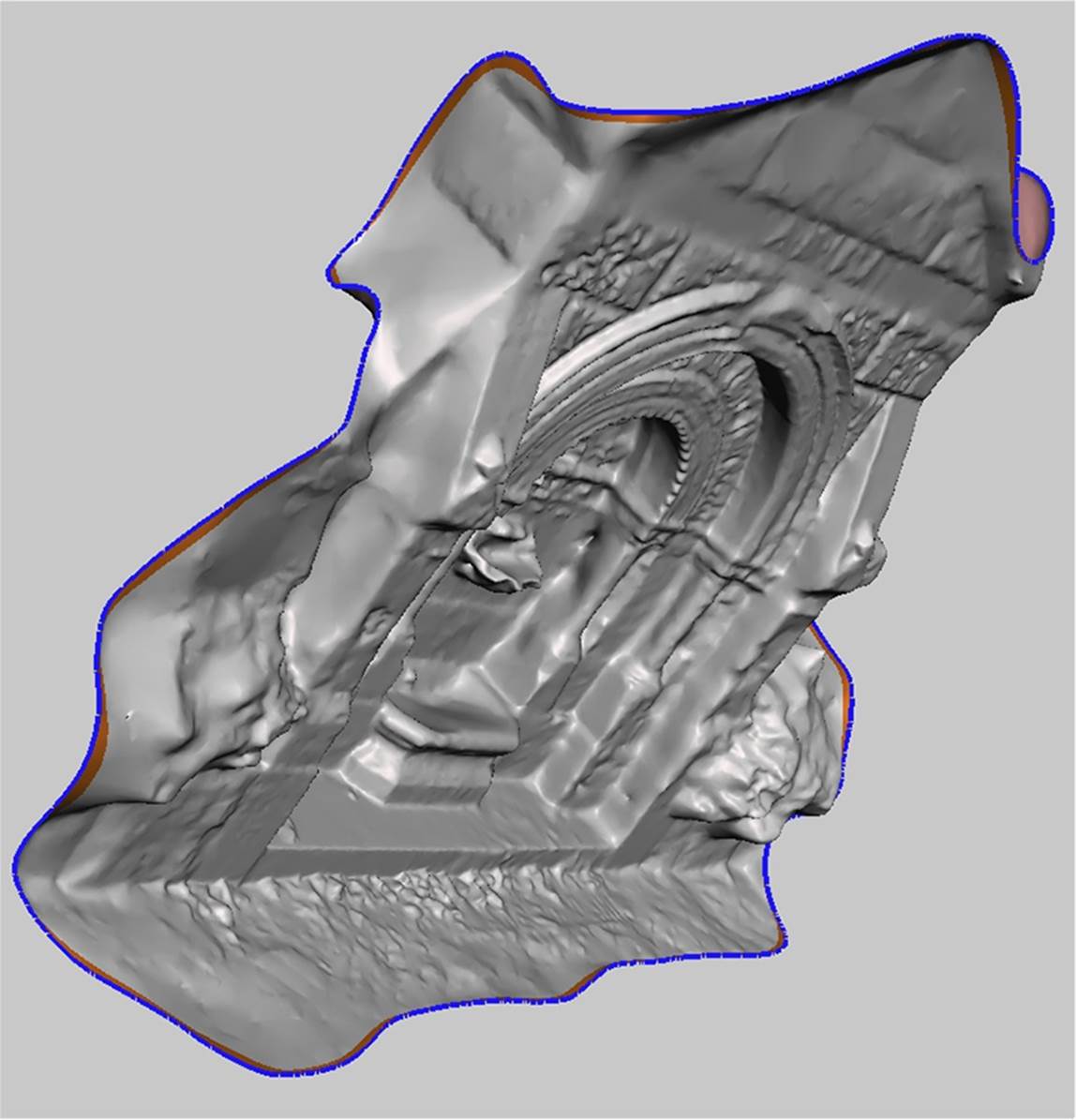
Figure 6-30. Done smoothing
Closing Large Areas of Missing Mesh
First repair the model and smooth the boundary, as outlined previously. Then:
Rotate the model (if necessary)
For this example, the model needed to be rotated so that the sides could be extruded (see Figure 6-31). You may need to rotate your model to get a better view of the missing mesh area.
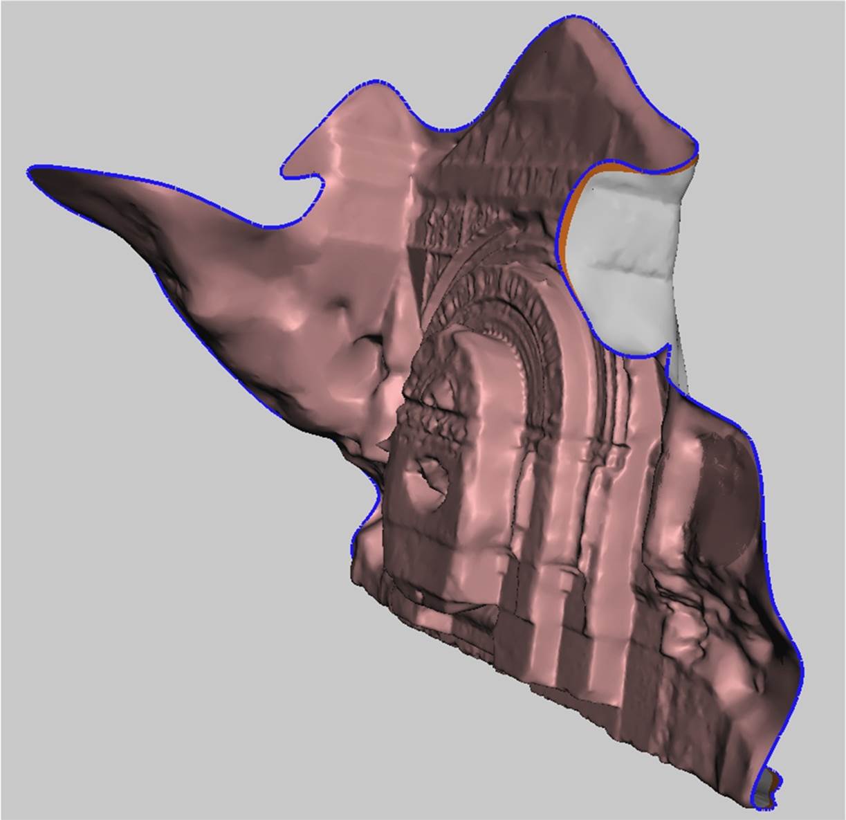
Figure 6-31. Rotated model
Select Extrude
With the boundary still selected, click the Select menu → “Edit” → “Extrude”.
Mesh selections in MeshMixer will stay selected until you manually click Clear Selection/in the Select menu, or press Esc.
Extrude the model
From the extrusion options panel, choose Flat from the EndType drop-down menu.
Under Offset, choose an offset number that is negative. You can drag the grey bar behind the Offset label to the left or right to change the offset extrusion.
You may also need to change the Direction option to get a straight extrusion. In this example, the direction was changed to “Y Axis.”
When you are satisfied, click Accept the top navigation bar. Our model now looks like Figure 6-32.
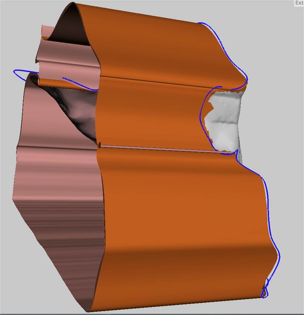
Figure 6-32. Extruded sides
Smooth, then rotate
From the top navigation bar, click on Modify Selection menu and select Smooth Boundary.
Then click Accept.
Rotate your model so that you are looking head on at the open area. (See Figure 6-33.)
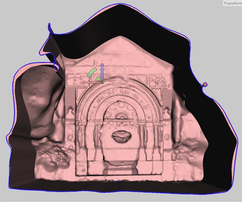
Figure 6-33. Rotated model
Sometimes MeshMixer will crash at this stage. It will usually allow you to open the model again. Save often in the default MeshMixer .mix format to ensure that none of your changes are lost.
Transform faces
From the Deform menu, select Transform Faces.
Arrows in the x,y,z plane will appear. Scale the extrusion in by dragging on the white box between the arrows. Do not close the hole completely. Figure 6-34 shows this.
Then click Accept.
Erase and fill
Now we need to close the hole. From the Edit menu (under Select), select Erase & Fill.
Then click Accept. The result is shown in Figure 6-35.
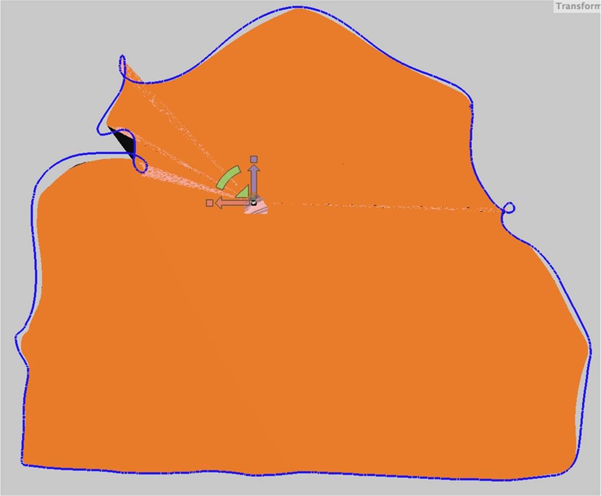
Figure 6-34. Closing faces
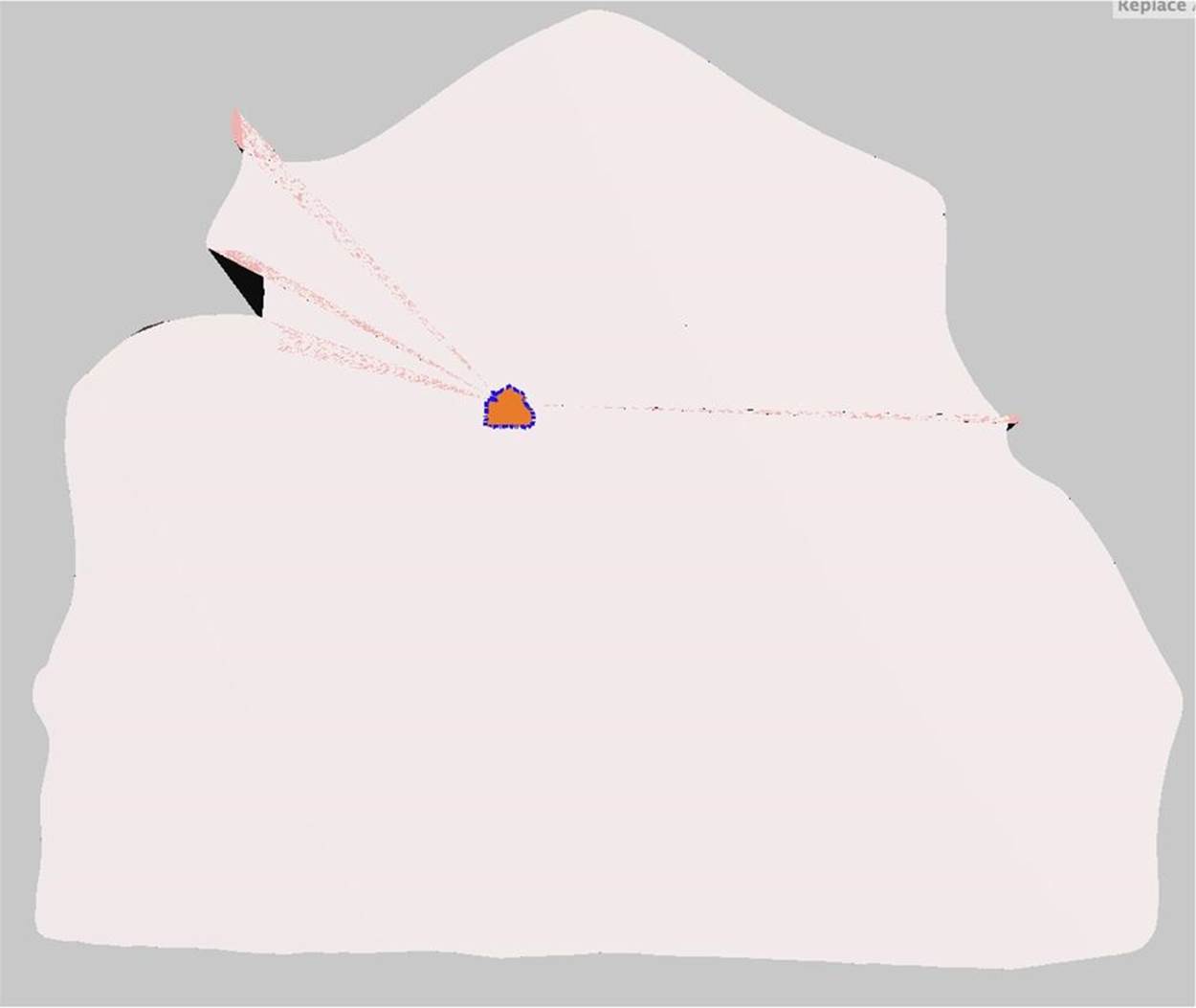
Figure 6-35. Erasing and filling
The model should be manifold and appear “capped” with a flat back.
Deselect
This model has some ridges in the roofline resulting from the extrusion that need to be smoothed out and repaired.
Click on the Select menu in the navigation bar and click Clear Selection, to clear the previous selection. See Figure 6-36.
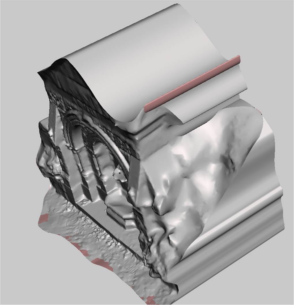
Figure 6-36. Preparing to reduce a ridge
Smooth with the Flatten and Reduce Brushes
These ridges will not smooth out with the Smooth brush, so we need to use additional brush tools.
Select and use the Flatten and Reduce brushes (Figure 6-37) to flatten out the bumps.
Then use the brush to soften it out. Figure 6-38 shows the results.
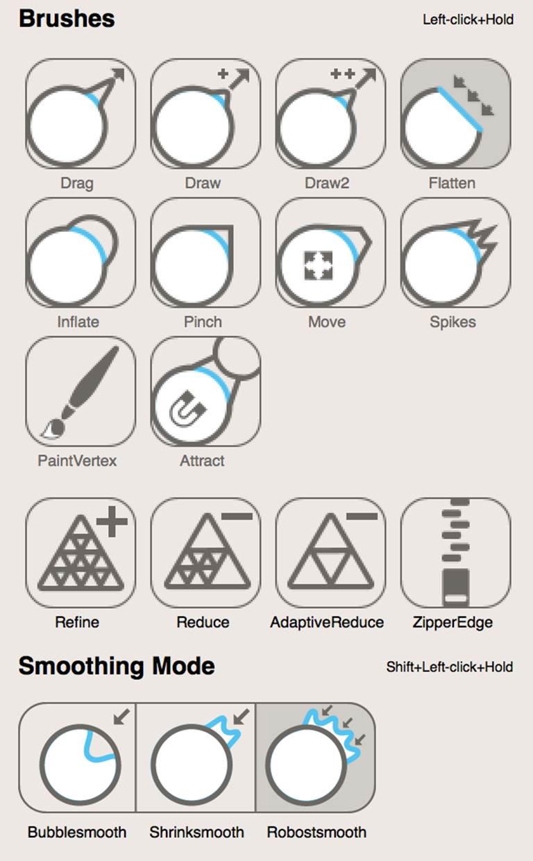
Figure 6-37. MeshMixer Brushes
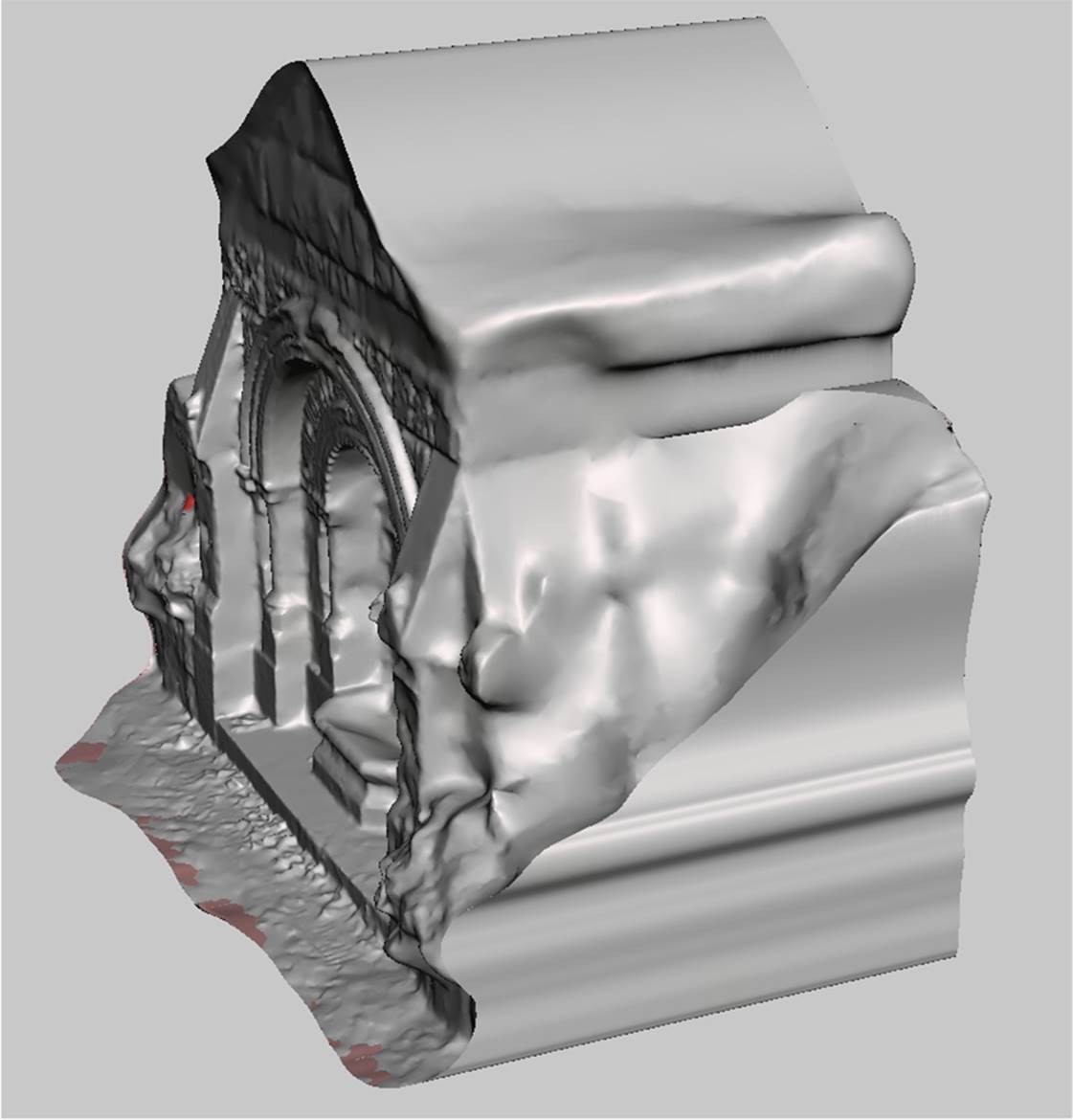
Figure 6-38. Reduce brush results
Export your file as an STL and then open it up in NetFabb. See Figure 6-39.
Slice and repair in netfabb
Use the same process detailed in Repair and Clean Up in netfabb to slice off unwanted parts of the model, repair the mesh, and then export it as a binary STL. Your model should now be capped, cropped, and ready for printing (Figure 6-40)!
Figure 6-41 shows a photo of the final printed model.
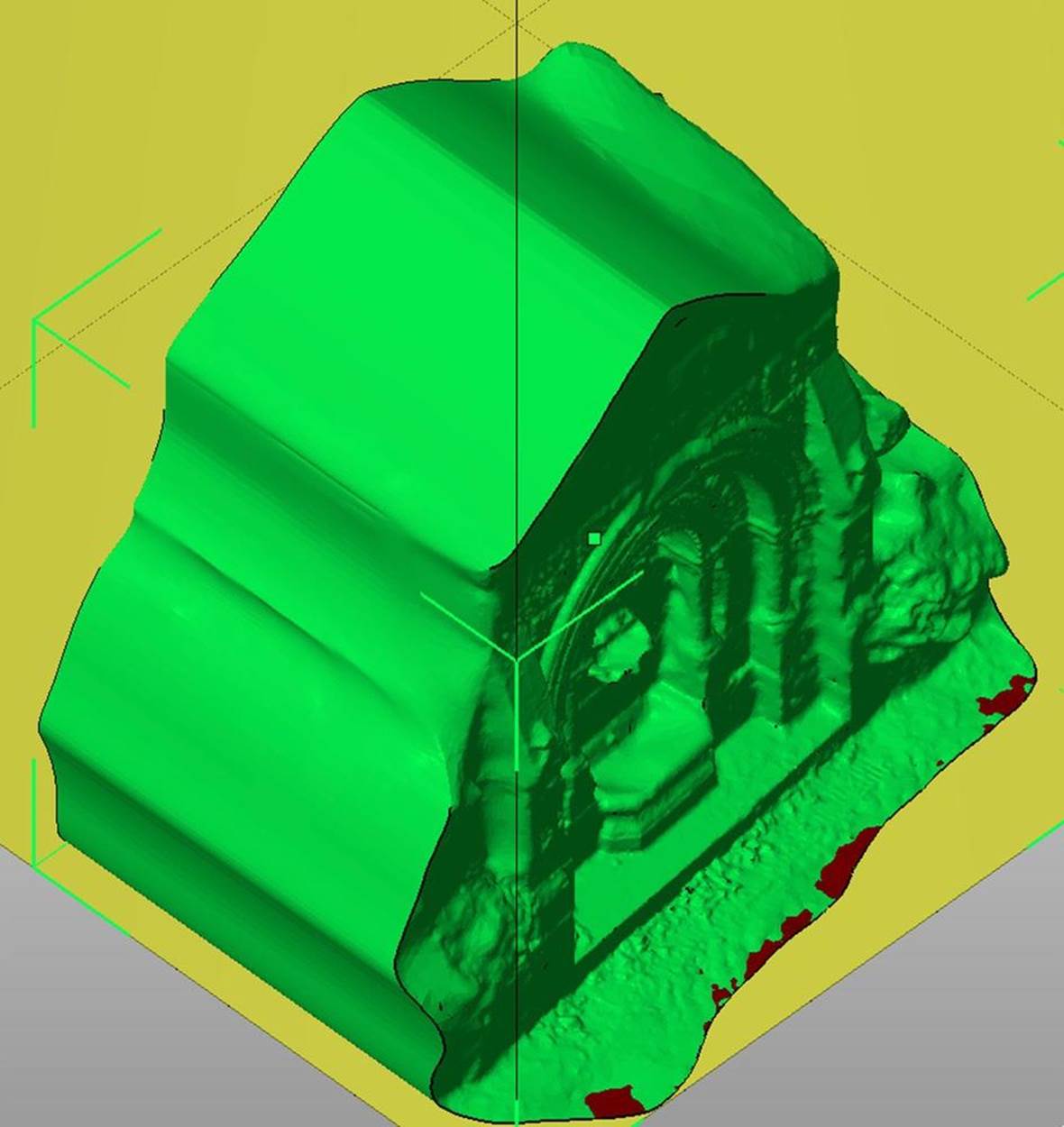
Figure 6-39. The model in netfabb
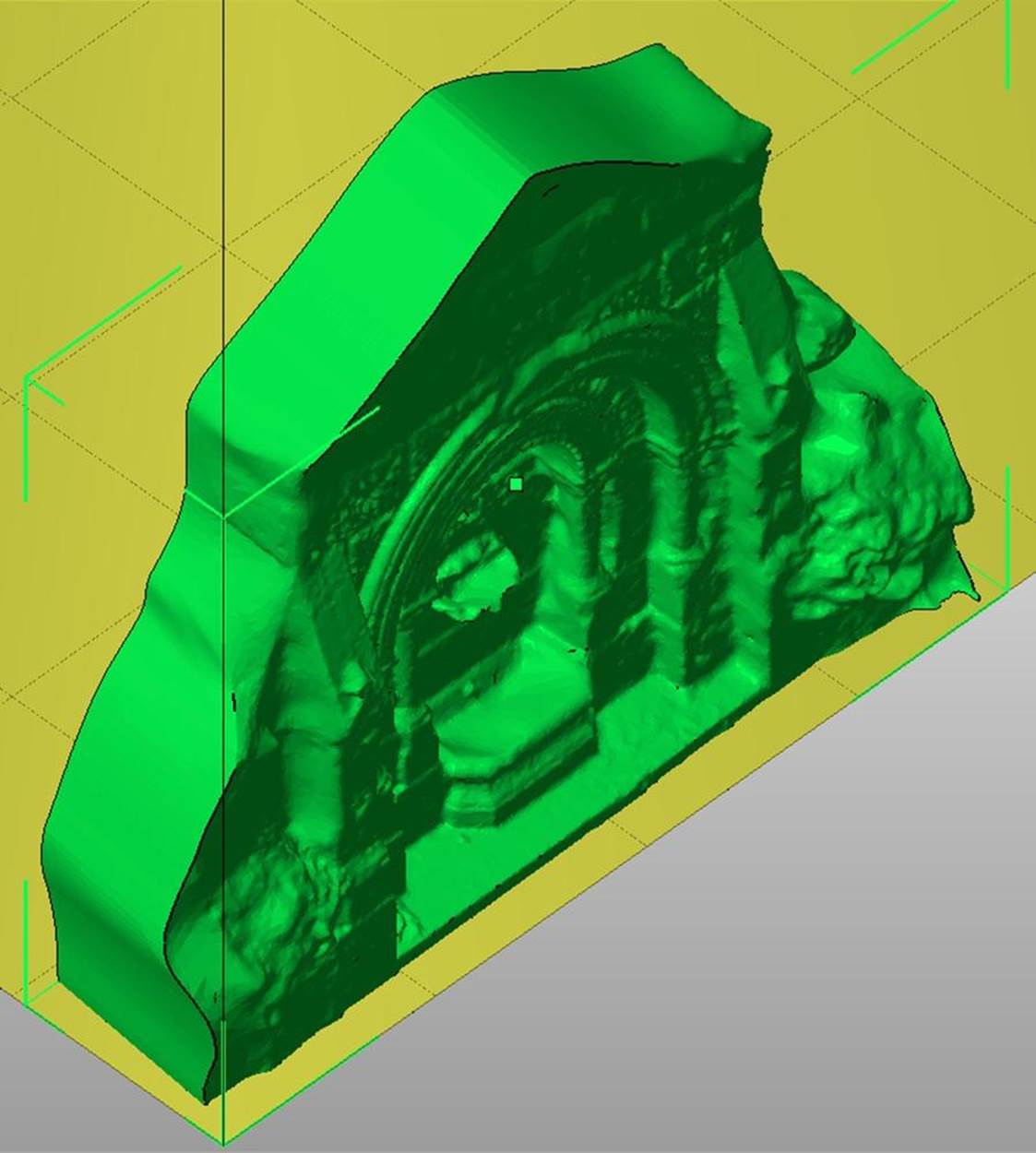
Figure 6-40. Model ready to print
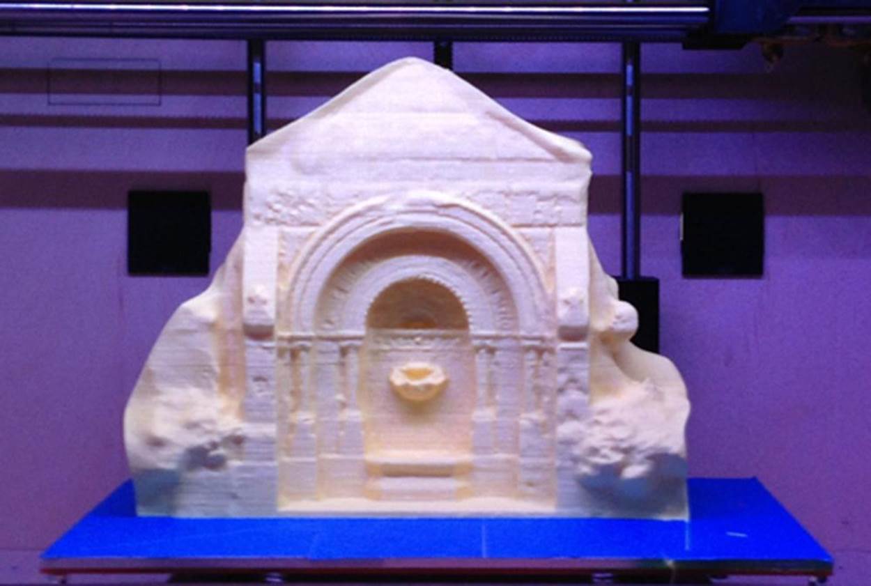
Figure 6-41. Printed scan of the gothic fountain outside the Providence Athenaeum
Scan Your World
With the tools and techniques outlined in this chapter, you’re ready to scan anything that you can convince to sit still for a while. And even if you end up with messy meshes, you can clean your can up well enough that you should be able to print almost anything you can scan. It’s time to digitize the world around you.
The scans and models from this chapter are available on Thingiverse and 123D Gallery.
Anna Kaziunas France is the Digital Fabrication Editor of Maker Media. She’s also the Dean of Students for the Global Fab Academy program and the co-author of Getting Started with MakerBot. Formerly, she taught the “How to Make Almost Anything” rapid prototyping course in digital fabrication at the Providence Fab Academy. Learn more about her at her website and check out her things at her Thingverse page.