3D Printing with SketchUp (2014)
Chapter 4. Understanding Model Resolution
In this chapter, we will learn about wall thickness and some different methods to create the wall thickness you want. We will explore circles, arcs, and how changing the number of segments they are made of affects the appearance of the printed model. We'll learn how to overcome the dreaded missing faces problem, which happens frequently when faces are not created at the time of modeling at a small scale in SketchUp.
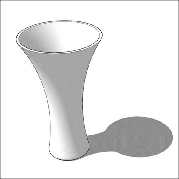
So, first a bit of high-level theory, and then we'll get to the fun part—modeling the vase in the following figure:
Wall thickness
Wall thickness is a very important concept in 3D printing. Although physics plays no role when designing on your computer, once the design makes it out into the real world, it must abide by the laws of nature.
Because it is so easy to zoom up into any detail of your model and make it fill your screen, a very common problem new designers face is understanding the model's scale in the real world. When holding your very first print, you'll likely be surprised at its size, usually by how small it is. For this reason, even though a design may look just fine on your screen, it can break in real life if its wall thickness isn't strong enough to support it.
At the same time, you don't want your walls to be too thick, or you'll use more material than necessary, costing you more money. Wall thickness is a balance that you as a designer will optimize for each model.
Wire thickness measures the diameter of a cylinder, and typically needs to be slightly larger than the minimum wall thickness. Some examples of wires are tree branches, truss struts, and the arm of a superhero figurine. A tree branch connected at one end would be considered a free wire, while a truss strut connected on both ends is a supported wire.
Detail size is related to wall thickness. For example, if you're printing a scale model of a house, the wall thickness would be the thickness of the structural walls, while the detail size would be how far the window trim sticks out from the wall. In general, detail size is smaller than wall thickness.
Wall thickness and other related requirements depend on the printing process, and vary according to the material choice and printer resolution. If you're using a print service, look for technical specifications on their website. If you own a desktop printer, print resolution will depend on the nozzle size and layer resolution supported by that printer. These specifications will be available on the manufacturers' website.
As an example, the following screenshot shows a partial list of design guidelines for minimum walls, wires, and details in Strong & Flexible Plastics available at www.shapeways.com:
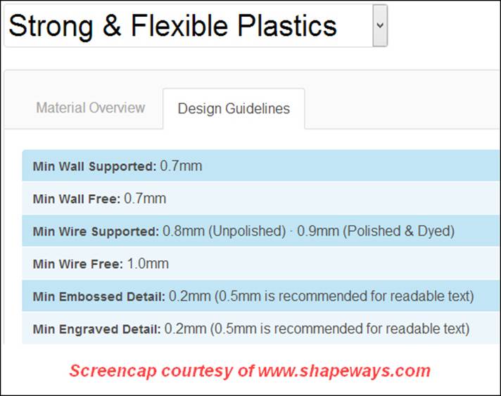
As you can see, these are the minimum requirements—you should not design any feature smaller than those indicated, and usually should design most features somewhat larger.
Now let's model!
Modeling a vase
Modeling a vase can be a simple, rewarding exercise to help us understand wall thickness, model resolution (versus layer resolution), and build on our knowledge of overhangs. Adding handles will demonstrate how to use the Outer Shell command to combine several solids into a single manifold shell. Follow along in SketchUp as I walk through the steps and thought process I used when creating this vase.
Creating a profile
While there are several ways to model a vase, the easiest is using the Follow Me tool. The first step is to create the profile of one half of the vase, as shown in the following figure:
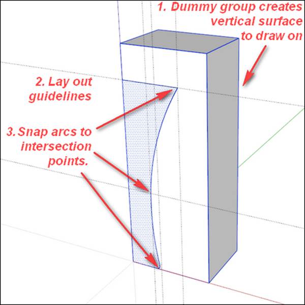
Let's break this figure down. The first thing I did was create a temporary rectangular box larger than the vase profile and make it into a group. I did this so that I had a vertical surface to draw on, making certain the profile is perfectly aligned with the red and blue axes. The box is grouped so the new geometry doesn't stick to it, and I can also use the edges of the box to assist in drawing the vertical and horizontal guidelines in the next step.
The second step was to draw horizontal guidelines (using the Tape Measure tool) corresponding to the top edge and the waist of the vase. Then I drew the vertical lines corresponding to the top edge, the base, and the waist. The intersections of these guidelines create points that allow me to accurately place arcs in the next step. The exact size isn't as important at this point as the proportions of the profile but, to give you an idea, the dummy box is 150 mm tall.
Using the Arc tool, I connected the intersections for the top, center, and bottom of the vase. Then I used the Line tool to draw the top edge, the vertical center line, and the bottom edge of the vase, connecting with the arcs to create the face highlighted in blue in the previous figure.
A face will be created if all connecting edges form an unbroken loop and are on a single plane. This is why the dummy box is so useful—it is much easier to draw on another face than in midair.
Avoiding missing faces by scaling up your model
Often when performing a Follow Me operation on a small model, SketchUp fails to form some or all of the tiny faces. The way to prevent this is to scale your model bigger by an easy-to-remember number such as 100, and then perform the operation.
While it is possible to scale the entire model or a portion of the model with the Scale tool, I find it easy to forget what scale I'm working at, so I use a simple trick to help me remember. Notice the 50 mm line in the following figure:
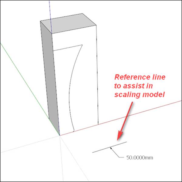
This is a reference line I drew near the origin of the model. Then, I get the Text tool by navigating to Tools | Text (not the 3D Text tool) and click on the center of the line. By default the Text tool creates a label with the length of the line, helping me remember how long it is supposed to be. The length doesn't matter, just so long as it's an even number and long enough to see easily.
To scale up the model, use the Tape Measure tool and click on one end of the line first and then the other. Type in a new measurement, say 5000 mm, and hit Enter. SketchUp will ask if you want to resize the model; click on Yes.
Now you can perform your operations without any missing faces. When your model is complete, resize the model using the Tape Measure tool again, but this time typing in 50 mm, the measurement you created earlier with the Text tool.
Creating wall thickness
For our vase example, we'll create a wall thickness of 2 mm. After saving the original vase profile, make two copies of the profile along the red axis. We are making these copies as backups because we can't access the previous state of the model without using theUndo command. As we discussed in Chapter 3, From 2D Drawing to 3D Model, making a copy in the SketchUp file before you perform important actions creates a historical timeline that you can access in case you want to branch off and try something different.
Select all of the bottom and side arcs; then with the Offset tool, offset the lines inward by 2 mm. This creates the wall thickness that we need. Clean up all the extra edges, leaving only the nice, even 2 mm-wide profile shown on the right side of the following figure:
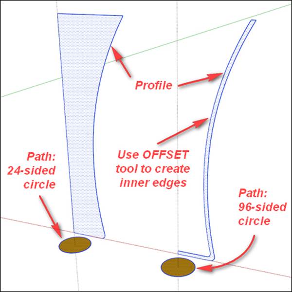
Cleaning up all extra edges is an important step. Zoom up close to see that you erase the tiny ones, too, because even these will cause your model to not become solid.
Notice the vertical guidelines passing through the center line of each profile. Create and use these guidelines to form a circle that you'll use as a path for the Follow Me tool in the next step. The guidelines will pass through each circle's center.
Understanding noncircular circles
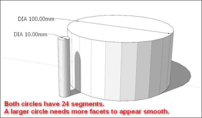
To help understand the next step, let's take a short break from modeling for some theory. Circles and arcs in SketchUp are made from a number of line segments. You can see this for yourself if you draw a circle and zoom up close to it. By default, there are 24 segments in a circle and 12 segments in an arc. This is important when talking about the resolution of your model.
You can see that, if you draw a circle with radius 50 mm, each of the 24 segments comprising the circle will be about 13 mm long. If you made the circle with a 5 mm radius, the segments would be 1.3 mm long. If you then extrude the two circles into cylinders, the segments form the facets on the cylinder. The 13 mm facets on the large cylinder will be very noticeable, but the 1.3 mm facets on the small cylinder will not show nearly as much, as shown in the following figure:
You can easily change the number of segments in circles and arcs in SketchUp before they are extruded (for more details on changing circle segments refer to a help article at http://help.sketchup.com/en/article/94740). Since you cannot change the resolution afterextruding, you'll want to think about the resolution at the start.
The length of line segments on your curves forms what I refer to as model resolution. Model resolution affects the appearance of your printed model. If you want a smoother looking model, increase the segment count of curves. In general, if your segments are 1 mm or smaller, you won't notice them on the printed model; however, for high resolution printers, you may want to decrease the resolution to 0.1 mm or even smaller. This is because a higher resolution printer will show facets more clearly and therefore will require a model with more segments in the curves to look smooth.
Making the magic happen with the Follow Me tool
Now for the fun part! Select the circle path first, and then click on the corresponding profile with the Follow Me tool. Repeat for the other profile to make two vases as shown in the following figure:
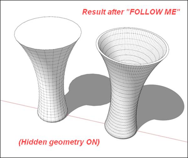
You probably noticed that the circular paths in the figure we saw in the previous section are labeled differently, although from a distance they look the same. The one on the left has 24 segments by default, while I set 96 segments for the one to the right.
Notice how the resulting model on the right has many more segments. With its much higher model resolution, it will look and feel much smoother after 3D printing. Higher segment counts also make more dimensionally accurate curves.
A smart reader will infer that we can also increase the segments of the profile curves in addition to the path curves, and you would be completely correct! You can completely control the resolution of any curves in your model, as long as you adjust them before extruding.
In some cases, you may not want a smoother print for artistic or other reasons. In this case, it is perfectly acceptable to use a lower path resolution.
In the following figure, we can observe that each vase used the exact same profile, but the number of path segments is denoted by the numeral below each vase. Each vase is printable and looks unique from the others:
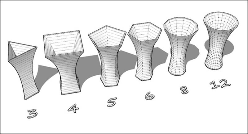
As with wall thickness, the number of segments you use in an arc should be balanced. Too many and you'll increase file size, increase processing time, and have trouble with missing tiny faces; too few and your model will look faceted and unpolished.
A bonus tip for desktop extrusion printers
Notice how I created one vase with 2 mm wall thickness, while the other vase is solid. The solid vase actually prints better on desktop extrusion printers because you can tell the printer to make a certain number of passes around the perimeter, and not fill the center. Keep reading for a photo of the final vase printed using this method!
Combining solids with the Outer Shell tool
When adding major features to your model, I find it useful to keep the parts separate until the end of the modeling process, and then combine them into the final solid printable model. This approach makes it easier to edit the different parts of the model if you ever want to go back and change something.
For example, let's say we want to add handles to our vase. First, make a copy of the vase along the red axis, and make it into a group. Be sure the group is solid before continuing.
In the following figure, I have a dummy group running through the center of the vase. This creates a surface to draw the path for the handle, as shown:
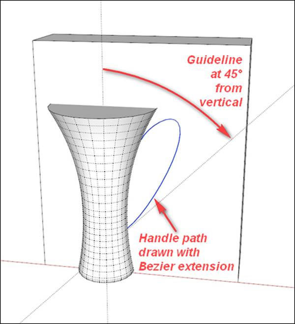
To draw the path for the handle, I used the BezierSpline extension by fredo6 http://sketchucation.com/forums/viewtopic.php?t=13563. This extension allows you more freedom than the Arc tool when creating curves.
In the previous chapter, we discussed the 45-degree overhang rule for desktop extrusion printers. Since I wanted to print this vase at home, I created a guideline at 45 degrees from the vertical. As long as the handle does not exceed the angle defined by the guide, I know it should print fine.
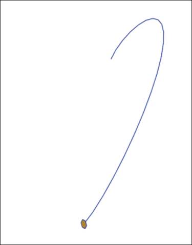
The next step is to draw the profile for the handle. I used a circle with radius 2 mm and 6 sides (shown at the bottom of the path in the following figure). I deleted the dummy group and used the Hide command (right-click on the object and click on Hide, or go to Edit| Hide) on the vase to temporarily isolate the profile and path:
Perform the Follow Me operation, and make the resulting handle into a group. Unhide the vase (by going to Edit | Unhide | Last). Move the handle slightly so that its ends are completely inside the vase group, as shown in the next figure:
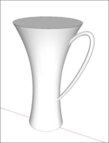
Make a copy of the handle on the opposite side of the vase. Right-click on the handle and go to Flip Along | Group's Red, to make a mirror image of the handle. Once again, move it into place so that the ends are completely inside the vase group.
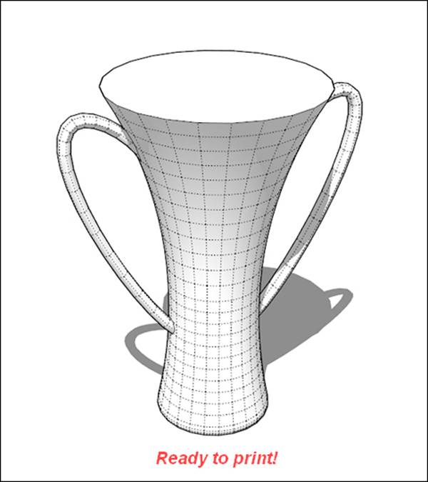
You should now have three solid groups—the vase and two handles. Make a copy of all three along the red axis, helping create that history of important steps in your model. All that remains is to combine them using the Outer Shell command into a single solid object, as shown in the following figure. Export it as an .STL file, and you're ready to print!
The following figure shows the final vase printed on my desktop extrusion printer. The settings I used are 50 percent scale, 0.3 mm layer height, 1 shell (perimeter), 0 percent infill, and no top layer:
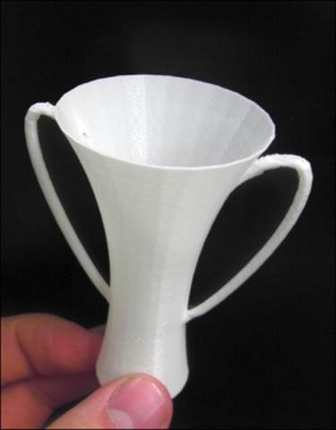
The print was a success on the very first try! Designing the handles to meet the 45-degree-overhang rule worked as intended. The printer was able to bridge the short distance connecting the top of the handle when it reached that point. The bridge could have been even smoother if I had slowed down the printer to allow cooling time for the layers below.
Notice the faceting visible on the inside of the vase. By now you know this could have been avoided by increasing the number of segments in the path. On a higher resolution printer the faceting would be even more noticeable; however, on an extrusion printer, the effect is somewhat muted because the bead of plastic slightly bends as it travels around sharp corners.
Bonus – more methods to create wall thickness
Perhaps the easiest way to create an even wall thickness is using the offset method you learned earlier in this chapter. But that method will not work in all cases. In this section, we'll discuss some more methods for creating thickness.
For symmetric shapes, you can copy/paste the shape in place, and use the Scale tool to make a smaller version of that part. Scaling from the center or selectively using the various grips, you can manipulate the copied shape to form a wall at a specified distance.
As a simple example, think of a cube—make it a group to keep the geometry from sticking to the copy, copy/paste in place, scale to something less than 100 percent, and you have an interior set of walls. You'll need to explode the groups, reverse the copy's faces, and connect the walls to the original geometry, and you'll have an even wall thickness.
JointPushPull Interactive is a plugin that will also help in creating wall thickness. Authored by fredo6, this plugin is available from SketchUcation at http://sketchucation.com/forums/viewtopic.php?p=496773. For more information about how to use this plugin to create thickness on complex geometry, please refer to Chapter 7, Importing Terrain and Printing in Color.
Summary
In this chapter, you learned about wall thickness and several methods of creating thickness. Balancing wall thickness to create enough strength without wasting material is a skill you'll learn with practice.
We discussed how adding segments to your curves improves model resolution, and how to balance model resolution with the accuracy of your printer. More curve segments = smoother model = bigger file size. Too large a file size makes SketchUp run slower.
You learned that SketchUp doesn't work well with tiny faces, and an easy trick to scale your model up and back down quickly and accurately. Finally, you saw how keeping major features of your model as separate solids allows for ease of editing until the end of the modeling process. Later, you can use the Outer Shell command to combine multiple solids into one for printing.
In the next chapter, we'll learn how to save and reuse models we create. We also discover websites to download 3D models that other designers have made freely available, and how to edit and adapt a model to fit our needs perfectly.