3D Printing with SketchUp (2014)
Chapter 6. Designing a Phone Cradle
Do you know that feeling when you're watching a video on your smartphone or tablet, and you'd like to place it down, but then it's hard to view, so you end up holding it anyway? Or you're video chatting and need both hands to show how something works, but you can't do so. These are prime examples when a phone cradle can come in handy.
In this chapter, we'll design a cartoon jet phone cradle. This one will be a hit with the kids and a great learning experience for anyone learning how to design for 3D printing.
We will learn about saving time by designing half of a model and then mirroring the remaining part to finish quickly. We will discuss iterating the design, printing text in the model, and how to use the Intersect with Model command.
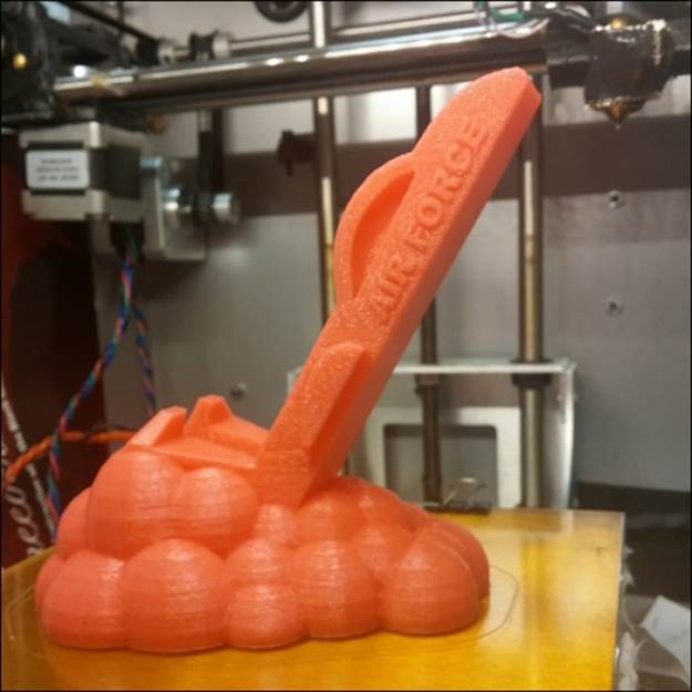
The following is a photo of the completed cradle:
Getting started with a 2D sketch
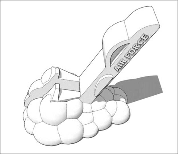
The vision for this model is a jet taking off at a steep angle, leaving behind clouds of smoke and dust. The clouds will provide a wide base to support the phone in either the portrait or landscape mode.
This model is to be printed on an FFF desktop printer, so we should keep in mind the 45-degree rule and think about minimizing support structures. We can also keep the geometry at a lower resolution to match the capabilities of the printer.
We're going to start by creating a dummy box and drawing on one of its vertical sides, just like we did in Chapter 4, Understanding Model Resolution. The following figure shows the profile outlines drawn using the Line and Arc tools:
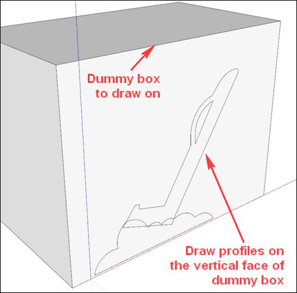
The preceding figure does not show the temporary 45 degree SketchUp guides used to ensure that the overhangs are not too steep. For more details on this technique, refer to Chapter 4, Understanding Model Resolution. The cloud and jet profiles are drawn as separate groups and will be joined after pulling into 3D.
Getting to the third dimension
At this point, you'll want to scale your model to size. Using the Tape Measure tool, scale the model to size it to 100 mm in height.
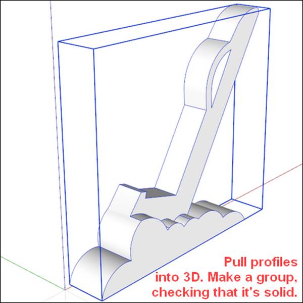
In the following figure, we pull the profiles into 3D, making the cloud base 18 mm thick and the jet 12 mm thick. We join the two groups with the Outer Shell tool, ensuring the result is Solid:
Adding details to make the model interesting
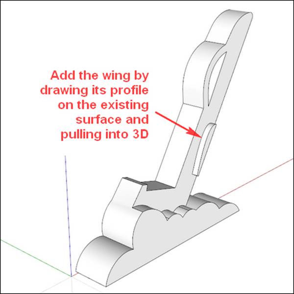
In the following figure, we open the group and draw a wing profile on the existing face of the jet. As the wing is not a true arc, the Bezier Curve Tool extension works best for drawing the curved portion. To minimize the support needed, we'll just pull the wing out by 1.5 mm:
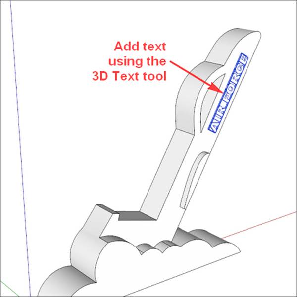
Using the 3D Text tool
Next, we'll add some text with the 3D Text tool. I wrote AIR FORCE, but you can write anything, even your name if you like!
Tip
For 3D printing, non-Serif fonts such as Arial work the best, and bold versions print even better. This is because at small sizes, the thinnest parts of Serif fonts are too thin to be shown in the final print.
In the Place 3D Text dialog box, the height should be 5 mm. Make sure the Extruded box is checked, and set the thickness to about 0.6 mm. For best results, place the text close to where you want it to go, and then use the Move and Rotate tools to place it precisely. You'll want to keep the text as a separate group for now.
The 3D text will automatically orient itself to align with whatever face you place it on, and then is glued to that plane when you let go of the mouse button. If you're ever trying to move the 3D text and it isn't cooperating, right-click on the text and click on Unglue; the text will come free from the original plane.
In the following figure, the 3D text is aligned with the jet and placed near its nose:
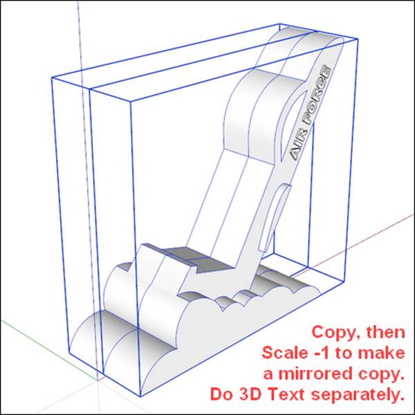
Mirroring symmetrical models
In symmetrical models such as this one, it is good practice to create half of the model and then mirror the geometry to quickly finish the model. This practice is a huge time saver that we can use now.
In the following figure, we copy the model, scale the copy with a -1 factor using the Green Scale about Opposite Point grip, and move it adjacent to the first model, creating a mirrored version of the model and doubling our efforts very quickly. The 3D text must be copied and realigned separately—mirrored text is difficult to read! Another option to mirror the model is to right-click on it and navigate to Flip Along | Group's Green, where Green refers to the green axis:
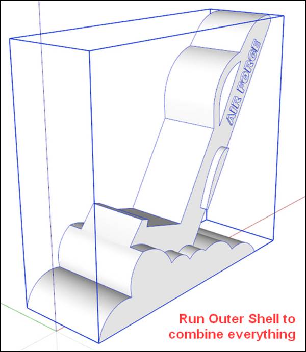
Combining groups with the Outer Shell tool
In the following figure, we copy all the groups to create a historical timeline. Then, we select the 3D text and mirrored groups and use the Outer Shell tool to combine everything into one solid model:
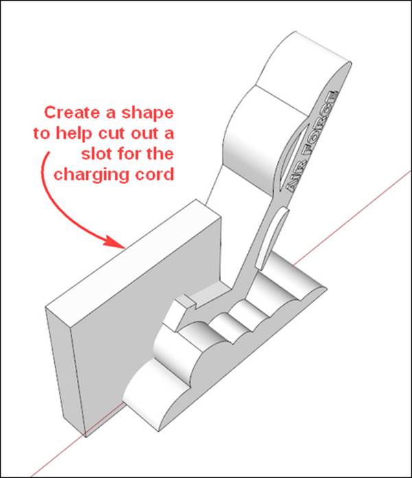
Cutting a slot for the cord
If we think about the final details of the model, we may want to use the cradle with the phone in the portrait mode while charging. On many phones, the charger connects at the bottom of the phone, so we'll need to account for that.
Cutting in a slot will allow us to accommodate the charger and take the phone off the cradle, without unplugging the cord. There are two ways to create a slot through this complex geometry: with the Solid tools (Pro version only) or with the Intersect with Modelcommand (Make or Pro versions). For now, we'll discuss the Intersect with Model command. The process is nearly the same for Solid tools but without the tedious cleanup.
We start by creating a box whose width is 13 mm, centered on the group. I chose a width of 13 mm after measuring my phone charger and adding a few millimeter units of wiggle room. The length and height are not important so long as they extend up to or beyond the parts of the model you want to cut.
In the following figure, you can see the orientation of the box that we'll use to create the slot. When complete, the box and everything inside the box will be removed:
For the Intersect with Model command to work, the parts need to be in the same context, which means the parts to be intersected must not be in separate groups. Select the entire box and go to Edit | Cut to remove the box and copy it to the clipboard. Open the cradle group and go to Edit | Paste in Place to put all geometry in the same context, keeping the placement of the box intact.
Tip
SketchUp Pro users should group the box to keep the groups separate. To cut the slot, select the box, then go to Tools | Solid Tools | Subtract, and then click on the cradle group. The box and everything it contains will be removed, leaving a clean slot.
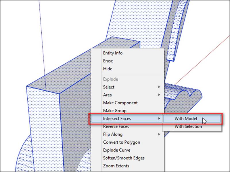
In the following figure, we select everything, then right-click on it and go to Intersect Faces | With Model. Depending on how complex your model is, this can take a few seconds or even minutes on really big models:
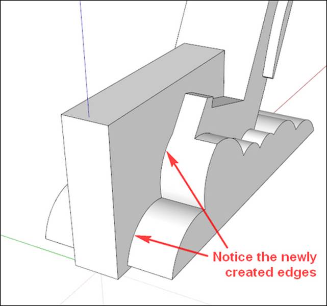
When the operation is complete, you will see that new edges have been created where the intersecting geometry meets, as shown in the next figure. Now, you can start deleting the excess geometry, taking care not to delete anything you want to keep.
This cleanup can be a tedious process—ensure that you get all the extra geometry, but do not delete anything that will make a hole in the good portion of the model. Zooming in close will help you to see tiny extra edges. The Cleanup extension can be of enormous help in this situation since it deletes any stray edges.
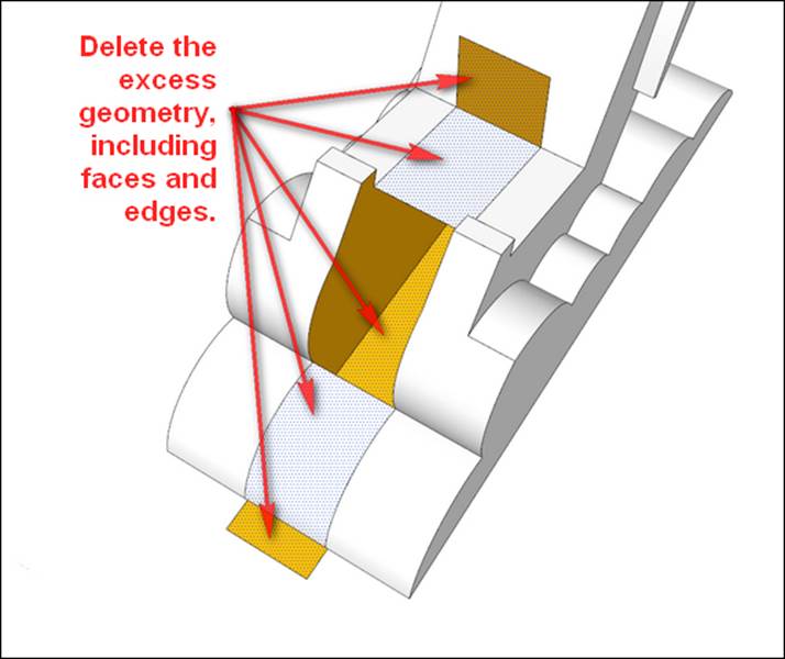
In the following figure, some of the excess geometry has been deleted. Clean up the rest and ensure that you get extra faces and edges that will prevent the model from being solid:
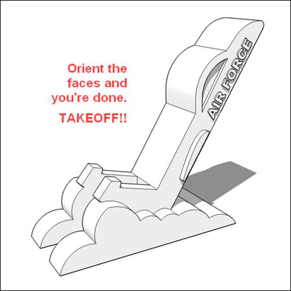
Orienting faces for a perfect model
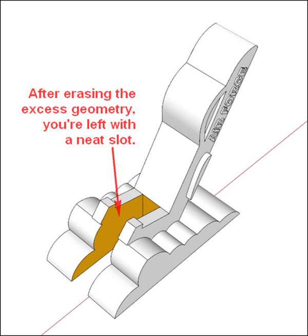
In the following figure, all the excess geometry has been deleted, which leaves behind a perfect slot. Some faces are reversed but are easily corrected by right-clicking on a white face and then on Orient Faces:
Tip
If the Orient Faces command isn't working as you expect it to, the model likely isn't a solid. Check the model for interior faces and delete them.
Exporting the model for printing
In the following figure, all faces are oriented correctly and the model is ready to be printed. Export it for printing, and you're on your way!
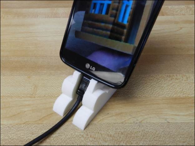
Testing the printed model
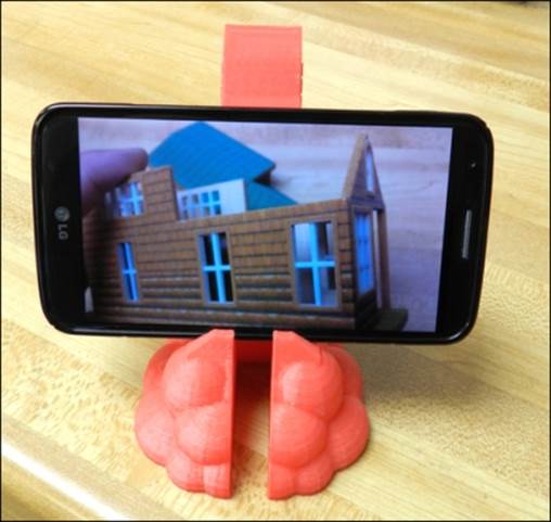
The following screenshot shows the printed cradle in use:
After printing the model and testing how it works in practice, I noted the following changes that would improve the design:
· Increasing the height and width of the tabs on the jet's tail fins to keep the phone more stable while in the landscape mode
· Increasing the height of the base so that the charger cord doesn't bend sharply on the table
· Making the jet exhaust clouds more realistic
· Making the plane wings bigger so it's easier to tell what it is
Developing an improved design
Back to SketchUp we go! We'll make the changes and print an improved model. This process of refining the design through a series of iterations is discussed in Chapter 3, From 2D Drawing to 3D Model.
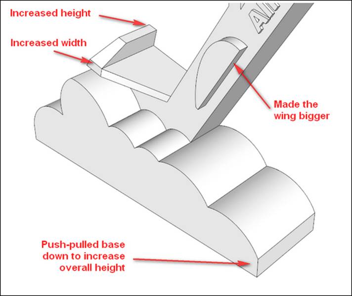
Going back in the historical timeline, copy one of the mirrored half groups to rework into the improved design. Use the Push/Pull tool and the Line tool to make the tabs that hold the phone in place taller and wider. Use the Push/Pull tool to pull the bottom face down by another 6 mm, raising the phone up so the charging cord doesn't kink.
For changing the wing shape, push the wing back flush with the plane body, and use the Bezier tool to create a new, larger wing profile. Erase the old curve, and use Push/Pull to set the new wing back out to 1.5 mm. The larger tabs and the new wing are shown in the following figure:
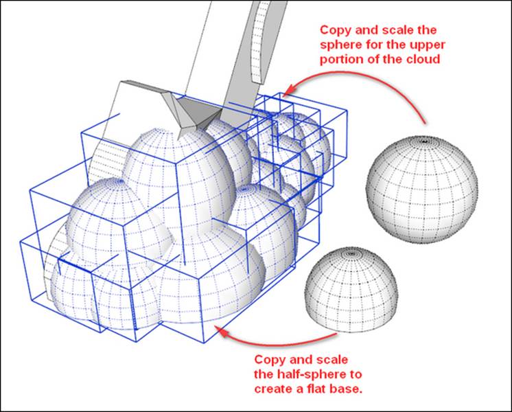
Copying and scaling groups to create a complex shape
For creating more realistic puffy smoke clouds, simply create a sphere and a half-sphere and copy them around the base. You'll want to make sure both the sphere and half-sphere are grouped and solid before making copies of them The half-sphere will create a nice flat base, and the sphere will fill in the top. Use the Scale tool to stretch, resize, and deform the copies so that it looks more realistic. Try to keep the 45 degree rule in mind so that the spheres are self-supporting as shown in the following figure. In this figure, all of the spheres and half-spheres are selected so that you can see how many of them make up the new base:
Finally, make a copy of the groups that form your new base. To prevent holes in the model when creating tiny faces in the next step, scale the model up by 100 times using the Tape Measure technique described in Chapter 3, From 2D Drawing to 3D Model. Use theOuter Shell tool to combine everything into one solid group. I found Outer Shell to work best when used on only two to three groups at a time. Selecting everything and running the tool often results in a group that s not solid.
Finishing up and printing the new model
Once you have a solid group, make a copy for the historical timeline. Mirror the group, align the 3D text, and combine everything with Outer Shell. Cut a slot using the same methods we used in the first iteration of the model. Once that is complete, you should have a model that looks like the following figure:
Export the part, and you're ready to print the updated version!
Testing the second iteration
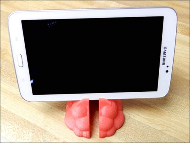
The new part worked much better, comfortably holding the phone and even a small tablet. The increased height prevents the charging cord from kinking, and the larger base looks much better, as shown in the next images. Printing with a red filament enhances the appearance as well!
In the following figure, we see that the same stand can be used for a larger device:
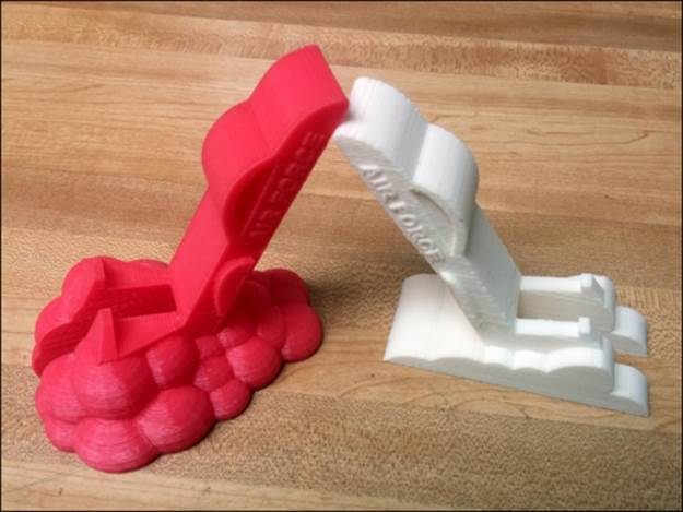
The following figure shows the difference between the two printed designs:
Summary
In this chapter, we learned some advanced modeling techniques such as the Intersect with Model command and how to use simple shapes to quickly build up a complex model. By combining these techniques, you can quickly create very complex models. We also used the historical timeline to save time while making a second iteration of the design.
In the next chapter, we'll learn about working with terrain data and how to 3D print models in full color.