Make: Basic Arduino Projects - 26 Experiments with Microcontrollers and Electronics (2014)
Chapter 9. Multicolor RGB Flasher
Free Running Switcher
In past projects, one or two LEDs, usually red and/or green, were used as visual indicators, letting us know that the Arduino had completed a task or operation. But why limit ourselves to red and green? There is a type of LED that has three different colors all in the same package. An RGB LED has three light-emitting diodes inside of it: one red, one green, and one blue.
In this chapter, you will learn how to use a multicolor LED by building a simple RGB Flasher. The parts you will use for the RGB Flasher are one fixed resistor, a multicolor LED, and an Arduino microcontroller. The RGB Flasher will be built using the handy MakerShield. The Ultimate Microcontroller Pack has all of the project parts you need. Figure 9-1 shows the RGB Flasher block diagram.
Parts List
§ Arduino microcontroller
§ MakerShield kit
§ R1: 330Ω resistor (orange, orange, brown stripes)
§ LED1: multicolor LED
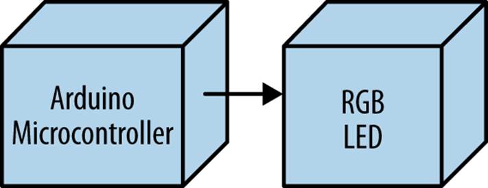
Figure 9-1. The RGB Flasher block diagram
Circuit Theory
Figure 9-2 shows a typical RGB LED with the wiring pinout names. There are three pins, one for each color, and one common pin for positive attachment to a power supply. Like the ordinary LED, the positive and negative pins are wired to the positive and negative points of a DC (direct current) circuit. To illustrate, Figure 9-3 shows three SPST (single pole, single throw) switches wired to control red, green, and blue LEDs. Closing the contacts on SPST switch SW1 will allow the battery’s (VBattery) current to flow through the red LED, turning it on. The other switches (SW2 and SW3) will turn on the green and blue LEDs as well. The individual colors can be lit sequentially or at random using the three SPST switches. The Arduino microcontroller will provide a sequential switching order, allowing the red, green, and blue LEDs to turn on accordingly.
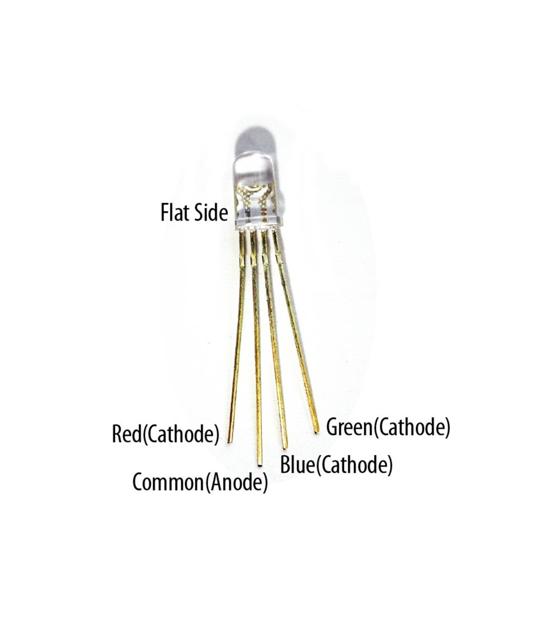
Figure 9-2. A typical RGB LED with pinout names
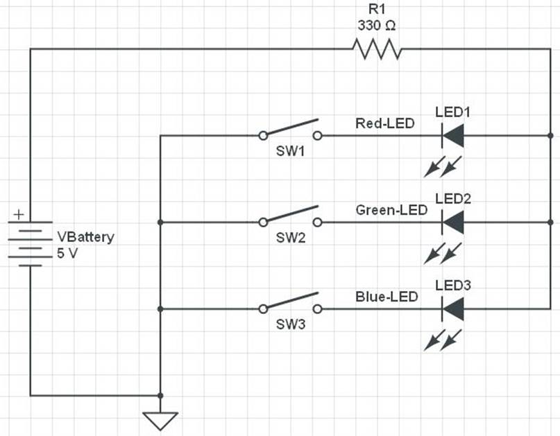
Figure 9-3. Three SPST switches controlling an RGB LED
TECH NOTE
A common anode RGB LED has all of the positive leads connected together to one lead.
The RGB Flasher
The RGB Flasher is an awesome Arduino microcontroller gadget that displays three colors (red, green, and blue) on one LED. You can easily build the circuit on the MakerShield, which will make it portable so you can carry it in your shirt pocket. You can use either the Fritzing diagram shown in Figure 9-4 or the circuit schematic diagram of Figure 9-5 to build the flasher.
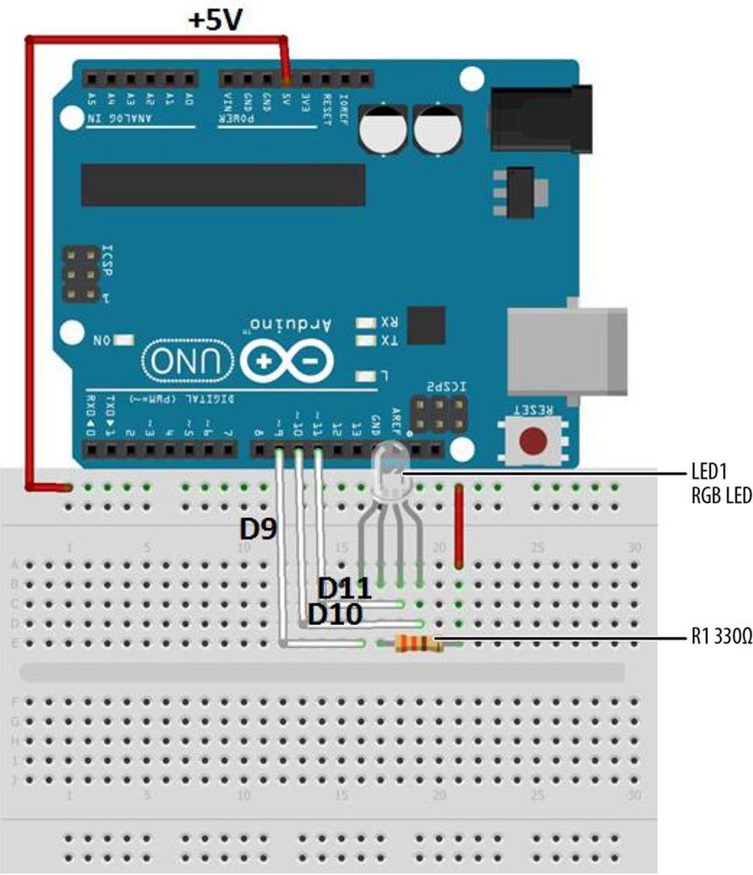
Figure 9-4. The RGB Flasher Fritzing diagram
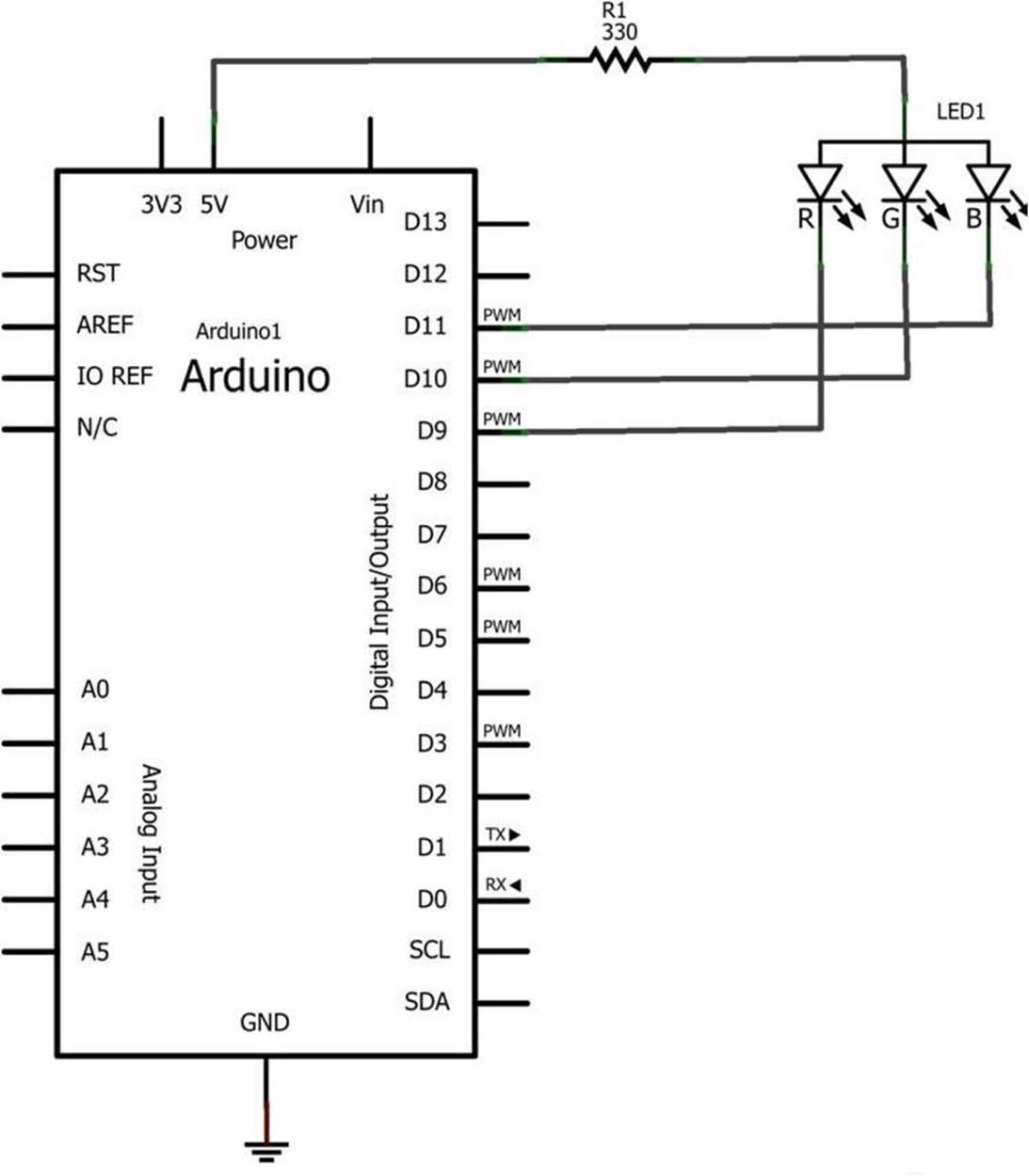
Figure 9-5. The RGB Flasher circuit schematic diagram
TECH NOTE
The common anode pin is the longest lead on the RGB LED.
After wiring the components onto the mini breadboard of the MakerShield pictured in Figure 9-6, upload Example 9-1 to the Arduino microcontroller.
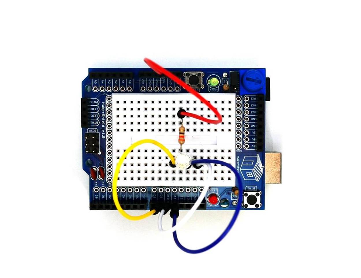
Figure 9-6. The RGB Flasher built on a MakerShield
Example 9-1. The RGB Flasher sketch
/*
RGB Flasher
Flashes the red, green, and blue LEDs of an RGB LED
Turns on an LED on for one second, then off for one second for each
color LED.
15 Feb 2013
Don Wilcher
*/
// RGB pins wired to the Arduino microcontroller.
// give them names:
int redled = 9;
int grnled = 10;
int bluled = 11;
// the setup routine runs once when you press reset:
void setup() {
// initialize the digital pins as outputs:
pinMode(redled, OUTPUT);
pinMode(grnled, OUTPUT);
pinMode(bluled, OUTPUT);
// turn RGB outputs off:
digitalWrite(redled, HIGH);
digitalWrite(grnled, HIGH);
digitalWrite(bluled, HIGH);
}
// the loop routine runs over and over again forever:
void loop() {
digitalWrite(redled, LOW); // turn the red LED on
delay(1000); // wait for a second
digitalWrite(redled, HIGH); // turn the LED off
delay(1000); // wait for a second
digitalWrite(grnled, LOW); // turn the green LED on
delay(1000); // wait for a second
digitalWrite(grnled, HIGH); // turn the green LED off
delay(1000); // wait for a second
digitalWrite(bluled, LOW); // turn the blue LED on
delay(1000); // wait for a second
digitalWrite(bluled, HIGH); // turn the blue LED off
delay(1000); // wait for a second
}
NOTE
So far in this book, you’ve been taking an LED pin HIGH to light it. This example takes a pin LOW to light it. This is because the common pin on the RGB LED goes to +5V and each element’s pin (R, G, and B) is a negative lead. As a result, each of those pins needs to be taken LOW to allow current to flow. This means that taking a pin HIGH turns it off. This is the reverse of what you’ve seen with discrete LEDs in this book where there is one positive and one negative lead. In the case of this RGB LED, there is one positive lead (the common anode) and three negative leads (cathodes).
After uploading the RGB Flasher sketch to the Arduino Microcontroller, the red, green, and blue LEDs will be individually flashing in sequence. You can change the order of the LEDs by making new sketch RGB pin assignments along with appropriate breadboard wiring changes. Like a good scientist, remember to record your observations, modified sketches, and circuit schematic diagrams in your lab notebook!
TROUBLESHOOTING TIP
If the LEDs don’t turn on in the proper sequence, check your sketch pin assignments, as well as the orientation of the component on the MakerShield mini breadboard.
Something to Think About
Are there common cathode RGB LEDs? If so, what Arduino microcontroller wiring changes are needed to operate them correctly?
All materials on the site are licensed Creative Commons Attribution-Sharealike 3.0 Unported CC BY-SA 3.0 & GNU Free Documentation License (GFDL)
If you are the copyright holder of any material contained on our site and intend to remove it, please contact our site administrator for approval.
© 2016-2026 All site design rights belong to S.Y.A.