Make: Basic Arduino Projects - 26 Experiments with Microcontrollers and Electronics (2014)
Chapter 10. The Magic Light Bulb
Pushbutton Multicolor Flasher
Here’s a cool trick you can play on a friend using the Arduino and an RGB LED. Build an RGB flasher with a mini pushbutton switch on an Arduino MakerShield. Show your friend the MakerShield and tell him the mini light bulb is magical and it can produce three colors: red, green, and blue. Have your friend close his eyes and chant “Are Gee Bee” three times. Briefly press the mini pushbutton switch to start the RGB flashing sequence. Tell your friend to open his eyes and watch in amazement the mini color light show produced by the Arduino. The Magic Light Bulb device is shown in Figure 10-1. The parts you will use for this project are two fixed resistors, an RGB LED, a pushbutton switch, and an Arduino microcontroller. The Magic Light Bulb will be built using the handy MakerShield. The Ultimate Microcontroller Pack has all of the parts for the project.
Parts List
§ Arduino microcontroller
§ MakerShield kit
§ R1: 330Ω resistor (orange, orange, brown stripes)
§ R2: 1KΩ resistor (brown, black, red stripes)
§ LED1: RGB LED
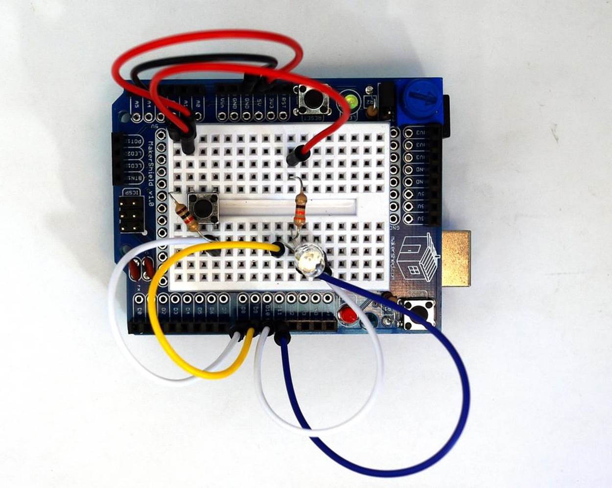
Figure 10-1. The Magic Light Bulb
Let’s Build a Magic Light Bulb
The Magic Light Bulb is an easy-to-build Arduino project using electronic parts from the Ultimate Microcontroller Pack. You can build the electronic circuit on a breadboard or the MakerShield. Building the Magic Light Bulb on the MakerShield allows the project to fit nicely in the palm of your hand, which offers great visual appeal for presentation to your friends. The wiring for the Magic Light Bulb can be constructed by using the Fritzing diagram shown in Figure 10-2.
Although the Fritzing diagram shows the breadboard and circuit components wired separately from the Arduino microcontroller, the project can easily be built on a MakerShield, as shown in Figure 10-1.
TECH NOTE
Check your wiring for errors using the Fritzing diagram before applying power to the circuit.
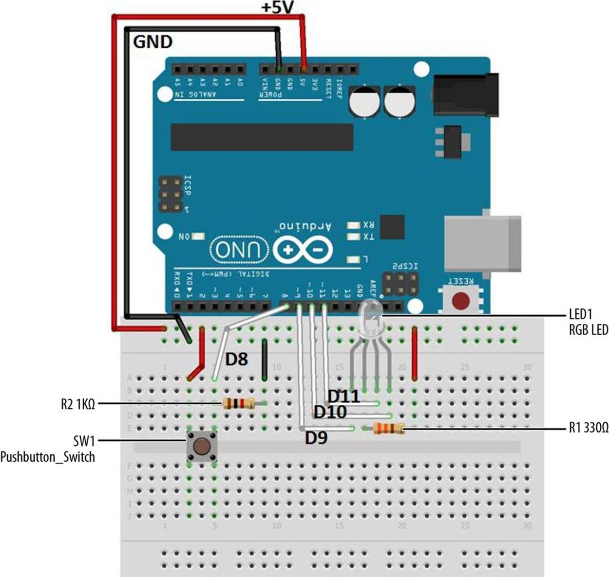
Figure 10-2. The Magic Light Bulb Fritzing diagram
Upload the Magic Light Bulb Sketch
With the Magic Light Bulb circuit built on the MakerShield, it’s time to upload the sketch. Example 10-1 operates the RGB LEDs using a mini pushbutton switch. Here are the steps you’ll need to follow:
1. Attach the Arduino to your computer using a USB cable.
2. Open the Arduino software and type Example 10-1 into the software’s text editor.
3. Upload the sketch to the Arduino.
4. Press the mini pushbutton switch for a moment.
The Arduino will sequence the RGB LED tricolor pattern three times. Figure 10-3 shows the Magic Light Bulb in action.
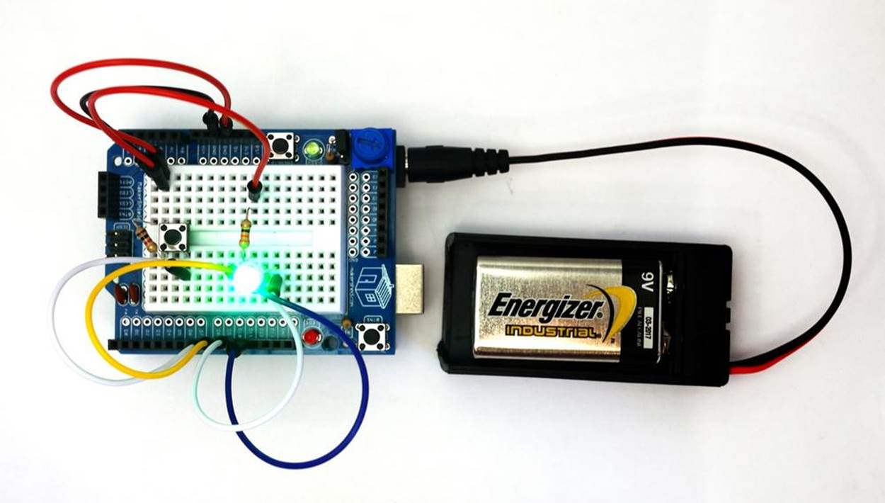
Figure 10-3. The Magic Light Bulb running through the tricolor pattern
Example 10-1. The Magic Light Bulb sketch
/*
Magic Light Bulb
Flashes the red, green, and blue LEDs of an RGB LED three times by
briefly pressing a mini pushbutton switch.
25 Feb 2013
Don Wilcher
*/
// Pushbutton switch and RGB pins wired to the Arduino microcontroller.
// give them names:
int redled = 9;
int grnled = 10;
int bluled = 11;
int Pbutton = 8;
// initialize counter variable
int n =0;
// monitor pushbutton switch status:
int Pbuttonstatus = 0;
// the setup routine runs once when you press reset:
void setup() {
// initialize the digital pins as outputs:
pinMode(redled, OUTPUT);
pinMode(grnled, OUTPUT);
pinMode(bluled, OUTPUT);
// initialize the digital pin as an input:
pinMode(Pbutton, INPUT);
// turn RGB outputs off:
digitalWrite(redled, HIGH);
digitalWrite(grnled, HIGH);
digitalWrite(bluled, HIGH);
}
// the loop routine runs 3x after the pushbutton is pressed:
void loop() {
Pbuttonstatus = digitalRead(Pbutton); // read pushbutton status
if(Pbuttonstatus == HIGH) { // if it's HIGH, start RGB Flasher
for (n = 0; n < 3; n++){ // flash RGB LEDs 3x
digitalWrite(redled, LOW); // turn the red LED on (LOW is on)
delay(250); // wait for a 1/4 second
digitalWrite(redled, HIGH); // turn the LED off (HIGH is off)
delay(250); // wait for a 1/4 second
digitalWrite(grnled, LOW); // turn the green LED on
delay(250); // wait for a 1/4 second
digitalWrite(grnled, HIGH); // turn the green LED off
delay(250); // wait for a 1/4 second
digitalWrite(bluled, LOW); // turn the blue LED on
delay(250); // wait for a 1/4 second
digitalWrite(bluled, HIGH); // turn the blue LED off
delay(250); // wait for a 1/4 second
}
}
else{ // if pushbutton is LOW, turn LEDs off
digitalWrite(redled, HIGH);
digitalWrite(grnled, HIGH);
digitalWrite(bluled, HIGH);
}
}
TROUBLESHOOTING TIP
If the LEDs don’t turn on in the proper sequence, check your sketch pin assignments as well as the orientation of the component on the MakerShield mini breadboard.
THE FOR LOOP AND COUNTERS
When you briefly press the mini pushbutton switch, the RGB cycles its color sequence three times before turning off. A “for” loop is behind the magic. Here’s the Arduino sketch code:
for (n = 0; n < 3; n++)
How does it work? The counter starts at zero (n = 0) and checks to see if the count value is less than 3 (n < 3). If the counter is less than 3, the counter adds one to itself (n++) to get the next count value. When the counter reaches a value of 3, the Arduino turns off the RGB LED.
Change the “3” to a “4” in the preceding code, and observe the RGB LED after uploading the modified sketch to the Arduino. Remember to record your observations and modified sketches into your lab notebook!
Circuit Theory
The Arduino controls the tricolor pattern that is sent to the RGB LED, as shown in Example 10-1. The RGB LED sequence or pattern is started with a short press of the mini pushbutton switch. Within the sketch is a counter that plays the pattern for a set number of times (in this case, three times). The replay number can easily be changed by replacing the counter’s value of 3 to a different number.
The block diagram in Figure 10-4 shows the building blocks and the electrical signal flow for the Magic Light Bulb. Circuit schematic diagrams are used by electrical engineers to quickly build cool electronic devices. The equivalent circuit schematic diagram for the Magic Light Bulb is shown in Figure 10-5.
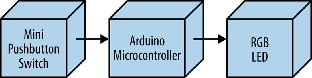
Figure 10-4. The Magic Light Bulb block diagram
Something to Think About
What happens to the Magic Light Bulb if the mini pushbutton switch is pressed continuously?
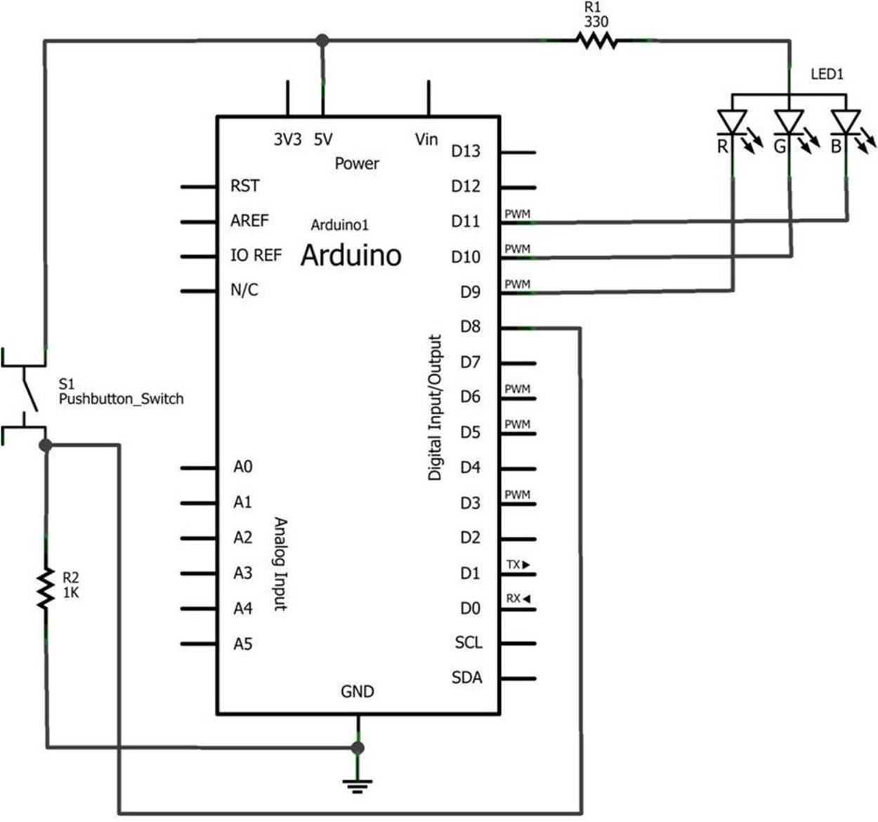
Figure 10-5. The Magic Light Bulb circuit schematic diagram
All materials on the site are licensed Creative Commons Attribution-Sharealike 3.0 Unported CC BY-SA 3.0 & GNU Free Documentation License (GFDL)
If you are the copyright holder of any material contained on our site and intend to remove it, please contact our site administrator for approval.
© 2016-2026 All site design rights belong to S.Y.A.