Make: Basic Arduino Projects - 26 Experiments with Microcontrollers and Electronics (2014)
Chapter 8. Tilt Flasher
Up-Down Sensor
In Chapter 4, the FrankenBot toy illustrated the method of flashing two LEDs wired in parallel. The Arduino microcontroller made it easy to change the flash rate of two LEDs using a 10KΩ potentiometer. How cool would it be to control an LED’s flash rate by moving an electronic box in an up-down motion? This project is a small window into the inner workings of gesture controls used to operate video games, robots, and electronic toys using simple body motions. Now we’re going to build and use orientation control, in the form of a tilt switch, to operate an Arduino flasher. The parts for the project consist of a tilt control switch, three resistors, and two LEDs. Figure 8-1 shows the Up-Down Sensor block diagram. You will find all of these electronic parts in the Ultimate Microcontroller Pack.
Parts List
§ Arduino microcontroller
§ MakerShield kit
§ S1: tilt control switch
§ R1: 1KΩ resistor (brown, black, red stripes)
§ R2: 330Ω resistor (orange, orange, brown stripes)
§ R3: 330Ω resistor (orange, orange, brown stripes)
§ LED1: green LED
§ LED2: red LED
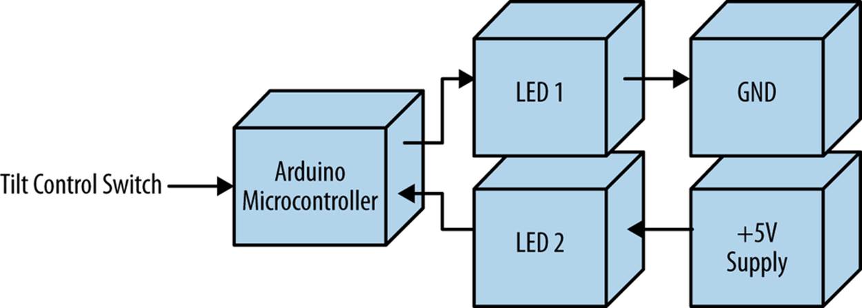
Figure 8-1. The Up-Down Sensor block diagram
TECH NOTE
A tilt control switch is sometimes called a tilt sensor.
Circuit Theory
As shown in Figure 8-1, the LED wiring is quite different from previous projects, because an electrical ground and a +5V battery are used to individually operate them. The idea behind this wiring technique is to allow one LED to be on at all times. The circuit schematic diagram in Figure 8-2on the left shows LED1 on while LED2 is off. The DPDT (double pole, double throw) switch upper contacts are open with the bottom contacts closed. The closed contacts allow current from the battery (+5V) to flow through the LED (LED1) turning it on. The open contacts turn off LED2 because no battery current is flowing through it. The Arduino microcontroller will use this DPDT switching method for the Up-Down Sensor project to operate two LED orientation indicators.
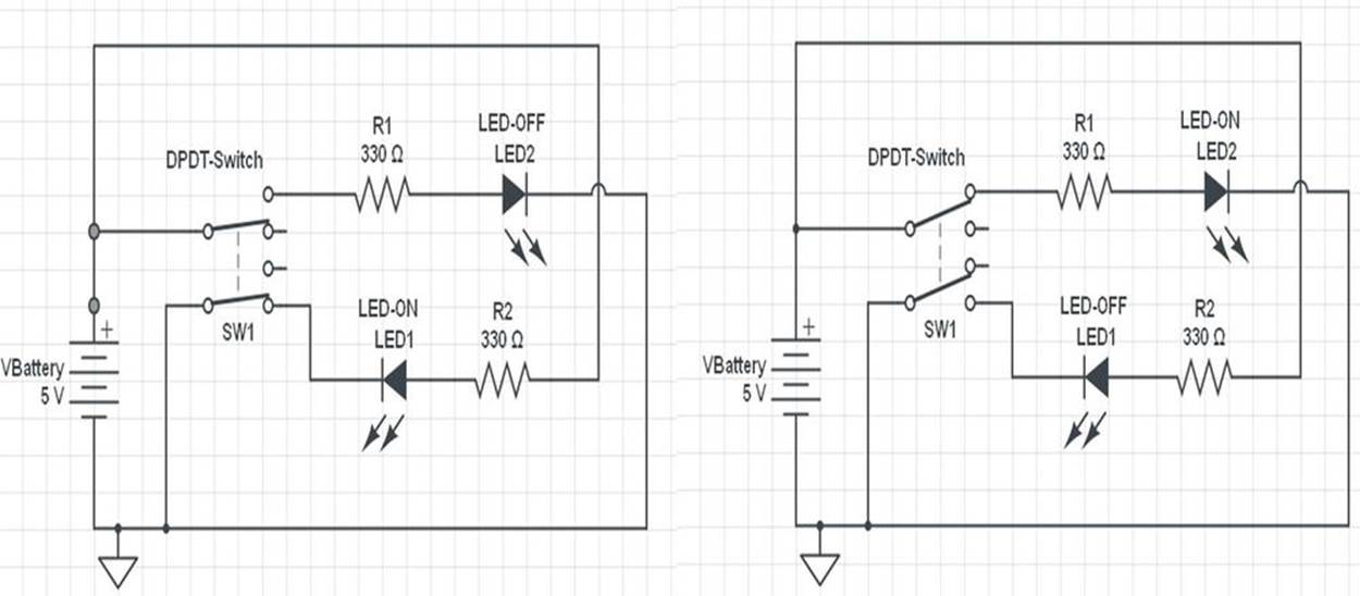
Figure 8-2. Circuit schematic diagram for a DPDT switch toggling two LEDs
TECH NOTE
Current is the movement or flow of electric charge.
The Up-Down Sensor
A simple Arduino microcontroller flasher can easily be turned into an Up-Down Sensor by adding a tilt control switch. As shown in Figure 8-3, the tilt control sensor is mounted on the MakerShield. When the tilt control switch is in the horizontal position, both the red and green LEDs will flash. Placing the MakerShield on its side will rotate the tilt control switch to vertical. The red LED will turn off and the green LED will be on but not flashing. Rotating the MakerShield back to the horizontal position causes the red and green LEDs to resume flashing. You can use either the Fritzing diagram shown in Figure 8-4 or the circuit schematic diagram in Figure 8-5 to build the Up-Down Sensor.
TECH NOTE
Placing another tilt control switch on the MakerShield in a vertical position can provide back and forth detection for robotics projects.
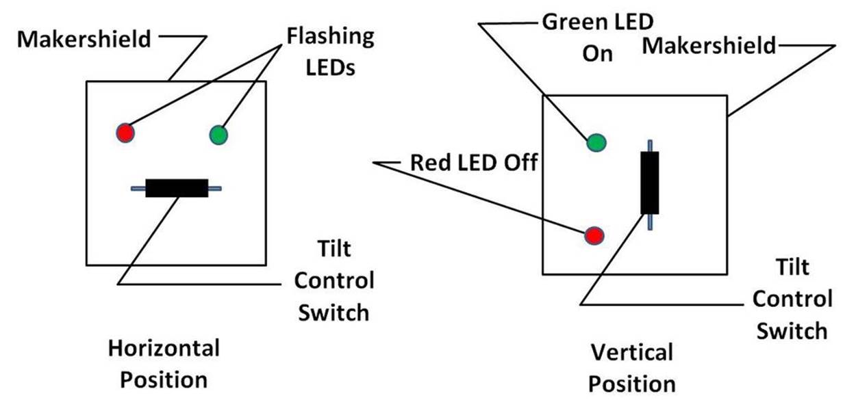
Figure 8-3. The Up-Down Sensor concept diagram
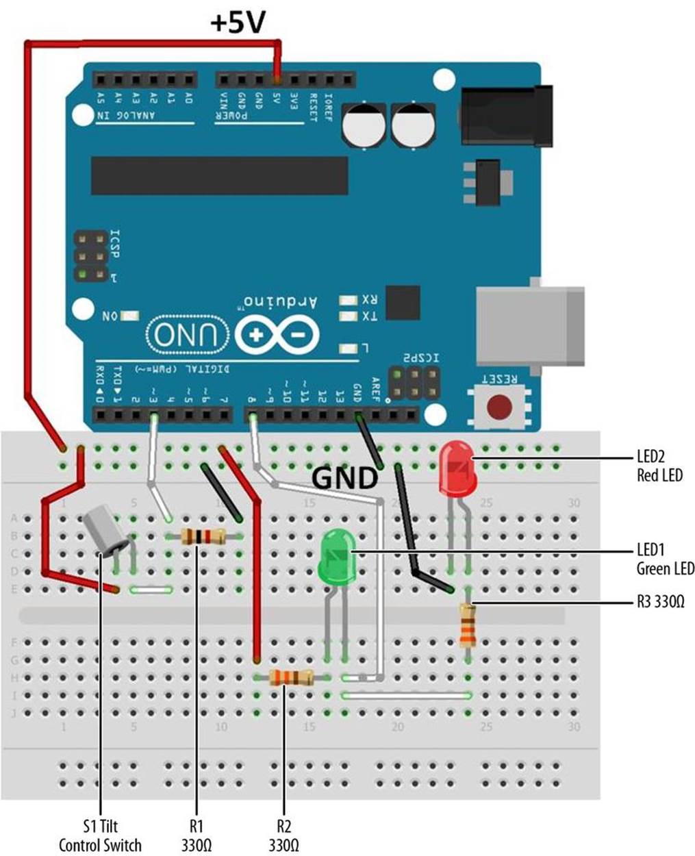
Figure 8-4. The Up-Down Sensor Fritzing diagram
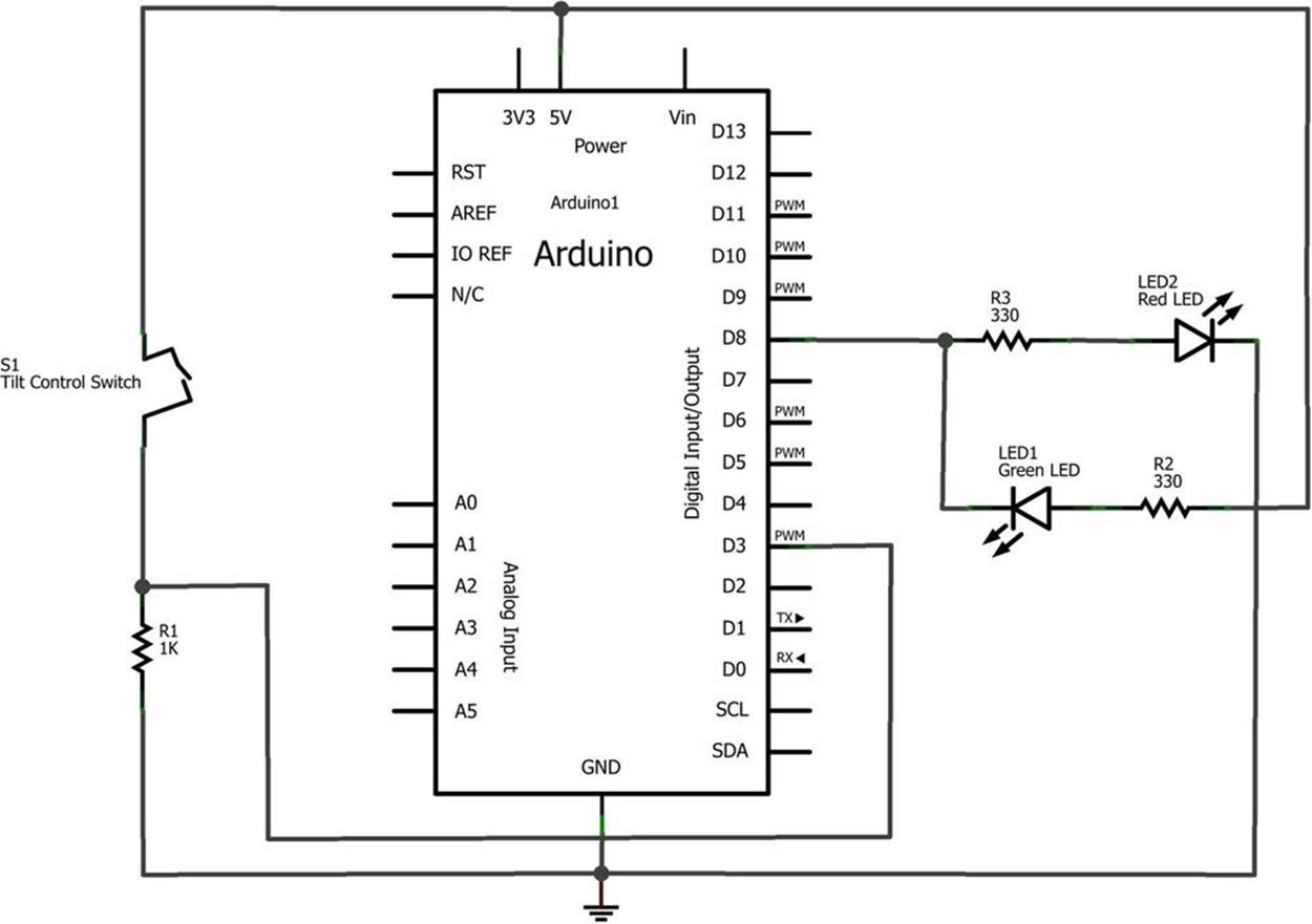
Figure 8-5. The Up-Down Sensor circuit schematic diagram
You can build the Up-Down Sensor on a MakerShield, as shown in Figure 8-6. The MakerShield allows you to carry it in a shirt pocket, computer bag, or purse for convenience. Example 8-1 can be uploaded to the Arduino after entering the code into the IDE’s text editor screen.
Example 8-1. Up-Down Sensor sketch
/*
Up-Down Sensor with Flashing LEDs
Flashes green and red LEDs at pin 8 when the tilt control
switch attached to pin 3 is tilted. The green LED wired to
pin 8 turns turns solid when no tilt condition is detected.
05 Feb 2013
Don Wilcher
*/
// constants won't change; they're used here to
// set pin numbers:
const int tiltPin = 3; // the number of the tilt control switch pin
const int ledPin = 8; // the number of the LED pin
// variables will change:
int tiltState = 0; // variable for tilt control switch status
void setup() {
pinMode(ledPin, OUTPUT);
// initialize the tilt control switch pin as an input:
pinMode(tiltPin, INPUT);
}
void loop(){
// read the state of the tilt control switch value:
tiltState = digitalRead(tiltPin);
// check if the tilt control switch contacts are closed
// if they are, the tiltState is HIGH:
if (tiltState == HIGH) {
// turn Red LED on;
digitalWrite(ledPin, HIGH);
// wait 100ms:
delay(100);
// turn LED off:
digitalWrite(ledPin,LOW);
// wait 100ms:
delay(100);
}
else {
// turn LED off:
digitalWrite(ledPin, LOW);
}
}
After uploading the Up-Down Sensor sketch to the Arduino microcontroller, orient the MakerShield so that the tilt control switch is horizontal. The red and green LEDs should be flashing. Next, rotate the MakerShield onto its side. The red LED will be off and the green LED will be on. Experiment with different MakerShield orientations and notice the response of the LEDs. Remember to record your observations in your lab notebook!
TROUBLESHOOTING TIP
If the LEDs don’t turn on after uploading the sketch to the Arduino microcontroller, check that the correct output pin is being used. Also, check to see that the LEDs are wired up properly, with the short wires connected to GND.
Something to Think About
How can the Up-Down Sensor be used to turn a small electric DC motor on and off?
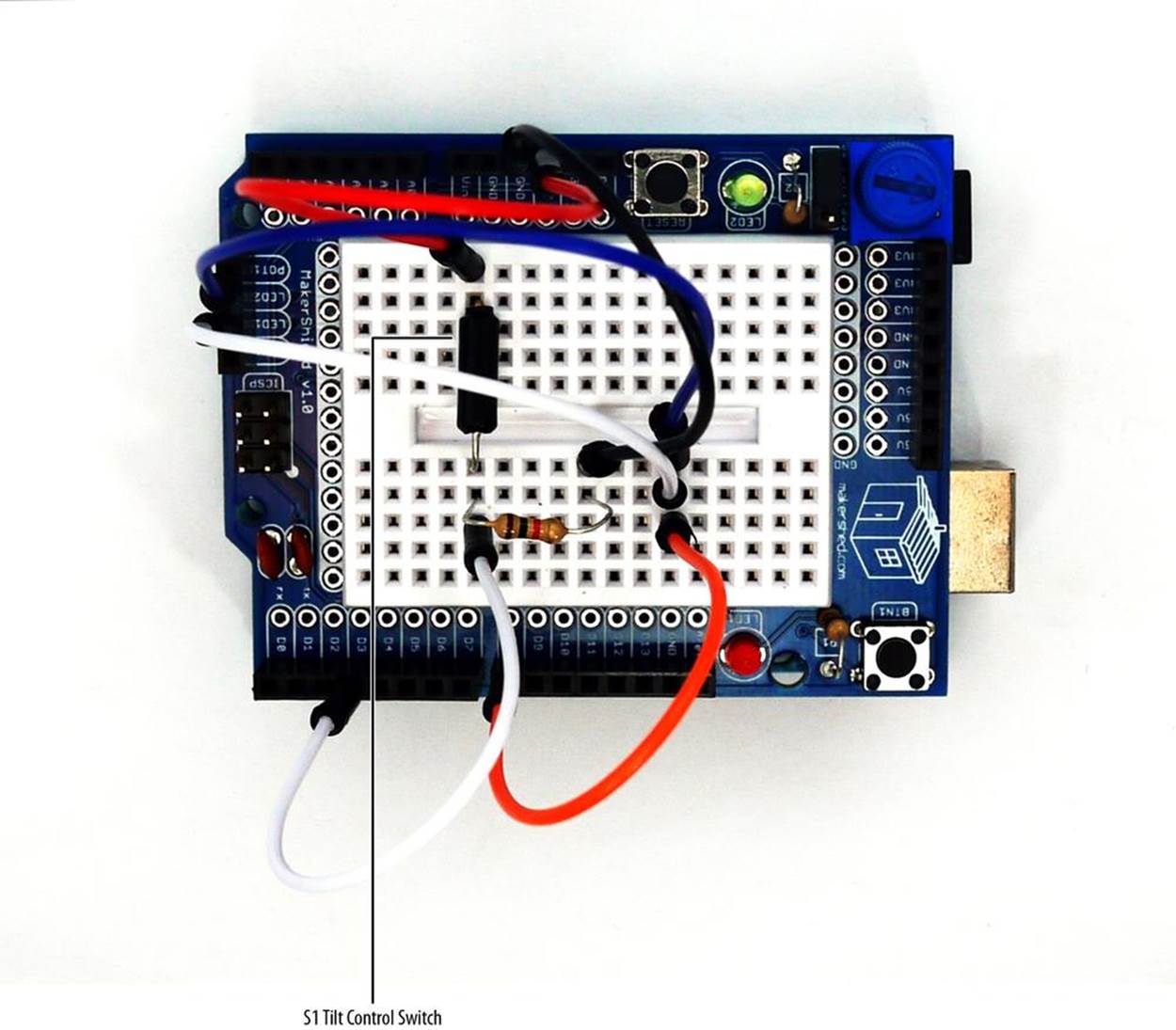
Figure 8-6. The Up-Down Sensor built on a MakerShield
All materials on the site are licensed Creative Commons Attribution-Sharealike 3.0 Unported CC BY-SA 3.0 & GNU Free Documentation License (GFDL)
If you are the copyright holder of any material contained on our site and intend to remove it, please contact our site administrator for approval.
© 2016-2026 All site design rights belong to S.Y.A.