Make: Basic Arduino Projects - 26 Experiments with Microcontrollers and Electronics (2014)
Chapter 11. Metal Checker: The Electronic Switch
An Electronic Tester
Have you noticed household objects that appear to be made of metal when they’re not? You and a friend can build an instrument that checks the metal properties of household objects in your home using an Arduino and a few electronic parts. The Arduino Metal Checker emits a tone when a metal object is placed across its test probes. With this awesome electronic instrument, you and a friend can uncover the metal mysteries hidden inside of your home. The Metal Checker uses an Arduino, two fixed resistors, one transistor, and a piezo buzzer. The Ultimate Microcontroller Pack makes it convenient to build the instrument because of the variety of electronic parts. The Metal Checker is shown in Figure 11-1.
Parts List
§ Arduino microcontroller
§ MakerShield kit
§ Q1: 2N3904 NPN transistor
§ R1: 330Ω resistor (orange, orange, brown stripes)
§ R2: 1KΩ resistor (brown, black, red stripes)
§ PB1: piezo buzzer
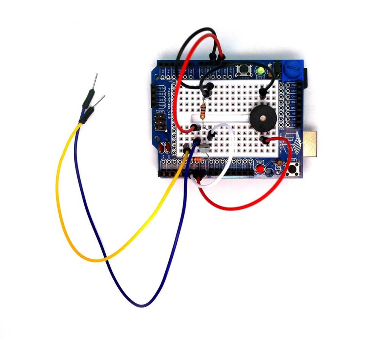
Figure 11-1. The Metal Checker device
Let’s Build a Metal Checker
The Metal Checker is a cool electronics device to build with an Arduino and electronic parts from the Ultimate Microcontroller Pack. You can build the electronic circuit on an ordinary breadboard or the MakerShield. Building the Metal Checker on the MakerShield allows the device to fit nicely inside a Maker’s toolbox or workbench drawers. Also, the MakerShield is small enough to carry with you in the field for scientific metal checking activities. Figure 11-2 provides a Fritzing diagram for building the Metal Checker.
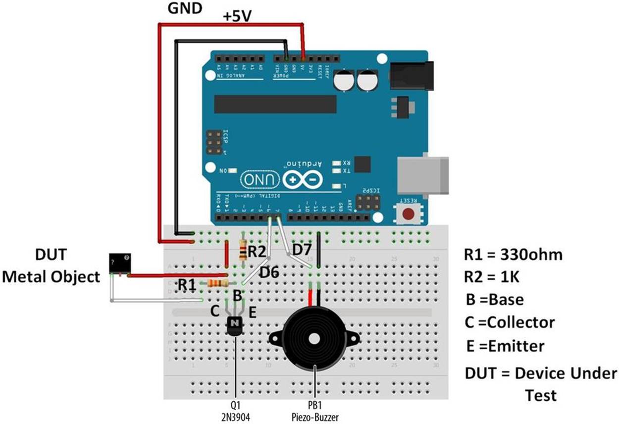
Figure 11-2. The Metal Checker Fritzing diagram
WHY USE A TRANSISTOR AND ARDUINO FOR A METAL CHECKER?
A simple Metal Checker can easily be built using an LED, a battery, and wire. So why bother using an Arduino and a transistor? Based on the metal’s electrical conductive properties, the transistor’s external base resistor will set an appropriate sensing current to turn the transistor on. The transistor provides an approximate voltage value of +5VDC to the Arduino. Upon detecting the +5VDC signal, the Arduino turns on the piezo buzzer. Therefore, the transistor acts as an electronic switch, sensitive to certain amounts of electrical current flowing through the metal. The electronic switching and sensing functions can be adjusted based on the type of metal. Also, different piezo buzzer sounds can be programmed into the Arduino to reflect various metals as well.
A simple Metal Checker cannot be modified to have such cool detecting features because of the limited parts used.
The Metal Checker uses a small transistor for metal sensing. To correctly wire it with the Arduino, Figure 11-3 shows a picture with the proper transistor pinout. Use both the Fritzing diagram and the transistor pinout to ensure correct attachment to the Arduino.
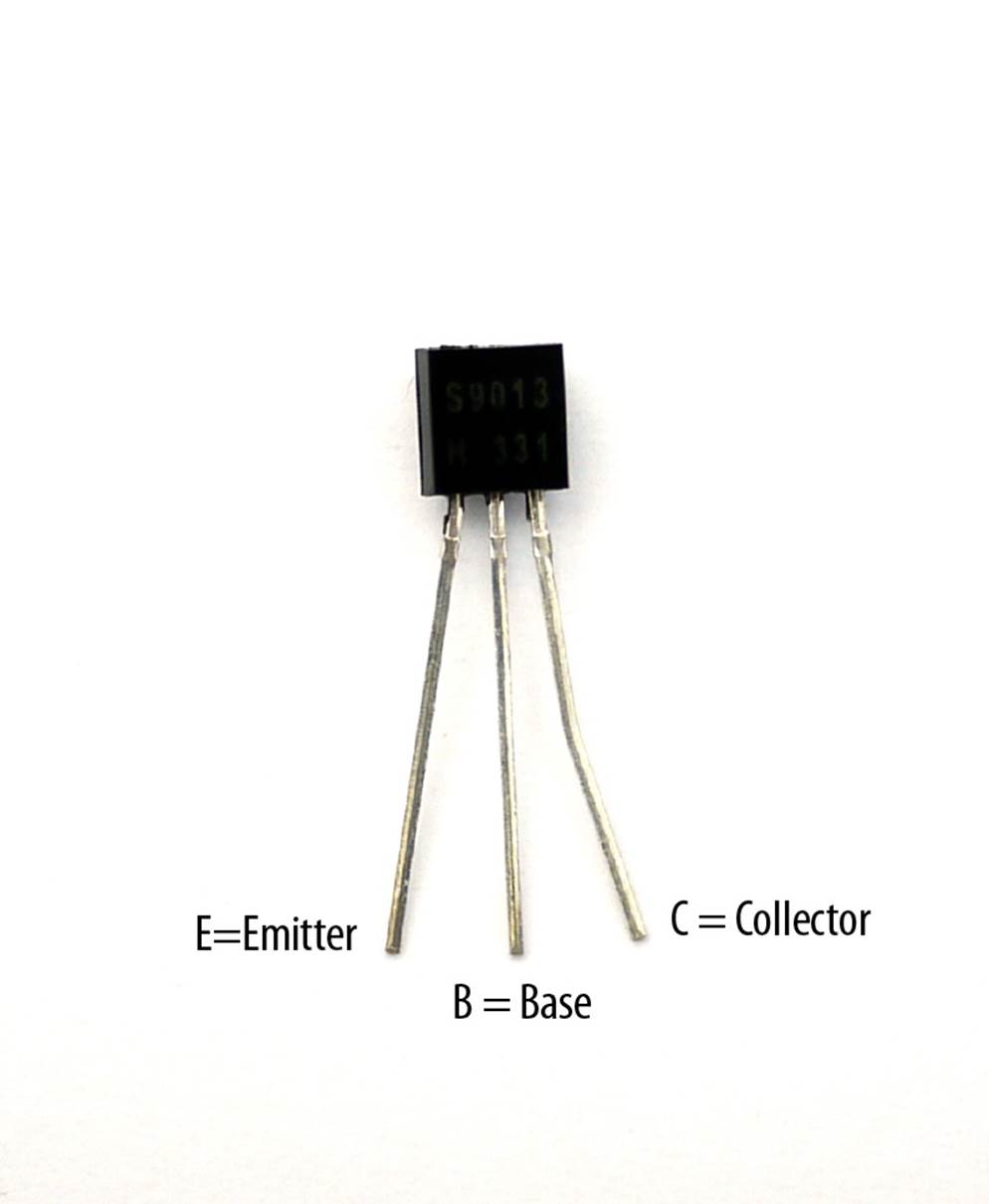
Figure 11-3. The 2N3904 NPN transistor pinout
Although the Fritzing diagram shows the breadboard and electronic components wired separately from the Arduino, the device can easily be built on a MakerShield, as shown in Figure 11-1.
TECH NOTE
Check your wiring for errors using the Fritzing diagram before applying power to the circuit.
Upload the Metal Checker Sketch
With the Metal Checker circuit built on the MakerShield, it’s time to upload the sketch. Example 11-1 operates the piezo buzzer using a small transistor. Here are the steps you’ll need to follow:
1. Attach the Arduino to your computer using a USB cable.
2. Open the Arduino software and type Example 11-1 into the software’s text editor.
3. Upload the sketch to the Arduino.
4. Touch the test probes together.
The Arduino will turn on the piezo buzzer. Now you’re ready to unlock the metal mysteries hiding in your house!
Example 11-1. The Metal Checker sketch
/*
Metal Checker
Turns on and off a piezo buzzer at pin 7 when metal is placed across
the sense wires of the metal sensor circuit attached to pin 6.
The circuit:
* Piezo buzzer attached from pin 7 to ground
* Metal Checker sensor attached to pin 7
* 1KΩ fixed resistor attached from pin 6 to ground
March 2013
by Don Wilcher
*/
// set pin numbers:
const int MSensePin = 6; // the number of the metal sense pin
const int PBuzzerPin = 7; // the number of the piezo buzzer pin
// variables will change:
int MetalStatus = 0; // variable for the metal sense status
void setup() {
// initialize the LED pin as an output:
pinMode(PBuzzerPin, OUTPUT);
// initialize the pushbutton pin as an input:
pinMode(MSensePin, INPUT);
}
void loop(){
// read the state of the metal sense value:
MetalStatus = digitalRead(MSensePin);
// check if metal is present
// if it is, the MetalStatus is HIGH:
if (MetalStatus == HIGH) {
// turn piezo buzzer on:
digitalWrite(PBuzzerPin, HIGH);
}
else {
// turn MetalStatus off:
digitalWrite(PBuzzerPin, LOW);
}
}
THE TRANSISTOR
The transistor is a small electronic component that can be used as an electronic switch or an amplifier. There are two types of transistors: NPN and PNP. These transistor types can be used as electronic switches and amplifiers: the current flow in the PNP transistor is opposite of that in the NPN transistor. The 2N3904 NPN transistor is being used as an electronic switch, replacing the mini pushbutton component of previous Arduino projects. To learn more about the transistor, read Charles Platt’s Make: Electronics (Maker Media, 2009).
TROUBLESHOOTING TIP
If the piezo buzzer doesn’t turn on, check your sketch pin assignments as well as the orientation of the transistor on the MakerShield mini breadboard.
Circuit Theory
The 2N3904 NPN transistor provides a signal to the Arduino, allowing it to turn on the piezo buzzer. Placing a metal object on the test probes allows electrical current to flow through the transistor, turning it on like a pushbutton switch. The 1KΩ (kilo-ohm) resistor provides a control voltage (+5VDC) to the Arduino, allowing it to turn on the piezo buzzer. Placing plastic objects on the test probes will not activate the transistor, the Arduino, and the piezo buzzer.
The block diagram in Figure 11-4 shows the building blocks and the electrical signal flow for the Metal Checker. A circuit schematic diagram used by electrical engineers to quickly build cool electronic devices is shown in Figure 11-5. Circuit schematic diagrams use electrical symbols for electronic components and are abbreviated drawings of Fritzing diagrams.
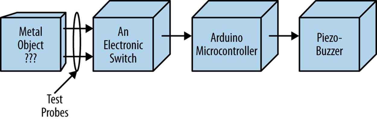
Figure 11-4. The Metal Checker block diagram
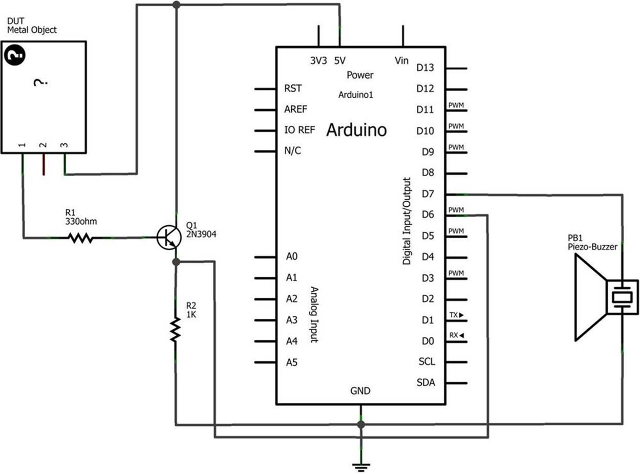
Figure 11-5. The Metal Checker circuit schematic diagram
Something to Think About
Can a Metal Checker be used as a continuity tester?
ELECTRICAL SAFETY TIP
Under no circumstance should the Metal Checker be used to test powered electrical/electronic devices. For your safety and the protection of the Arduino and MakerShield, do not use the Metal Checker to test any electrical/electronic devices!
All materials on the site are licensed Creative Commons Attribution-Sharealike 3.0 Unported CC BY-SA 3.0 & GNU Free Documentation License (GFDL)
If you are the copyright holder of any material contained on our site and intend to remove it, please contact our site administrator for approval.
© 2016-2026 All site design rights belong to S.Y.A.