Make: Basic Arduino Projects - 26 Experiments with Microcontrollers and Electronics (2014)
Chapter 12. The Theremin
A Simple Transistor Amplifier
Electronic circuits that produce audible sounds have been used to create strange and eerie audio effects for science-fiction movies like Star Wars and Marvel’s The Avengers. The Theremin is a device that generates different electronic sounds by waving hands over and around a pair of protruding antennas.
You can make your own awesome Theremin using a few electronic components from the Ultimate Microcontroller Pack. The Theremin in this project will not use a pair of antennas but a photocell to interact with the device. Also, a simple transistor amplifier will be built to enhance the volume of the electronic sounds created with your Theremin. The Parts List shows all of the electronic components available from the Ultimate Microcontroller Pack to build your own Theremin. The Theremin built on a MakerShield is shown in Figure 12-1.
Parts List
§ Arduino microcontroller
§ MakerShield kit
§ Q1: 2N3904 or S9013 NPN transistor
§ R1: 10KΩ resistor (brown, black, orange stripes)
§ R2: 1KΩ resistor (brown, black, red stripes)
§ SPKR1: mini 8Ω speaker
§ C1: 100 uF electrolytic capacitor
§ PC1: photocell
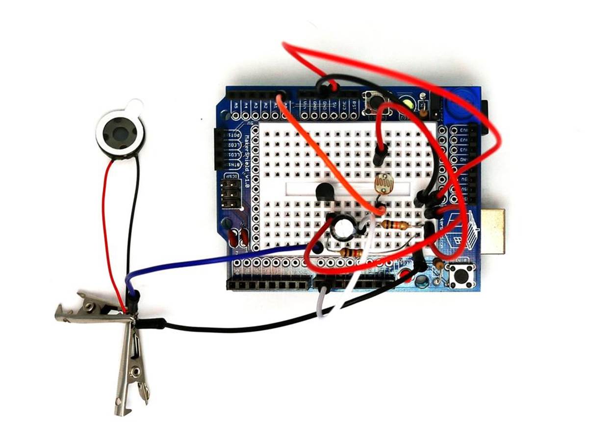
Figure 12-1. The Theremin
Let’s Build a Theremin
The Theremin, invented in 1920 by Russian inventor Leon Theremin, uses an electronic circuit called an oscillator to create different sounds. In our Theremin, we’re using the Arduino as an oscillator by programming it to select different tones based on changing light levels. The tone changes are made by waving your hand over a photocell, creating various sounds based on changing light levels. The circuit is built on a breadboard with electronic components from the Ultimate Microcontroller Pack, as just shown in the Parts List. Although the Theremin can be built on an ordinary breadboard, the MakerShield makes the device small enough to carry in a shirt pocket or Maker bag. Figure 12-2 shows a Fritzing diagram of the Theremin. Also, the actual mini 8Ω speaker used in the Theremin project is shown in Figure 12-3.
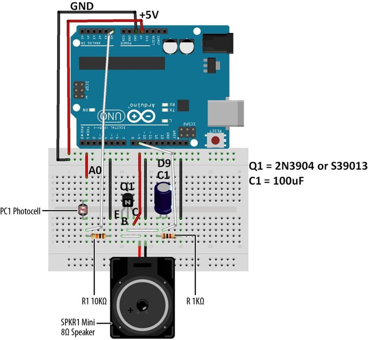
Figure 12-2. The Theremin Fritzing diagram
The electronic sounds generated by the Arduino are wired to a simple transistor amplifier. Pay close attention to the 100 uF electrolytic capacitor’s orientation (shown on the Fritzing diagram) to prevent damage to the Arduino. Also, the NPN transistor’s pinout for either a 2N3904 or S9013 electronic component is shown on the Fritzing diagram’s breadboard. The mini 8Ω speaker color wire leads must be connected correctly (as shown in Figure 12-2) in order for the audio electronic sounds to be heard through it.

Figure 12-3. The mini 8Ω speaker
TECH NOTE
The 100 uF electrolytic capacitor is called a polarized capacitor because of its positive and negative electrical leads. Like an LED, electricity flows through it easily in only one direction.
Upload the Theremin Sketch
It’s time to upload the sketch to the Arduino with the Theremin’s photocell and simple transistor amplifier circuits built on the MakerShield. Example 12-1 operates the Arduino-based Theremin using a photocell and a simple transistor amplifier circuit. Here are the steps you’ll need to follow:
1. Attach the Arduino to your computer using a USB cable.
2. Open the Arduino software and type Example 12-1 into the software’s text editor.
3. Upload the sketch to the Arduino.
Once the Theremin sketch has been uploaded to the Arduino, the mini 8Ω speaker will begin emitting an electronic buzzing sound. A wave of your hand over the photocell will change the tone coming from the speaker. With a small amount of light on the photocell, the tone’s pitch will decrease. Placing the Theremin under a light bulb increases the electronic sound’s pitch. Like the inventor Leon Theremin, now you’re ready to create some really cool sounds from your Arduino-powered Theremin. Remember to document your new designs and experiments in a lab notebook!
Example 12-1. The Theremin sketch
/*
Theremin
Plays sound effects through a simple transistor
amplifier using a photocell.
I/O circuits:
* A simple transistor amplifer wired to digital pin 8
* A photocell wired to analog 0 and +5V
* A 10K resistor wired to analog 0 pin to ground
*/
void setup() {
// initialize serial communications (for debugging only):
Serial.begin(9600);
}
void loop() {
// read the sensor:
int sensorReading = analogRead(A0);
// print the sensor reading so you know its range:
Serial.println(sensorReading);
// map the analog input range (in this case, 400–1000 from
// the photoresistor) to the output pitch range (120–1500 Hz)
// change the minimum and maximum input numbers below
// depending on the range your sensor's giving:
int thisPitch = map(sensorReading, 400, 1000, 120, 1500);
// play the pitch:
tone(9, thisPitch, 10);
delay(1); // delay in between reads for stability
}
TROUBLESHOOTING TIP
If the mini 8Ω speaker doesn’t emit sound, check your sketch for programming errors and also check the orientation of the transistor and the electrolytic capacitor on the MakerShield mini breadboard.
THE SERIAL MONITOR
Sometimes you may have to debug or troubleshoot a sketch because of programming errors. The Serial Monitor is an embedded tool of the Arduino software that allows you to display information from your program, such as data variables, on your computer screen. To display the data, use the simple Arduino instruction Serial.println(). The Theremin sketch uses this to display the photocell sensor data. As shown in Figure 12-4, the sketch instruction provides scrolling sensor data from the photocell to the Serial Monitor.
To access the data monitor, add the Serial.begin(9600) instruction within the void setup() function to open a communication link between your computer and the Arduino. The 9600 sets the speed at which the Arduino sends data to your computer. It means your Arduino is sending data to your computer at 9,600 bits every second. (Another term used to describe the data transmission speed is “Baud” rate.)
To display variables on the Serial Monitor, use the instruction Serial.print In(variable name).
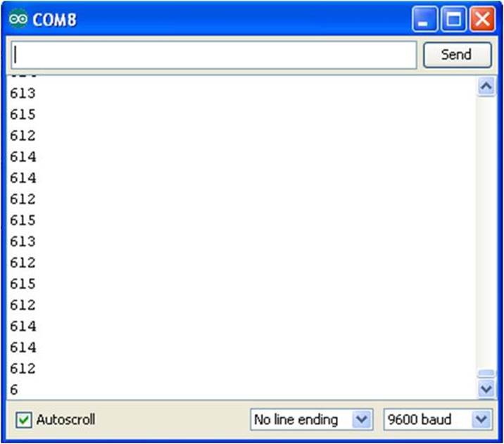
Figure 12-4. Photocell sensor data scrolling on the Serial Monitor
Circuit Theory
The 2N3904 or S39013 NPN transistor amplifies or increases the audio signal created by the Arduino. The transistor has an amplification value called “gain” used to determine the volume of an electrical signal. A typical gain value engineers use in designing simple amplifiers like this one is 100. The mini 8Ω speaker can be wired directly to pin D9 with a reasonable amount of volume, but the simple transistor amplifier increases the sound by a factor of 100, making the Theremin sound louder.
The block diagram in Figure 12-5 shows the building blocks and the electrical signal flow for the Theremin. A Fritzing software circuit schematic diagram of the Theremin is shown in Figure 12-6. As a reminder, circuit schematic diagrams use electrical symbols for electronic components and are abbreviated drawings of Fritzing diagrams.
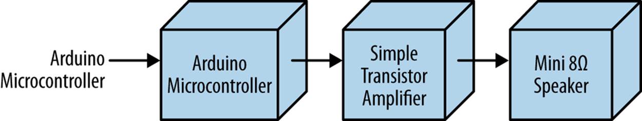
Figure 12-5. The Theremin block diagram
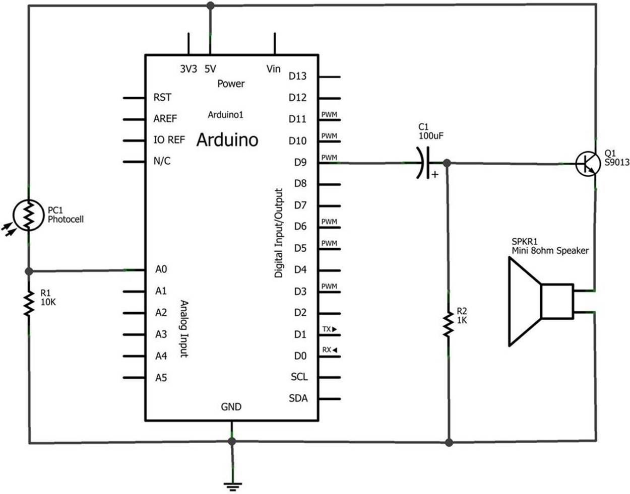
Figure 12-6. The Theremin circuit schematic diagram
Something to Think About
What sounds would be emitted by the Theremin’s simple transistor amplifier if the mini 8Ω speaker was replaced with a piezo buzzer? Try it!
All materials on the site are licensed Creative Commons Attribution-Sharealike 3.0 Unported CC BY-SA 3.0 & GNU Free Documentation License (GFDL)
If you are the copyright holder of any material contained on our site and intend to remove it, please contact our site administrator for approval.
© 2016-2026 All site design rights belong to S.Y.A.