Make: Basic Arduino Projects - 26 Experiments with Microcontrollers and Electronics (2014)
Chapter 14. The LCD News Reader
Have you ever wondered what cool projects you can build with the Ultimate Microcontroller Pack LCD (liquid crystal display)? So far in this book, the Arduino has communicated with us via sound, via blinking LEDs, and via the Serial Monitor. What would it be like if the Arduino could communicate through a self-contained screen that could display two lines of text at a time? This project is all about using the LCD to display information in characters made of letters, numbers, and a few special symbols. You can make the information scroll and reverse, and you can even do some very simple animations! We start learning about the LCD in Figure 14-1.
Parts List
§ Arduino microcontroller
§ Full-size clear breadboard
§ R1: 10KΩ potentiometer
§ LCD1: LMB162ABC 16x2 LCD
§ 16-pin male header (electrical connector)
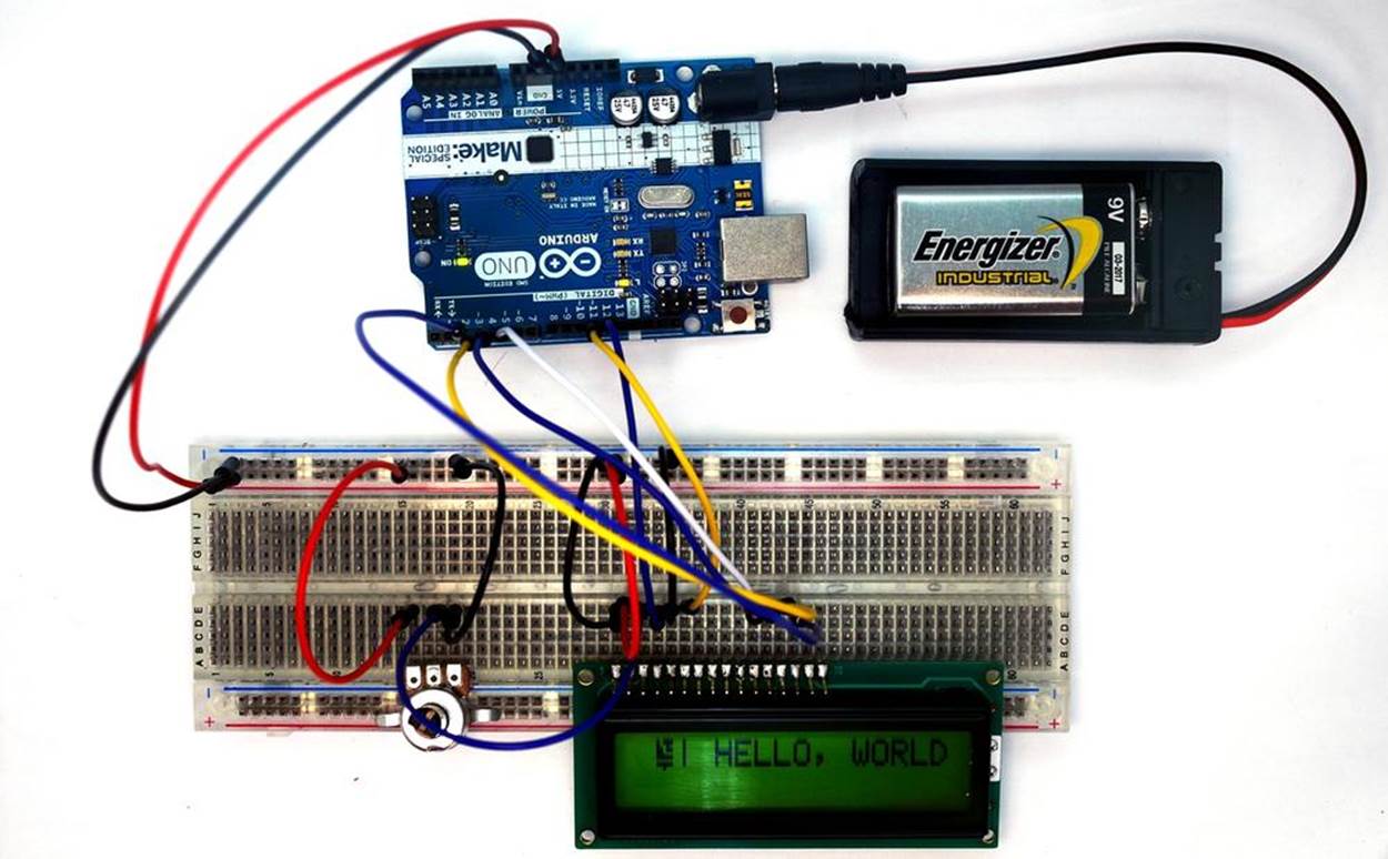
Figure 14-1. The LCD News Reader
Let’s Build the LCD
The first task in building the LCD News Reader is to solder a 16-pin male header to the LCD. The Ultimate Microcontroller Pack has several male headers for building your own Arduino shields. The header needs to be cut to a length to match the 16 LCD copper pad holes. Figure 14-2 shows the male header cut to the appropriate LCD length. Insert the 16-pin male header through the copper pad holes and solder them one by one to the LCD printed circuit board (PCB). Figure 14-3 shows the male header soldered onto the LCD PCB.
Place the LCD onto the solderless breadboard, as shown in Figure 14-4. Wire LCD pin number “1” to ground and “2” to +5VDC. Attach the center pin of the 10KΩ potentiometer to pin number “3” of the LCD. Wire the remaining 10KΩ potentiometers pins to +5VDC and ground as shown in the diagram. With the LCD wired to the solderless breadboard, apply power to it using the Arduino. Adjust the 10KΩ potentiometer until the LCD’s top row displays pixel squares, as shown in Figure 14-4. Complete the rest of the tester wiring using the Fritzing diagram shown in Figure 14-5.
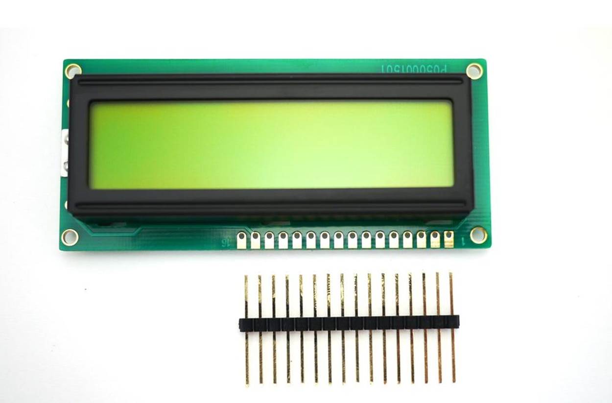
Figure 14-2. The 16-pin male header cut to match the length of the LCD copper pad holes
TECH NOTE
A header is an electrical connector.
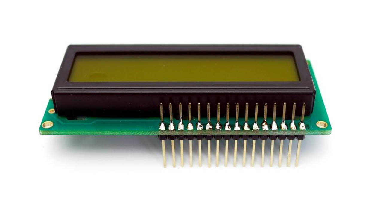
Figure 14-3. Male header soldered onto the LCD PCB
TECH NOTE
A special board with electronic components soldered to copper pads and traces is called a printed circuit board (PCB).
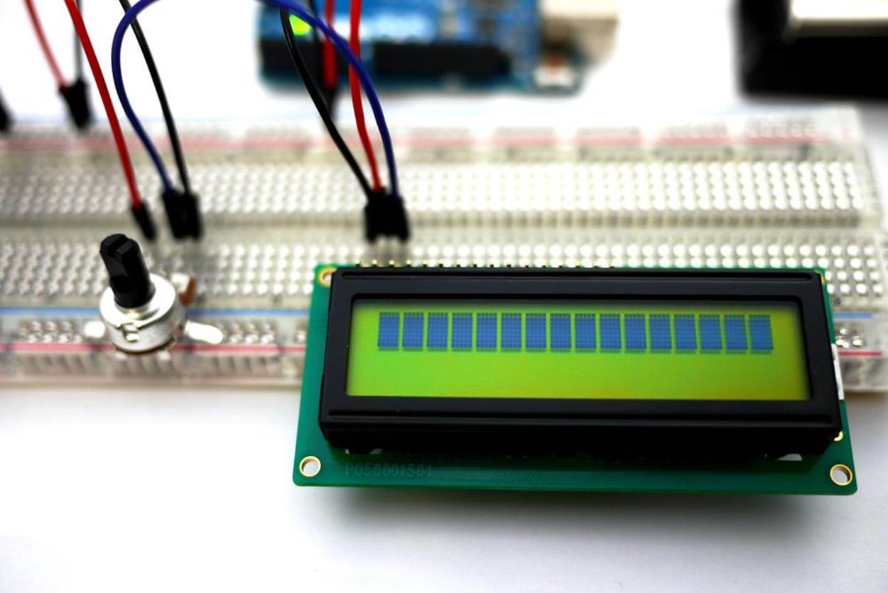
Figure 14-4. Testing the LCD wiring on a full-size clear breadboard
Upload the LCD News Reader Sketch
It’s time to upload the sketch for the LCD News Reader to the Arduino. Here are the steps you’ll need to follow:
1. Attach the Arduino to your computer using a USB cable.
2. Open the Arduino software and type Example 14-1 into the software’s text editor.
3. Upload the sketch to the Arduino.
Once the LCD News Reader sketch has been uploaded to the Arduino, the LCD will display a message, as shown in Figure 14-1. According to computing tradition, the first message you should display on a new piece of hardware is “Hello, World!” Figure 14-6 shows the LCD News Reader displaying various screens.
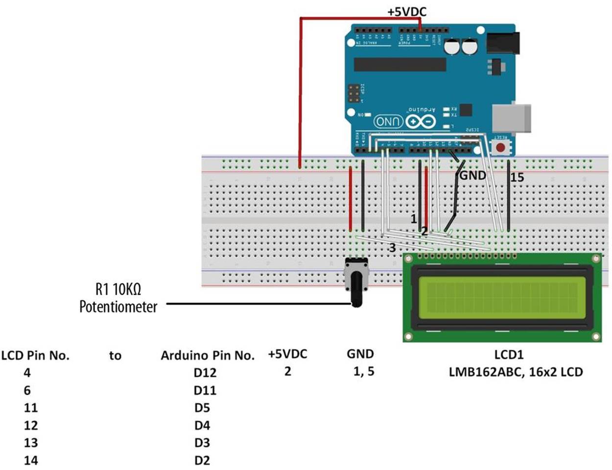
Figure 14-5. The LCD News Reader Fritzing diagram
Example 14-1. The LCD News Reader sketch
/*
The LCD News Reader
20 August 2013
*/
// include the LCD library code:
#include <LiquidCrystal.h>
// set up pins on Arduino for LCD and test lead
LiquidCrystal lcd(12,11,5,4,3,2);
// set up the LCD's number of columns and rows
#define Xdelay 1900
String a;
String b;
String c;
String d;
void setup() {
lcd.begin(16,2);
lcd.setCursor(0,0);
clearLCD();
backlightOn();
lcd.print("HELLO, WORLD!");
delay(Xdelay);
}
void loop()
{
char databuff[16];
char dispbuff[16];
// display on/off test
for(int x = 5; x>0; x--)
{
delay(1000);
displayOff();
delay(1000);
displayOn();
}
clearLCD();
backlightOn();
lcd.print("SLOW FADE ");
fadeOut(100);
fadeIn(10);
// light up all segments as a test
lcd.print("0123456789abcdef");
delay(Xdelay);
lcd.print("ghijklmnopqrstuv");
delay(Xdelay);
lcd.print("wxyz +?*&%$#()!=");
delay(Xdelay);
lcd.print(" ");
delay(Xdelay);
lcd.print(" ");
delay(Xdelay);
a = "0123456789abcdef";
b = "ghijklmnopqrstuv";
c = "wxyz +?*&%$#()!=";
d = " ";
selectLineTwo();
lcd.print(a);
delay(Xdelay);
selectLineOne();
lcd.print(a);
selectLineTwo();
lcd.print(b);
delay(Xdelay);
selectLineOne();
lcd.print(b);
selectLineTwo();
lcd.print(c);
delay(Xdelay);
selectLineOne();
lcd.print(c);
selectLineTwo();
lcd.print(d);
delay(Xdelay);
selectLineOne();
lcd.print(d);
selectLineTwo();
lcd.print(d);
delay(Xdelay);
for (int x = 0; x<=5; x++)
{
for(int i = 15; i>=0; i--)
{
goTo(i);
if (i%4 == 1)
lcd.print("- ");
if (i%4 == 2)
lcd.print("I ");
if (i%4 == 3)
lcd.print("- ");
if (i%4 == 0)
lcd.print("I ");
delay(100);
}
for(int i =0; i<=14; i++)
{
goTo(i);
lcd.print(" @");
delay(100);
}
}
clearLCD();
}
void selectLineOne()
{
lcd.write(0xFE); //command flag
lcd.write(128); //position
delay(10);
}
void selectLineTwo()
{
lcd.write(0xFE); //command flag
lcd.write(192); //position
delay(10);
}
void goTo(int position)
{
if (position<16)
{
lcd.write(0xFE); //command flag
lcd.write((position+128)); //position
}else if (position<32)
{
lcd.write(0xFE); //command flag
lcd.write((position+48+128)); //position
} else { goTo(0); }
delay(10);
}
void clearLCD()
{
lcd.write(0xFE); //command flag
lcd.write(0x01); //clear command
delay(10);
}
void backlightOn()
{
lcd.write(0x7C); //command flag for backlight stuff
lcd.write(157); //light level
delay(10);
}
void backlightOff()
{
lcd.write(0x7C); //command flag for backlight stuff
lcd.write(128); //light level for off
delay(10);
}
void backlightValue(int bv)
{
int val = bv;
if (bv < 128) val= map(bv, 0, 1023, 128, 157);
if (bv > 157) val = map(bv, 0, 1023, 128, 157);
lcd.write(0x7C); //command flag for backlight stuff
lcd.write(val); //light level
delay(10);
}
void displayOn()
{
lcd.write(0xFE); //command flag
lcd.write(0x0C); //clear command
delay(10);
}
void displayOff()
{
lcd.write(0xFE); //command flag
lcd.write(0x08); //clear command
delay(10);
}
void fadeOut(int fade)
{
for (int x = 157; x>128; x--)
{
backlightValue(x);
delay(fade);
}
}
void fadeIn(int fade)
{
for (int x = 128; x<=157; x++)
{
backlightValue(x);
delay(fade);
}
}
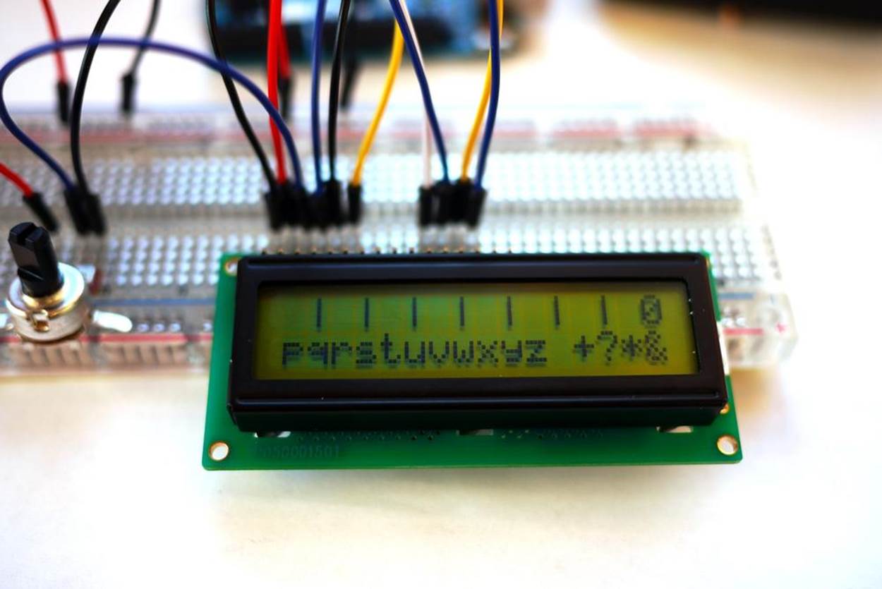
Figure 14-6. The LCD News Reader displaying various screens
TECH NOTE
A 16x2 LCD has two rows capable of displaying 16 characters each.
Circuit Theory
Example 14-1 displays a variety of characters, letters, and numbers based on C language programming instructions. The sketch is programmed to test all segments of the LCD as it cycles through the Arduino program. The Arduino sketch uses digital data pins D2, D3, D4, D5, D11, and D12 of its microcontroller chip to send text message information to the LCD. Time delays programmed into the sketch allow the characters, letters, and numbers to be displayed continuously on the LCD. The 10K potentiometer lets you adjust the contrast of the display.
The block diagram in Figure 14-7 shows the building blocks and the electrical signal flow for the LCD News Reader. Circuit schematic diagrams are used by electrical engineers to quickly build cool electronic devices. The equivalent circuit schematic diagram for the LCD News Reader is shown in Figure 14-8.
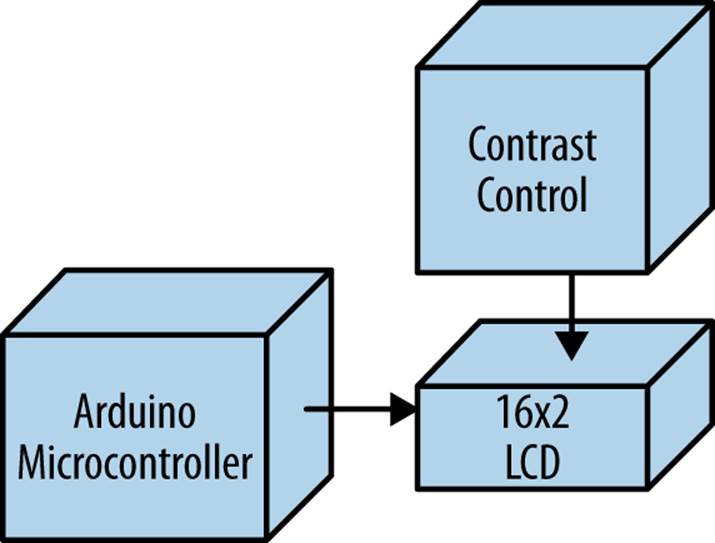
Figure 14-7. The LCD News Reader block diagram
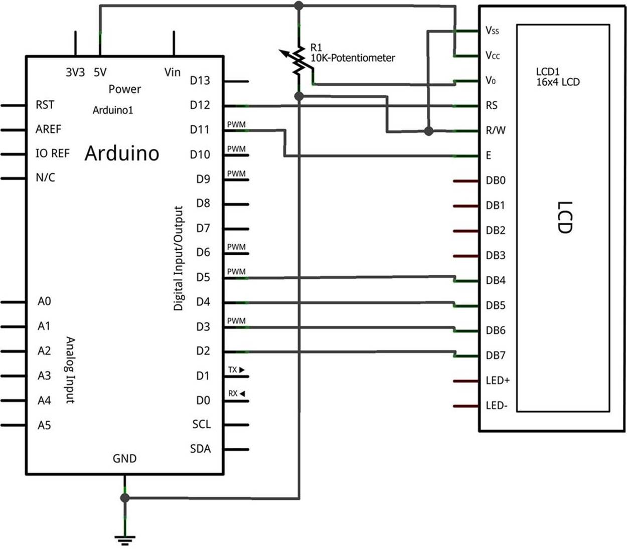
Figure 14-8. The LCD News Reader circuit schematic diagram
Something to Think About
How can a pushbutton switch be used to control the display?
All materials on the site are licensed Creative Commons Attribution-Sharealike 3.0 Unported CC BY-SA 3.0 & GNU Free Documentation License (GFDL)
If you are the copyright holder of any material contained on our site and intend to remove it, please contact our site administrator for approval.
© 2016-2026 All site design rights belong to S.Y.A.