Make: Basic Arduino Projects - 26 Experiments with Microcontrollers and Electronics (2014)
Chapter 15. A Logic Tester (with an RGB LED)
The NOT, AND, and OR projects (Chapters 5, 6, and 7, respectively) use two basic voltages: either +5VDC for TRUE or 0V for FALSE. These two signals let the Arduino make basic logic decisions. In the computer world, these voltages are known as binary data. In computers, binary data is represented by logic “1” (+5 volts DC) and logic “0” (0 volts). You can build a cool electronic device to see binary data using a few electronic components from the Ultimate Microcontroller Pack. The electronic components to build this device are shown in the Parts List. The Logic Tester with an RGB LED is shown in Figure 15-1.
Parts List
§ Arduino microcontroller
§ MakerShield kit
§ R1: 1KΩ resistor (brown, black, red stripes)
§ R2: 330Ω resistor (orange, orange, brown stripes)
§ PB1: pushbutton switch
§ LED1: RGB (red, green, blue) LED
§ Long test wire
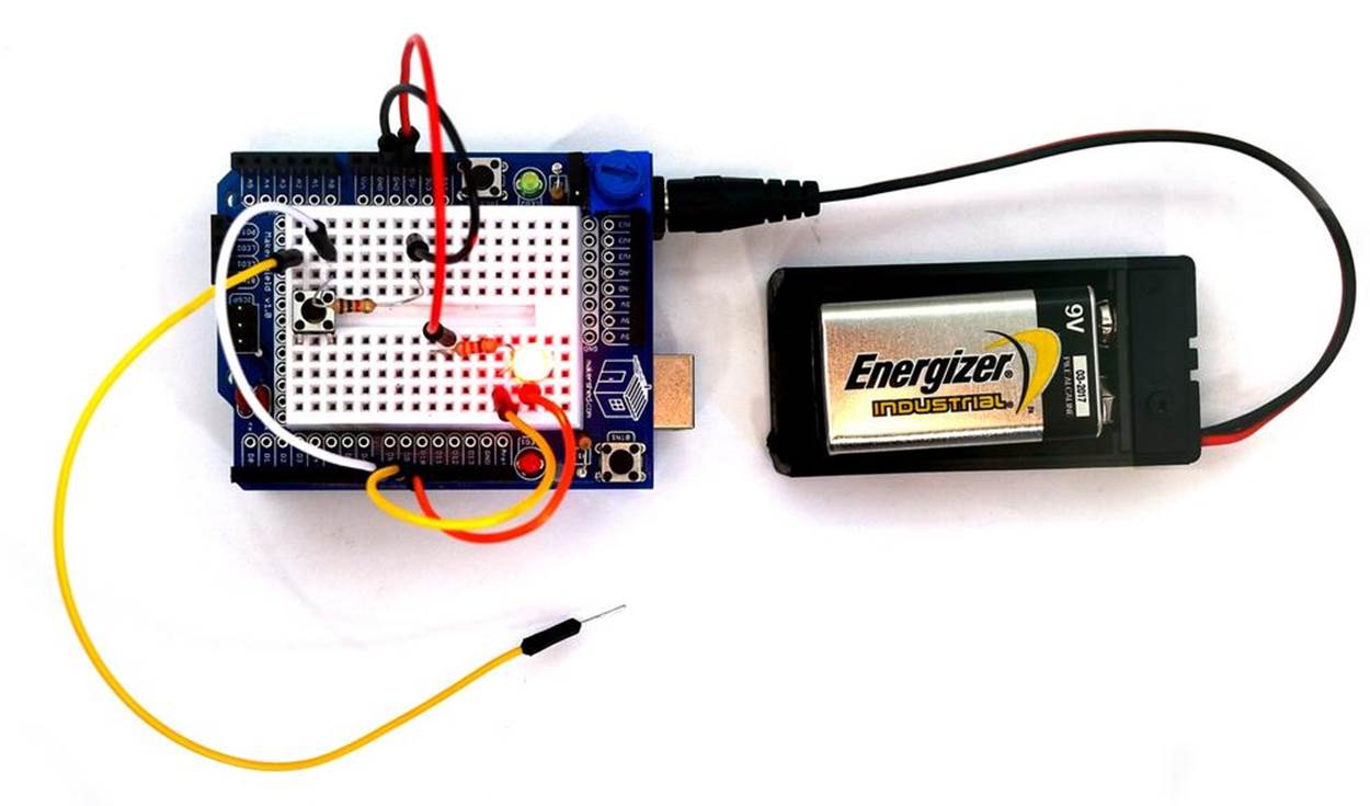
Figure 15-1. A Logic Tester with an RGB LED
Let’s Build a Logic Tester
The Logic Tester is an easy-to-build Arduino microcontroller device. The RGB has three individual color LEDs that allow binary data to be seen visually. The RGB LED pinout is shown in Figure 15-2. Only the red and green LEDs will be used to show the binary logic values of “0” and “1”. To ensure proper operation of the RGB LED, the flat side of the LED should be facing the Test pushbutton switch. See Figure 15-2 for the proper orientation of the RGB LED. Some LEDS may have the blue and green leads swapped. If yours is like that, you may need to move the G wire to the pin labeled B.
TECH NOTE
Base 2 is the number format for binary data.
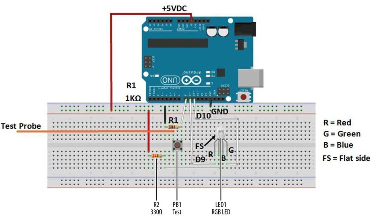
Figure 15-2. Fritzing diagram for a logic tester with an RGB LED
Upload the Logic Tester Sketch
With the Logic Tester built, it’s time to upload the sketch. As shown in Example 15-1, the sketch operates an RGB LED using a pushbutton switch and two fixed resistors. Here are the steps you’ll need to follow:
1. Attach the Arduino to your computer using a USB cable.
2. Open the Arduino software and type Example 15-1 into the software’s text editor.
3. Upload the sketch to the Arduino.
Once the Logic Tester sketch has been uploaded to the Arduino microcontroller, the RGB’s red LED will be on, as shown in Figure 15-1. Attaching the long test wire to the +5VDC source on the MakerShield and pressing the pushbutton switch will allow the RGB green LED to turn on, as shown in Figure 15-3.
Example 15-1. The Logic Tester sketch
/*
Logic Tester with RGB LED
Turns on the green LED when a logic "1" (+5V) signal is detected. The
red LED will turn on at logic "0" (0V) signal. Also, when powering
up the Arduino the red LED is on.
4 May 2013
Don Wilcher
*/
// RG pins wired to the Arduino microcontroller
// give them names:
int redled = 9;
int grnled = 10;
int probein = 8;
int probeStatus = 0;
// the setup routine runs once when you press reset:
void setup() {
// initialize the digital pins as outputs:
pinMode(redled, OUTPUT);
pinMode(grnled, OUTPUT);
pinMode(probein, INPUT);
// turn RGB outputs off:
digitalWrite(redled, HIGH);
digitalWrite(grnled, HIGH);
}
// the loop routine runs over and over again forever:
void loop() {
// read the status of the test probe value:
probeStatus = digitalRead(probein);
if (probeStatus == HIGH) { // check if the test probe value is HIGH
digitalWrite(redled, HIGH); // turn the red LED off (HIGH is off)
digitalWrite(grnled, LOW); // turn the green LED on (LOW is on)
}
else {
digitalWrite(redled, LOW); // turn the red LED on
digitalWrite(grnled, HIGH); // turn the green LED off
}
}
TECH NOTE
HIGH is equivalent to binary 1 and LOW is equivalent to binary 0.
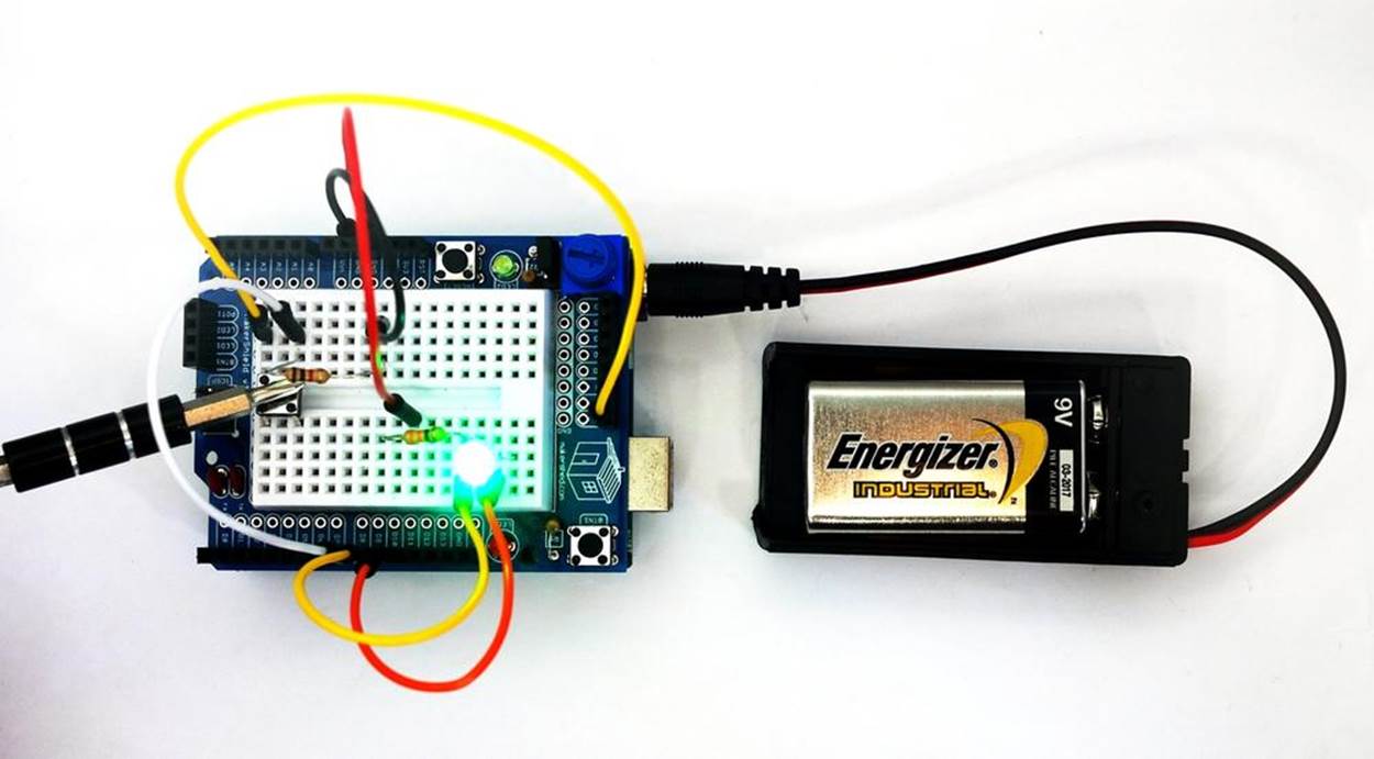
Figure 15-3. The Logic Tester checking +5VDC on MakerShield
Circuit Theory
Pressing the pushbutton will close the switch and allow +5 volts DC electrical current to flow through the test circuit. The Arduino reads digital pin 8 to determine if the pin is receiving +5 volts (i.e., set to HIGH) or if it is not receiving any voltage (i.e., set to LOW). The Arduino takes that information and lights up the appropriate LED: the green LED indicates that the pin is receiving +5 volts, and the red LED indicates 0 voltage. The digital pins used to operate the RGB’s red and green LEDs are D9 and D10.
The block diagram in Figure 15-4 shows the electronic component blocks and the electrical signal flow for the Logic Tester. A Fritzing electronic circuit schematic diagram of the tester is shown in Figure 15-5. Electronic circuit schematic diagrams are used by electrical/electronic engineers to design and build cool electronic products for society.
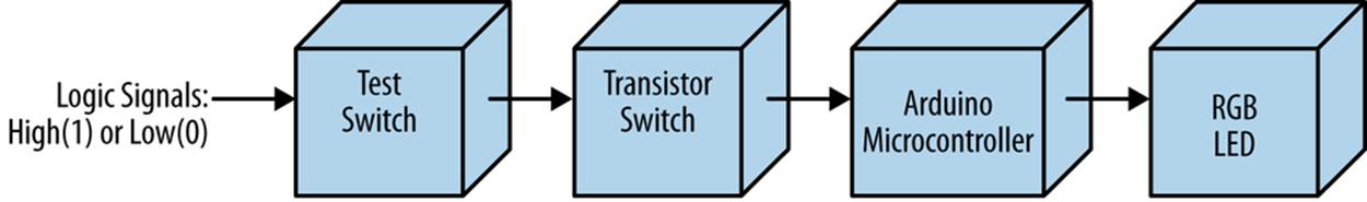
Figure 15-4. The Logic Tester block diagram
TECH NOTE
A block diagram is used to show electrical signal flow of electronic products.
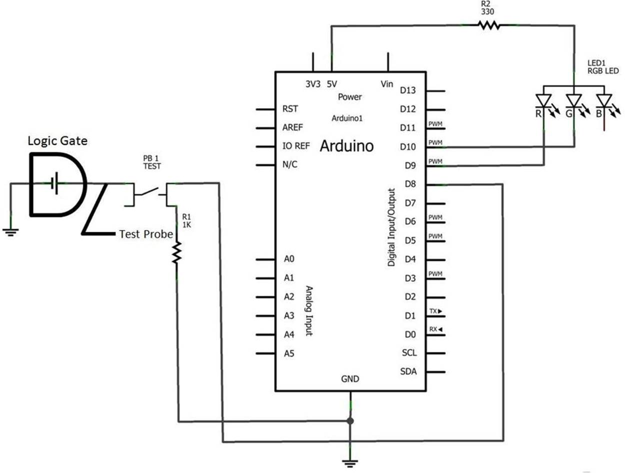
Figure 15-5. The Logic Tester Fritzing circuit schematic diagram
Something to Think About
How can the Logic Tester be operated without a pushbutton switch?
All materials on the site are licensed Creative Commons Attribution-Sharealike 3.0 Unported CC BY-SA 3.0 & GNU Free Documentation License (GFDL)
If you are the copyright holder of any material contained on our site and intend to remove it, please contact our site administrator for approval.
© 2016-2026 All site design rights belong to S.Y.A.