Make: Basic Arduino Projects - 26 Experiments with Microcontrollers and Electronics (2014)
Chapter 16. A Logic Tester (with an LCD)
The Logic Tester project in Chapter 15 allowed you to check the digital data values the Arduino uses to control motors and LEDs. The tester’s two LEDs offer a quick way to see the digital data. In this project, you’ll make an awesome change to the tester by displaying “HIGH (1)” or “LOW (0)” data messages on an LCD. The electronic components to build this device are shown in the Parts List. The Logic Tester with an LCD is shown in Figure 16-1.
Parts List
§ Arduino microcontroller
§ Full breadboard
§ R1: 10KΩ potentiometer
§ R2: 1KΩ resistor (brown, black, red stripes)
§ R3: 330Ω resistor (orange, orange, brown stripes)
§ Q1: S39014 NPN transistor or equivalent
§ PB1: pushbutton switch
§ One long jumper wire
§ LCD1: LMB162ABC 16x2 LCD (liquid crystal display) with soldered 16-pin male header (electrical connector)
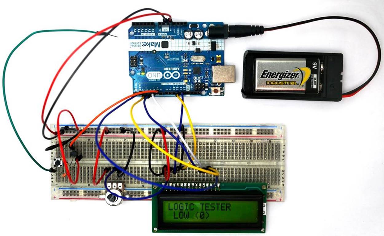
Figure 16-1. A Logic Tester with an LCD
Let’s Build a Logic Tester
Building this tester requires the use of an LCD. If this is your first time using an LCD, I suggest reading Chapter 14. For help adding the 16-pin male header to the LCD, see Figure 14-2 and Figure 14-3. The 10KΩ potentiometer’s center pin is wired to pin number 3 of the LCD. The potentiometer’s remaining pins should be wired to +5VDC and ground. Place the LCD onto the solderless breadboard, as shown in Figure 16-2. LCD pin numbers 1 and 2 are wired to ground and +5VDC, respectively. Adjust the 10KΩ potentiometer contrast control for the LCD for proper pixel-square visibility. For reference on how to do this, see Figure 14-4.
Complete the rest of the tester wiring using the Fritzing diagram shown in Figure 16-2.
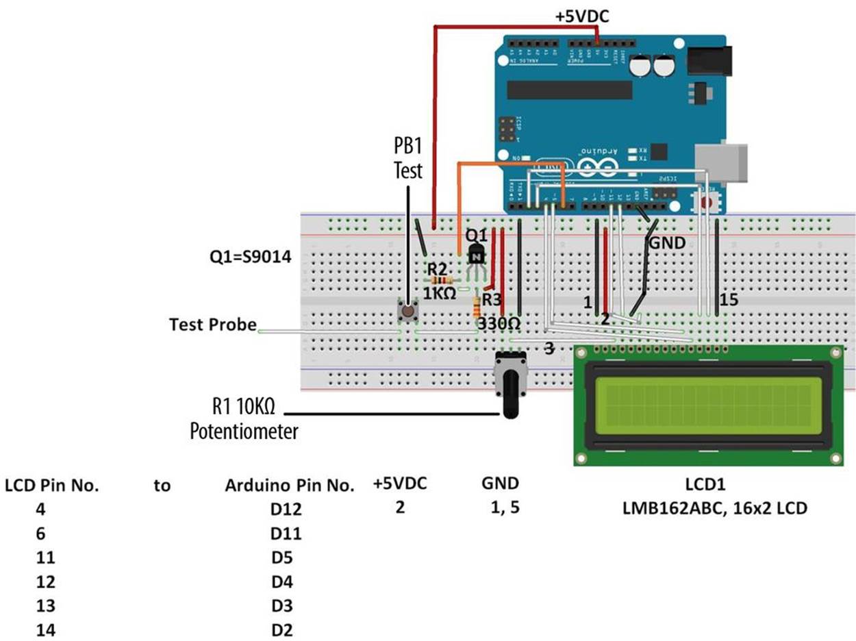
Figure 16-2. Fritzing diagram for a Logic Tester with an LCD
TECH NOTE
Want to learn more about digital logic? Read Experiment 19 in Charles Platt’s Make: Electronics.
Upload the Logic Tester Sketch
With the Logic Tester built, it’s time to upload the sketch. Example 16-1 operates an LCD using a pushbutton switch, a transistor, and two fixed resistors. Here are the steps you’ll need to follow:
1. Attach the Arduino to your computer using a USB cable.
2. Open the Arduino software and type Example 16-1 into the software’s text editor.
3. Upload the sketch to the Arduino.
Once the Logic Tester sketch has been uploaded to the Arduino, the LCD will display a message, as shown in Figure 16-1. Take the long jumper wire (test probe) from the pushbutton switch and attach it to the +5V source of the Arduino (for reference, see Figure 16-2). Press the pushbutton switch and the LCD will display “HIGH (1)” for the +5V source, as shown in Figure 16-3. Impress the local Makerspace by testing Arduino and digital electronic circuits with your Logic Tester!
Example 16-1. The Logic Tester sketch
/*
Logic Tester
LCD displays "HIGH (1)" when digital circuit signal is +5V. A "LOW (0)"
is displayed when digital circuit signal is OV.
27 April 2013
Don Wilcher
*/
// include the LCD library code:
#include <LiquidCrystal.h>
// set up pins on Arduino for LCD and transistor lead:
LiquidCrystal lcd(12,11,5,4,3,2);
int xistorPin = 6;
int digitalStatus = 0; // variable for reading the digital circuit state
// initialize the transistor pin as an input and set up the LCD's number
// of columns and rows:
void setup() {
lcd.begin(16,2);
lcd.setCursor(0,0);
lcd.print("LOGIC TESTER");
pinMode(xistorPin, INPUT);
}
void loop() {
// check if digital signal is HIGH or LOW:
digitalStatus = digitalRead(xistorPin);
if (digitalStatus == HIGH) {
// if digital circuit signal is +5V, display HIGH (1):
lcd.setCursor(0,1);
lcd.print("HIGH (1) "); // display HIGH (1)
}
else {
// if digital circuit signal is 0V, display LOW (0):
lcd.setCursor(0,1);
lcd.print(" LOW (0) ");
}
}
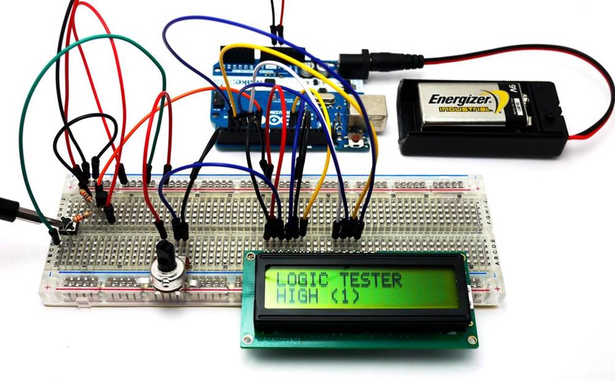
Figure 16-3. The Logic Tester testing the Arduino’s +5V source
TECH NOTE
An electrical tester used to check digital circuits is called a logic probe.
Circuit Theory
Pressing the pushbutton will close the switch and allow +5 volts DC electrical current to flow through the circuit. The Arduino reads digital pin 6 to determine if the pin is receiving +5 volts (i.e., set to HIGH), or if it is not receiving any voltage (i.e., set to LOW). The Arduino takes that information and sends it to the LCD display via digital pins D2, D3, D4, D5, D11, and D12. The LCD then displays “HIGH (1)” or “LOW (0)” depending on the state of digital pin 6.
The block diagram in Figure 16-4 shows the electronic component blocks and the electrical signal flow for the Logic Tester. A Fritzing electronic circuit schematic diagram of the tester is shown in Figure 16-5. Electronic circuit schematic diagrams are used by electrical/electronic engineers to design and build cool electronic products for society.
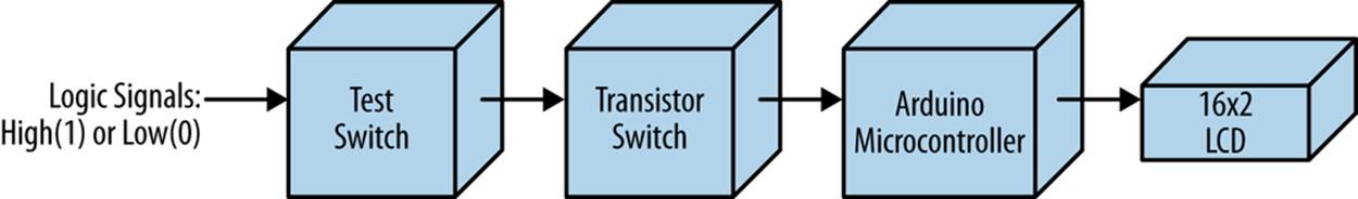
Figure 16-4. The Logic Tester block diagram
TECH NOTE
The initial LCD message displayed before testing a digital circuit is “LOW(0).”
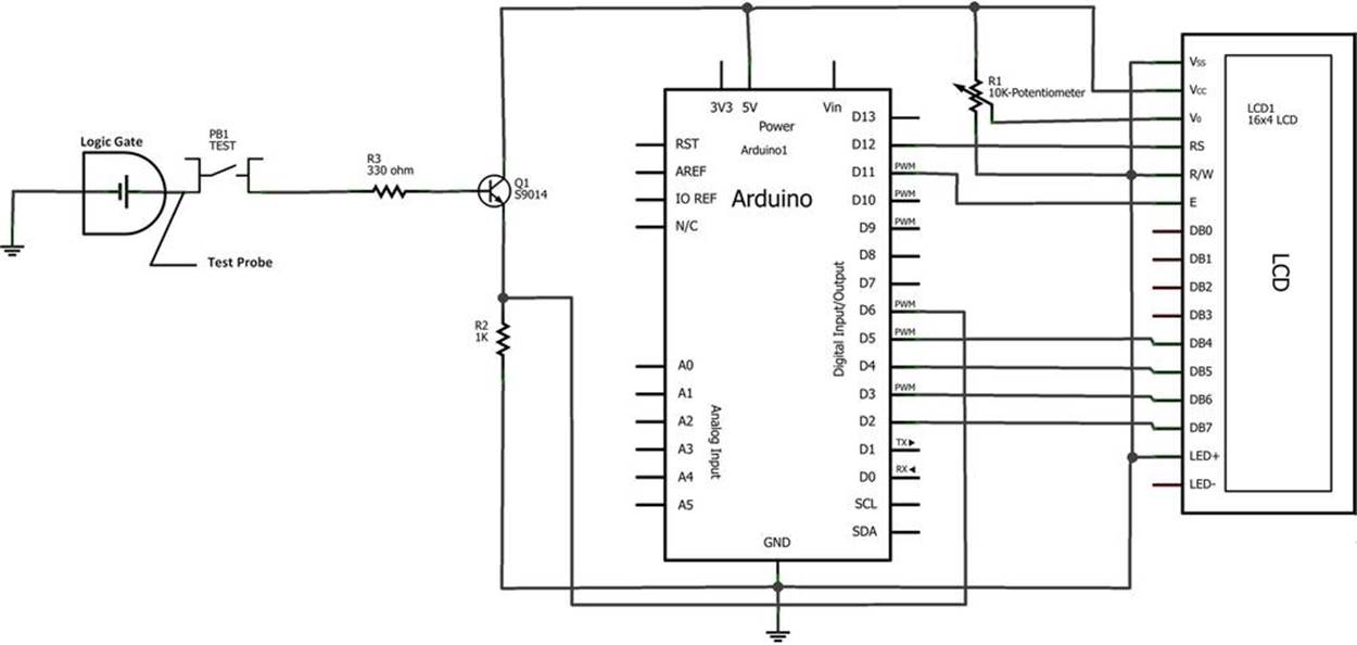
Figure 16-5. The Logic Tester Fritzing circuit schematic diagram
Something to Think About
How can a small piezo buzzer be used with the Logic Tester?
All materials on the site are licensed Creative Commons Attribution-Sharealike 3.0 Unported CC BY-SA 3.0 & GNU Free Documentation License (GFDL)
If you are the copyright holder of any material contained on our site and intend to remove it, please contact our site administrator for approval.
© 2016-2026 All site design rights belong to S.Y.A.