Make: Basic Arduino Projects - 26 Experiments with Microcontrollers and Electronics (2014)
Chapter 17. The Amazing Pushbutton (with Processing)
With this project, you can make colorful lines and numbers move up and down your computer screen as you press a simple pushbutton switch. To do that, this project will introduce you to Processing, a simple, easy-to-learn programming language (very much like the Arduino language) that makes it very easy to display graphics on a computer screen. When you connect an Arduino to Processing, you can make your Arduino draw on a screen!
The electronic components to build this device are shown in the Parts List. The Amazing Pushbutton is shown in Figure 17-1.
Parts List
§ Arduino microcontroller
§ MakerShield kit
§ R1: 1KΩ resistor (brown, black, red stripes)
§ PB1: pushbutton switch
§ USB cable
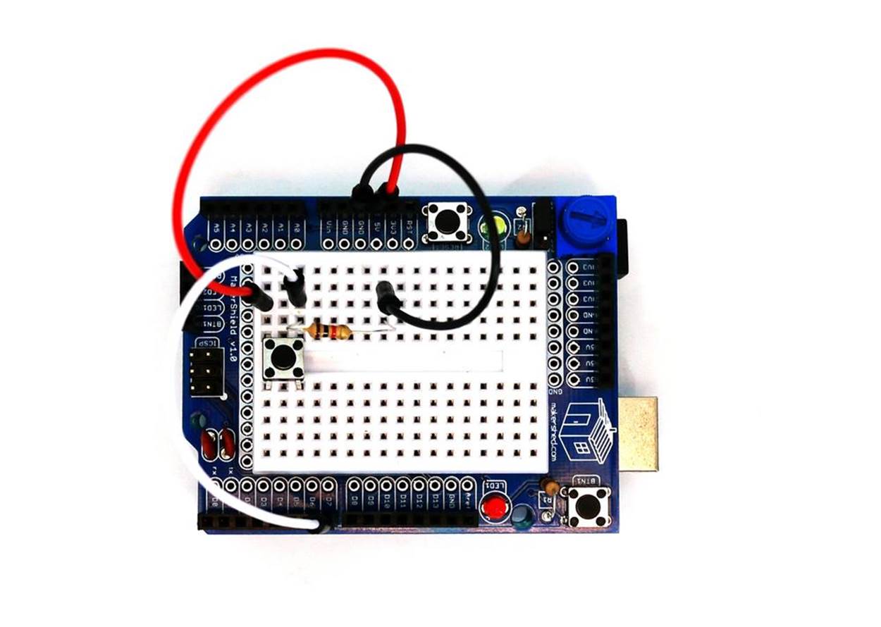
Figure 17-1. The Amazing Pushbutton
Let’s Build an Amazing Pushbutton
Building the Amazing Pushbutton requires the use of a USB cable to send digital information from the Arduino to a computer screen. As shown in Figure 17-1, the device is quite simple to build, using only a 1KΩ fixed resistor and a pushbutton switch. The two components are connected in series. Where the two electronic components tie together, a jumper wire connects between them and pin D7 of the Arduino microcontroller.
Complete the rest of the Amazing Pushbutton wiring using the Fritzing diagram shown in Figure 17-2. The placement of the parts is not critical, so experiment with the locations of the electronic components and electrical wiring of the device. Although a mini breadboard is shown in the Fritzing diagram, the MakerShield protoboard provides a compact way to wire the device.
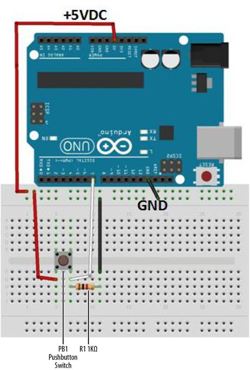
Figure 17-2. The Amazing Pushbutton Fritzing diagram
TECH NOTE
The clicking sound made when pressing the pushbutton switch provides audible feedback of closing electrical contacts.
Upload the Amazing Pushbutton Sketch
With the Amazing Pushbutton built, it’s time to upload the sketch. Example 17-1 sends digital information to the Arduino IDE (integrated development environment) Serial Monitor and turns the onboard LED on and off with each press of the pushbutton switch. Here are the steps you’ll need to follow:
1. Attach the Arduino to your computer using a USB cable.
2. Open the Arduino software and type Example 17-1 into the software’s text editor.
3. Upload the sketch to the Arduino.
Example 17-1. The Amazing Pushbutton sketch
/*
* The Amazing Pushbutton
*
* Reads a digital input from a pushbutton switch and sends the letter
* L or H to the Serial Monitor.
*
*
*/
// variables for input pin and control LED
int digitalInput = 7;
int LEDpin = 13;
// variable to store the value
int value = 0;
void setup(){
// declaration pin modes
pinMode(digitalInput, INPUT);
pinMode(LEDpin, OUTPUT);
// begin sending over serial port
Serial.begin(9600);
}
void loop(){
// read the value on digital input
value = digitalRead(digitalInput);
// write this value to the control LED pin
digitalWrite(LEDpin, value);
// if value is high then send the letter 'H'; otherwise, send 'L' for low
if (value) Serial.print('H');
else
Serial.print('L');
// wait a bit to not overload the port
delay(10);
}
Once the Amazing Pushbutton sketch has been uploaded to the Arduino, the Serial Monitor will display “L” repeatedly in a row, as shown in Figure 17-3. Press the pushbutton switch, and the Serial Monitor displays “H” repeatedly in a row (see Figure 17-4).
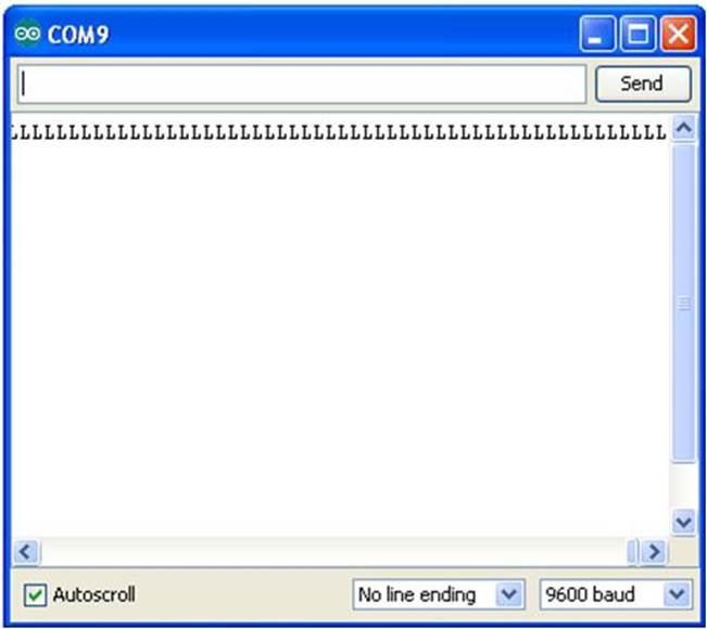
Figure 17-3. L’s being displayed on the Arduino Serial Monitor
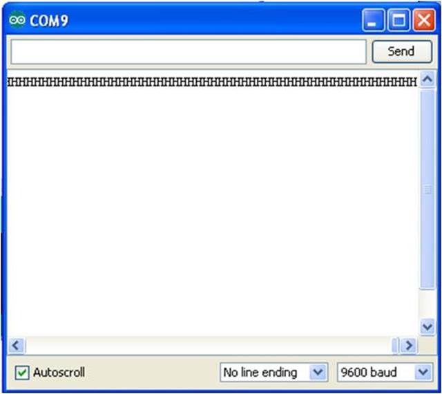
Figure 17-4. H’s being displayed on the Arduino Serial Monitor
Download and Install Processing Notes
Before building this awesome visual Arduino Microcontroller project, you have to install the Processing programming language on your computer. Here are the installation instructions:
1. Go to the Processing download web page.
2. Select the software that meets your operating system’s requirements.
3. Once the Processing software has been downloaded to your hard drive, follow the prompts to complete the installation process.
After installing the Processing programming language onto your computer, you’re now ready to build the visualization software for the Amazing Pushbutton device!
Let’s Visualize Digital Data with Processing
The characters “L” and “H” are an interesting way to represent the information you get when the pushbutton turns on and off. But if we really want to see the “magic” of the pushbutton, we’ll need to use a graphical software language called Processing. Processing software allows digital information (actually, just about any kind of information) to be changed into computer graphics quite easily.
With the Arduino attached to your computer, the state of the pushbutton, represented by L’s and H’s, can be changed to a colorful scale, showing increasing and decreasing numbers. The pa_Pushbutton Processing sketch displays an interactive scale on your computer screen, as shown inFigure 17-5.
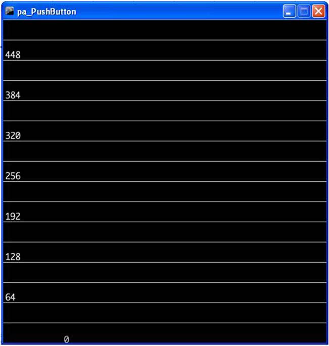
Figure 17-5. We start with a very simple background scale created in Processing
TECH NOTE
Watch the online PBS Off Book episode titled “The Art of Data Visualization”.
Example 17-2 shows the pa_Pushbutton Processing sketch for the Amazing Pushbutton.
Example 17-2. The pa_Pushbutton Processing sketch
/*
* pa_PushButton
*
* Reads the values which represent the state of a pushbutton
* from the serial port and draws increasing/decreasing horizontal lines.
*
*
*/
// importing the processing serial class
import processing.serial.*;
// the display item draws background and grid
DisplayItems di;
// definition of window size and framerate
int xWidth = 512;
int yHeight = 512;
int fr = 24;
// attributes of the display
boolean bck = true;
boolean grid = true;
boolean g_vert = false;
boolean g_horiz = true;
boolean g_values = true;
boolean output = false;
// variables for serial connection, portname, and baudrate have to be set
Serial port;
int baudrate = 9600;
int value = 0;
// variables to draw graphics
int actVal = 0;
int num = 6;
float valBuf[] = new float[num];
int i;
// lets user control DisplayItems properties and value output in console
void keyPressed(){
if (key == 'b' || key == 'B') bck=!bck; // background black/white
if (key == 'g' || key == 'G') grid=!grid; // grid on/off
if (key == 'v' || key == 'V') g_values=!g_values; // grid values on/off
if (key == 'o' || key == 'O') output=!output; // turns value output on/off
}
void setup(){
// set size and framerate
size(xWidth, yHeight); frameRate(fr);
// establish serial port connection
// The "2" corresponds to the 3rd port (counting from 0) on the Serial
// Port list dropdown. You might need to change the 2 to something else.
String portname =Serial.list()[2];
port = new Serial(this, portname, baudrate);
println(port);
// create DisplayItems object
di = new DisplayItems();
// clear value buffer
for(i=0; i < num; i++) {
valBuf[0] = 0;
}
}
void drawPushButtonState(){
// read through the value buffer
// and shift the values to the left
for(i=1; i < num; i++) {
valBuf[i-1] = valBuf[i];
}
// add new values to the end of the array
valBuf[num-1] = actVal;
noStroke();
// reads through the value buffer and draws lines
for(int i=0; i < num; i=i+2) {
fill(int((valBuf[i]*255)/height), int((valBuf[i]*255)/height) , 255);
rect(0, height-valBuf[i], width, 3);
fill(int((valBuf[i+1]*255)/height), 255, 0 );
rect(0, height-valBuf[i+1], width, 3);
}
// display value
fill(((bck) ? 185 : 75));
text( ""+(actVal), 96, height-actVal);
}
void serialEvent(int serial){
// if serial event is 'H' actVal is increased
if(serial=='H') {
actVal = (actVal < height - (height/16)) ?
(actVal + int(actVal/(height/2))+1) :
(actVal = height - (height/(height/2)));
if (output)
println("Value read from serial port is 'H' - actualValue is now "
+ actVal);
} else {
// if serial event is 'L' actVal is decreased
actVal = (actVal > 1) ?
(actVal = actVal - int(actVal/64)-1) :
(actVal=0);
if (output)
println("Value read from serial port is 'L' - actualValue is now "
+ actVal);
}
}
void draw(){
// listen to serial port and trigger serial event
while(port.available() > 0){
value = port.read();
serialEvent(value);
}
// draw background, then PushButtonState and
// finally rest of DisplayItems
di.drawBack();
drawPushButtonState();
di.drawItems();
}
Next, we need to use the DisplayItems sketch to display the interactions with the Arduino on your screen. To do this, you need to open a new tab in the Processing IDE for the DisplayItems sketch. Enter Example 17-3 into the new tab in the Processing IDE text editor.
Example 17-3. The DisplayItems Processing sketch
/*
* DisplayItems
*
* This class draws background color, grid and value scale
* according to the boolean variables in the pa_file.
*
* This file is part of the Arduino meets Processing Project.
* For more information visit http://www.arduino.cc.
*
* created 2005 by Melvin Ochsmann for Malmo University
*
*/
class DisplayItems{
// variables of DisplayItems object
PFont font;
int gridsize;
int fontsize = 10;
String fontname = "Monaco-14.vlw";
String empty="";
int i;
// constructor sets font and fontsize
DisplayItems(){
font = loadFont(fontname);
gridsize = (width/2)/16+(height/2)/16;
if(gridsize > 20) fontsize = 14;
if(gridsize > 48) fontsize = 22;
textFont(font, fontsize);
}
// draws background
void drawBack(){
background( (bck) ? (0) : (255) );
}
// draws grid and value scale
void drawItems(){
if(grid){ stroke( (bck) ? (200) : (64) );
fill((bck) ? (232) : (32) );
// vertical lines
if(g_vert){
for (i=0; i < width; i+=gridsize){
line(i, 0, i, height);
textAlign(LEFT);
if (g_values &&
i%(2*gridsize)==0 &&
i < (width-(width/10)))
text( empty+i, (i+fontsize/4), 0+fontsize);
}}
// horizontal lines
if(g_horiz){
for (int i=0; i < height; i+=gridsize){
line(0, i, width, i);
textAlign(LEFT);
if (g_values &&
i%(2*gridsize)==0)
text( empty+(height-i), 0+(fontsize/4), i-(fontsize/4));
}}
}
}
}// end class DisplayItems
After typing the sketch, click the play button to obtain the image shown in Figure 17-5. Press the Arduino’s pushbutton to watch the numbers increase and the color bar (horizontal lines) move up the scale, as shown in Figure 17-6.
THE AMAZING PUSHBUTTON EASTER EGGS!
In addition to creating colorful lines and changing numbers, you can change the look of the scale using the following keys:
§ b/B: toggles background black/white
§ g/G: toggles grid on/off
§ v/V: toggles grid values on/off
§ o/O: turns value output on/off
See if you can find additional eggs hidden in the Processing sketch. Happy Hacking!
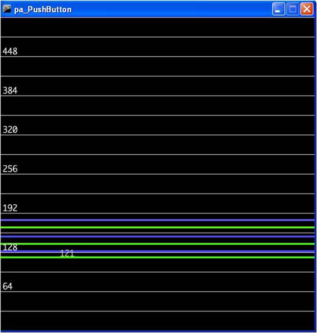
Figure 17-6. The Amazing Pushbutton in action
TECH NOTE
For additional information about processing, see Casey Reas and Ben Fry’s Getting Started with Processing (Maker Media, 2010).
The block diagram in Figure 17-7 shows the electronic component blocks and the data flow for the Amazing Pushbutton. A Fritzing electronic circuit schematic diagram of the Amazing Pushbutton is shown in Figure 17-8.
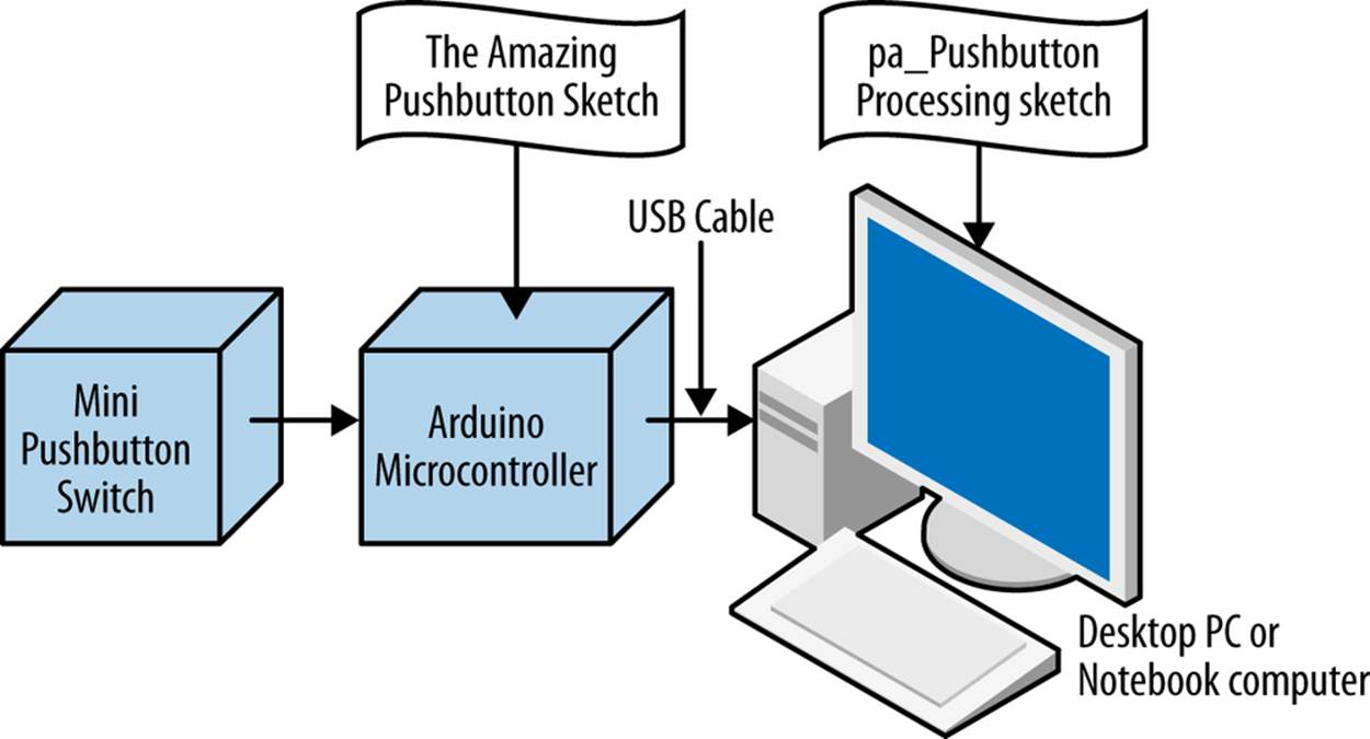
Figure 17-7. The Amazing Pushbutton block diagram
Troubleshooting Tips for Processing
As in all Maker projects, a bug can occasionally creep in. Processing is an awesome software package for developing cool Arduino microcontroller projects, but it can be challenging to use. Here are a few troubleshooting tips for the most common problems that can occur:
§ Make sure the Arduino microcontroller is communicating with the Processing software through USB connection. If the Arduino is not attached to the Processing software, it may cause communication errors.
§ Make sure the Amazing Pushbutton sketch is running on Arduino before starting the Processing sketch. If the Processing software is unable to obtain data from the Arduino microcontroller (because it wasn’t running), it will generate an “unrecognized device error.”
§ Make sure text for both the Arduino and Processing sketches is typed correctly as shown in the software listings. Most of the software bugs are caused by syntax or incorrectly typed code for both programming languages.
Following these three guidelines should minimize your frustration when it comes to debugging the Amazing Pushbutton device project build.
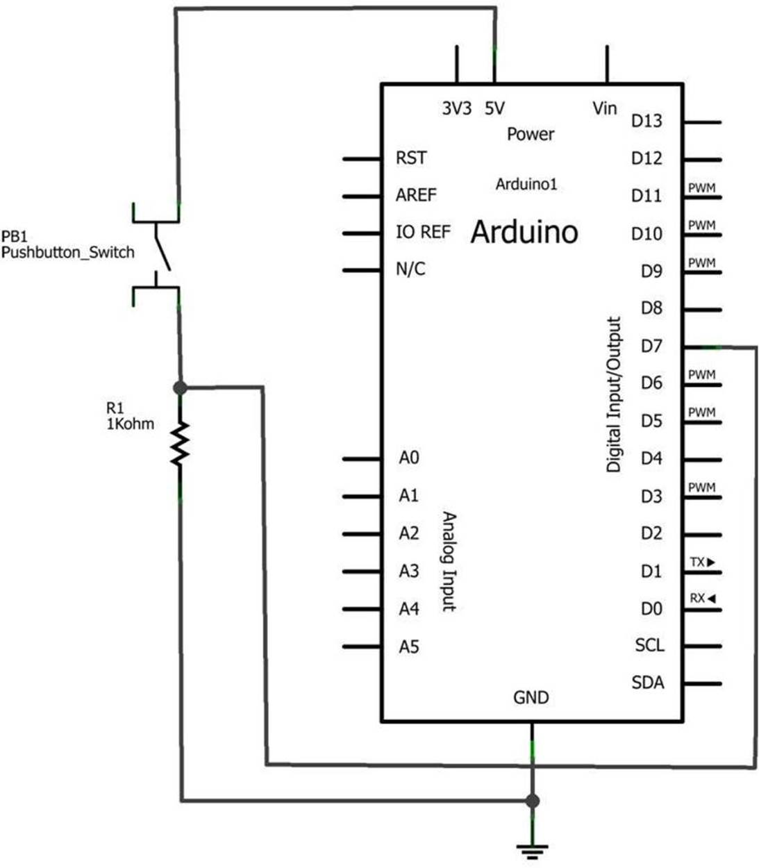
Figure 17-8. The Amazing Pushbutton Fritzing circuit schematic diagram
Something to Think About
How can the letters “L” and “H” in Figure 17-3 and Figure 17-4 be replaced with the numbers “0” and “1”?
All materials on the site are licensed Creative Commons Attribution-Sharealike 3.0 Unported CC BY-SA 3.0 & GNU Free Documentation License (GFDL)
If you are the copyright holder of any material contained on our site and intend to remove it, please contact our site administrator for approval.
© 2016-2026 All site design rights belong to S.Y.A.