Make: Basic Arduino Projects - 26 Experiments with Microcontrollers and Electronics (2014)
Chapter 18. The Terrific Tilt Switch (with Processing)
Processing is an awesome programming language that creates graphics and pictures that you can move in fun ways across the computer screen. Do you remember the tilt switch from Chapter 3? It was an electrical device capable of controlling electronic devices, based on its orientation or position. If you combine the Processing language with a tilt switch, you can create computer graphics that move across the screen when you make simple body gestures like waving a hand or raising and lowering an arm! In this project, a white circle will move from side to side on your computer screen as you rotate the tilt switch.
The electronic components to build this device are shown in the Parts List. The Terrific Tilt Switch is shown in Figure 18-1.
Parts List
§ Arduino microcontroller
§ MakerShield kit
§ R1: 1KΩ resistor (brown, black, red stripes)
§ S1: tilt switch
§ USB cable
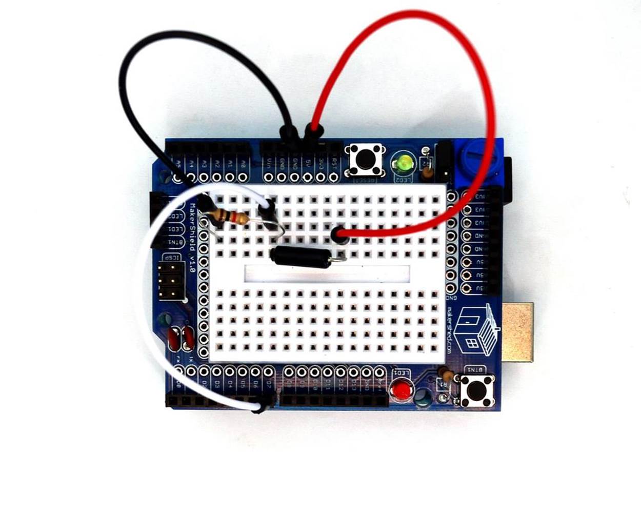
Figure 18-1. The Terrific Tilt Switch
Let’s Build a Terrific Tilt Switch
The Terrific Tilt Switch, like the Amazing Pushbutton, requires a USB cable to send digital information from the switch to the computer screen. As shown in Figure 18-1, the device is quite simple to build: it requires just a 1KΩ fixed resistor and a tilt switch. The two components are connected in series like the Amazing Pushbutton device. Where the two components tie together, a jumper wire connects between them and pin D7 of the Arduino microcontroller.
The Terrific Tilt Switch can be built using the Fritzing wiring diagram shown in Figure 18-2. The placement of the parts is not critical, so have some fun placing the components in different places. Although the Fritzing diagram shows a mini breadboard, feel free to use the MakerShield protoboard if you want.
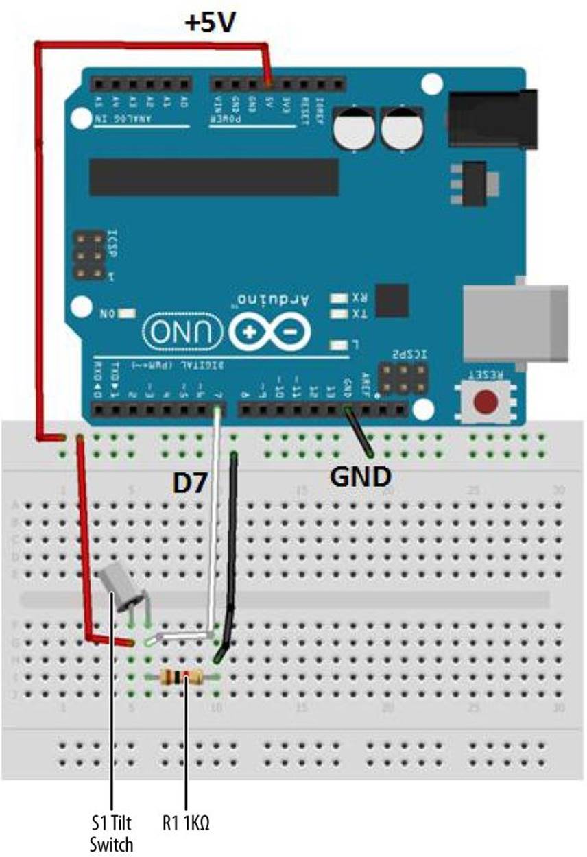
Figure 18-2. The Terrific Tilt Switch Fritzing wiring diagram
Upload the Terrific Tilt Switch Sketch
It’s time to upload the Arduino sketch for the Terrific Tilt Switch. Example 18-1 takes information from the tilt switch and sends it to the Arduino IDE (integrated development environment) Serial Monitor, displaying a series of the characters “H” and “L” with each rotation of the tilt switch.
Did you notice that parts of the program look like the listing shown in Chapter 17? That’s because the serial communication technique—the part of the code that lets the Arduino talk with Processing—remains the same no matter what the Arduino is using as input or how Processing displays the data. Here are the steps you’ll need to follow:
1. Attach the Arduino to your computer using a USB cable.
2. Open the Arduino software and type Example 18-1 into the software’s text editor.
3. Upload the sketch to the Arduino.
Once the Terrific Tilt Switch sketch has been uploaded to the Arduino, the Serial Monitor will display “L” repeatedly in a row, as shown in Figure 18-3. If you tilt the switch, the Serial Monitor will display “H” repeatedly (see Figure 18-4).
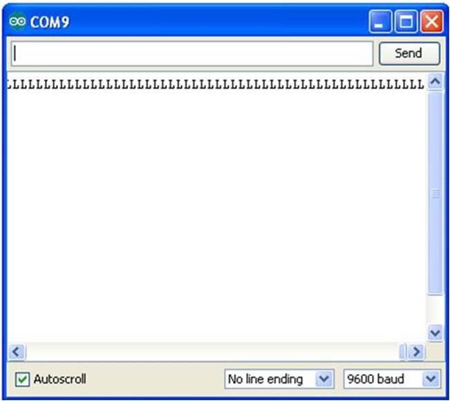
Figure 18-3. L’s being displayed on the Arduino Serial Monitor
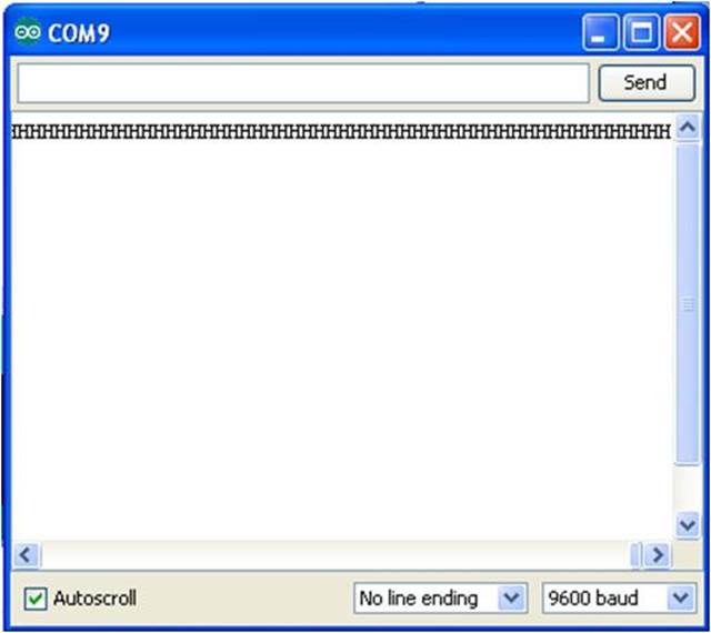
Figure 18-4. H’s being displayed on the Arduino Serial Monitor
Example 18-1. The Terrific Tilt Switch sketch
/*
* The Terrific Tilt Switch
*
* Reads a digital input from a tilt switch and sends a series of
* L's or H's to the Serial Monitor.
*
*
*/
// variables for input pin and control LED
int digitalInput = 7;
int LEDpin = 13;
// variable to store the value
int value = 0;
void setup(){
// declaration pin modes
pinMode(digitalInput, INPUT);
pinMode(LEDpin, OUTPUT);
// begin sending over serial port
Serial.begin(9600);
}
void loop(){
// read the value on digital input
value = digitalRead(digitalInput);
// write this value to the control LED pin
digitalWrite(LEDpin, value);
// if value is high then send the letter 'H'; otherwise, send 'L' for low
if (value) Serial.print('H');
else
Serial.print('L');
// wait a bit to not overload the port
delay(10);
}
Let’s Visualize Digital Data with Processing
With the Arduino attached to a Processing sketch running on your computer, the digital information (L’s and H’s) from the Arduino can be changed to a horizontally moving white circle based on the orientation of the tilt switch, as shown in Figure 18-5 and Example 18-2.
TECH NOTE
Check out the Processing sketch listings for Arduino projects.
Example 18-2. The pa_Tilt Processing sketch
/*
* pa_Tilt
*
* Reads the values which represent the state of a Tilt switch
* from the serial port and draws white-filled circle with vertical lines.
* created 2005 by Melvin Ochsmann for Malmo University
*
*/
import processing.serial.*;
DisplayItems di;
int xWidth = 512;
int yHeight = 512;
int fr = 24;
boolean bck = true;
boolean grid = true;
boolean g_vert = true;
boolean g_horiz = false;
boolean g_values = false;
boolean output = true;
Serial port;
// The "2" corresponds to the 3rd port (counting from 0) on the Serial
// Port list dropdown. You might need to change the 2 to something else.
String portname = Serial.list()[2];
int baudrate = 9600;
int value = 0;
boolean tilted = true;
float a = 0;
int speed = 5; // how many pixels that the circle will move per frame
void keyPressed(){
if (key == 'b' || key == 'B') bck=!bck;
if (key == 'g' || key == 'G') grid=!grid;
if (key == 'v' || key == 'V') g_values=!g_values;
if (key == 'o' || key == 'O') output=!output;
}
void setup(){
size(xWidth, yHeight);
frameRate(fr);
di = new DisplayItems();
port = new Serial(this, portname, baudrate);
println(port);
}
// Method moves the circle from one side to another,
// keeping within the frame
void moveCircle(){
if(tilted) {
background(0);
a = a + speed;
if (a > (width-50)) {
a = (width-50);
}
ellipse(a, (width/2), 100,100);
}else{
background(0);
a = a - speed;
if (a < 50) {
a = 50;
}
ellipse(a, (width/2), 100,100);
}
}
void serialEvent(int serial){
if(serial=='H') {
tilted = true;
if(output) println("High");
}else {
tilted = false;
if(output) println("Low");
}
}
void draw(){
while(port.available() > 0){
value = port.read();
serialEvent(value);
}
di.drawBack();
moveCircle();
di.drawItems();
}
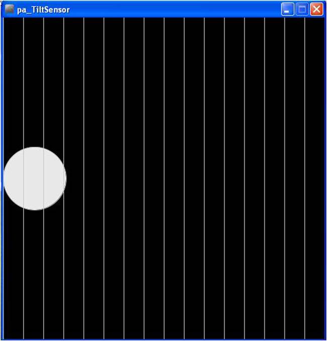
Figure 18-5. An interactive (moving) white-filled circle created in Processing
TECH NOTE
There are a couple of Easter eggs embedded in the pa_Tilt Processing sketch that will allow you to change the appearance of the display. Good Hunting!
Next, open a new tab in the Processing IDE and add Example 18-3 . After typing the sketch, click the play button. Your computer screen should show something very similar to the image shown in Figure 18-5. Rotate the tilt switch and watch the white circle move across your computerscreen, as shown in Figure 18-6.
Example 18-3. The DisplayItems Processing sketch
/*
* DisplayItems
*
* This class draws background color, grid and value scale
* according to the boolean variables in the pa_file.
*
* This file is part of the Arduino meets Processing Project.
* For more information visit http://www.arduino.cc.
*
* created 2005 by Melvin Ochsmann for Malmo University
*
*/
class DisplayItems{
// variables of DisplayItems object
PFont font;
int gridsize;
int fontsize = 10;
String fontname = "Monaco-14.vlw";
String empty="";
int i;
// constructor sets font and fontsize
DisplayItems(){
font = loadFont(fontname);
gridsize = (width/2)/16+(height/2)/16;
if(gridsize > 20) fontsize = 14;
if(gridsize > 48) fontsize = 22;
textFont(font, fontsize);
}
// draws background
void drawBack(){
background( (bck) ? (0) : (255) );
}
// draws grid and value scale
void drawItems(){
if(grid){ stroke( (bck) ? (200) : (64) );
fill((bck) ? (232) : (32) );
// vertical lines
if(g_vert){
for (i=0; i < width; i+=gridsize){
line(i, 0, i, height);
textAlign(LEFT);
if (g_values &&
i%(2*gridsize)==0 &&
i < (width-(width/10)))
text( empty+i, (i+fontsize/4), 0+fontsize);
}}
// horizontal lines
if(g_horiz){
for (int i=0; i < height; i+=gridsize){
line(0, i, width, i);
textAlign(LEFT);
if (g_values &&
i%(2*gridsize)==0)
text( empty+(height-i), 0+(fontsize/4), i-(fontsize/4));
}}
}
}
}// end class Display
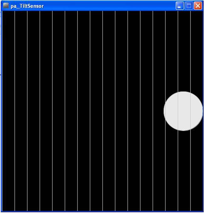
Figure 18-6. The Terrific Tilt Switch in action: the white circle has moved to the right side of the screen
TECH NOTE
A class defines the look and operation of software objects.
The block diagram in Figure 18-7 shows the electronic component blocks and the data flow for the Terrific Tilt Switch. A Fritzing electronic circuit schematic diagram of the Terrific Tilt Switch is shown in Figure 18-8.
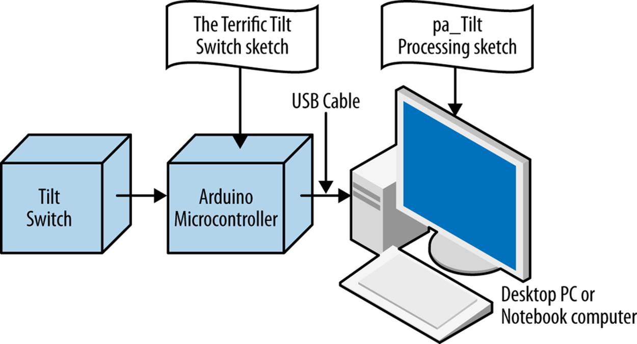
Figure 18-7. The Terrific Tilt Switch block diagram
Something to Think About
How can an external LED be wired to the MakerShield protoboard to visually represent the state of the tilt switch (just like the letters “L” and “H” do in the Serial Monitor)?
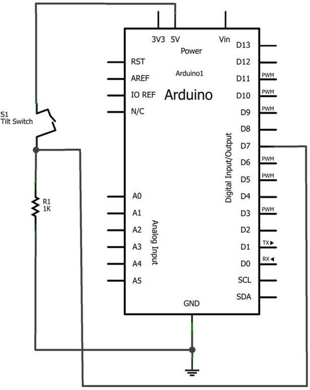
Figure 18-8. The Terrific Tilt Switch Fritzing circuit schematic diagram
All materials on the site are licensed Creative Commons Attribution-Sharealike 3.0 Unported CC BY-SA 3.0 & GNU Free Documentation License (GFDL)
If you are the copyright holder of any material contained on our site and intend to remove it, please contact our site administrator for approval.
© 2016-2026 All site design rights belong to S.Y.A.