Make: Basic Arduino Projects - 26 Experiments with Microcontrollers and Electronics (2014)
Chapter 19. The Rocket Launching Game (with Processing)
Would you like to build a rocket launching game using electronic components from the Ultimate Microcontroller Pack? How cool would it be to launch the rockets from your Maker bench or bedroom? Since launching real rockets is a bit beyond the scope of this book, we’re going to use four pushbutton switches and the Arduino microcontroller to build a virtual rocket launcher. The rest is done in Processing. The electronic components to build this gadget are shown in the Parts List. The Rocket Launcher is shown in Figure 19-1.
Parts List
§ Arduino microcontroller
§ MakerShield kit
§ R1-R5: 1KΩ resistors (brown, black, red stripes)
§ S1-S4: pushbutton switches
§ USB cable
§ Full-size breadboard
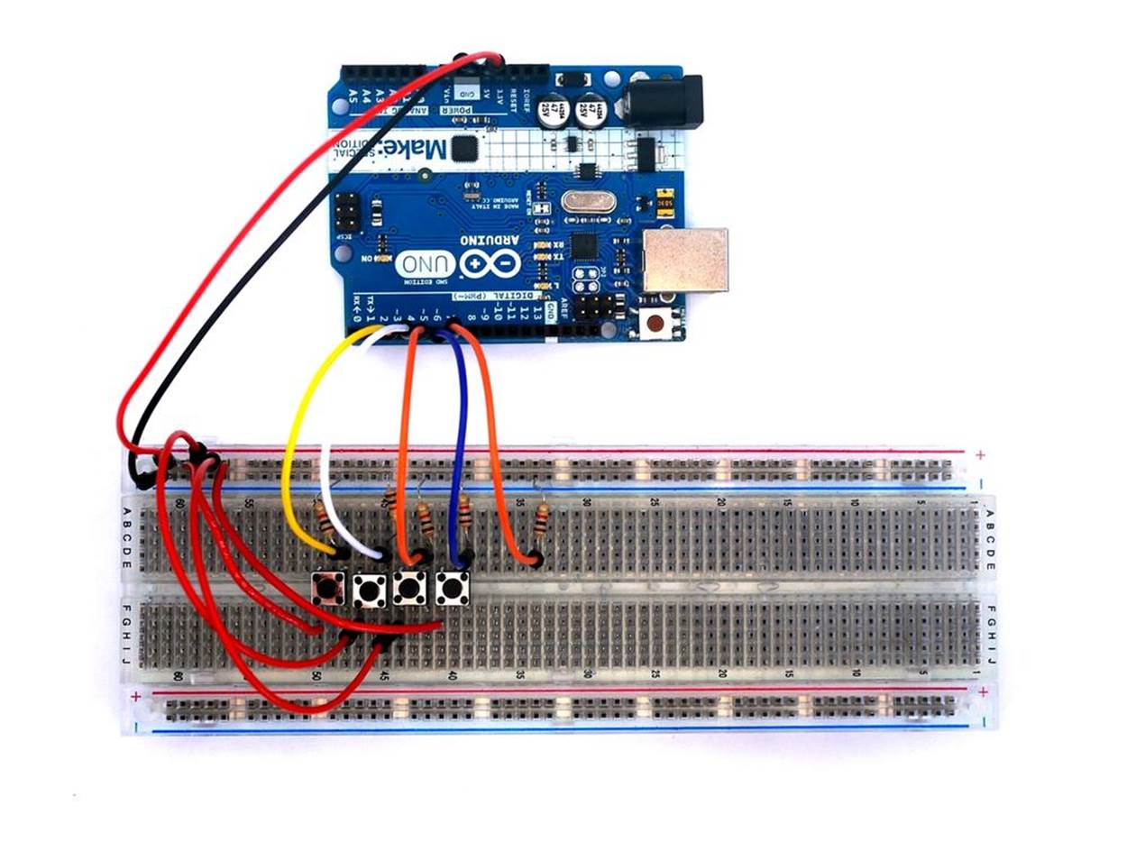
Figure 19-1. The Rocket Launcher
Let’s Build a Rocket Game
The Rocket Game, like the projects in Chapter 17 and Chapter 18, requires the use of a USB cable to send digital information from four pushbutton switches to the computer screen. As shown in Figure 19-1, the breadboard circuit is quite simple to build and requires five 1KΩ fixed resistors and four pushbutton switches.
The basic digital circuit consists of a pushbutton switch and resistor wired in series. This wiring connection is repeated three times for the remaining switches. These switches are connected to pins D3 through D7 of the Arduino microcontroller.
The Rocket Game can be built using the Fritzing wiring diagram shown in Figure 19-2. The placement of the parts is not critical, so experiment with the location of the various electronic components, and the overall wiring of the device. One challenge is to wire all of the electronic components using the awesome (but kind of small) MakerShield protoboard. Can you fit it all on there?
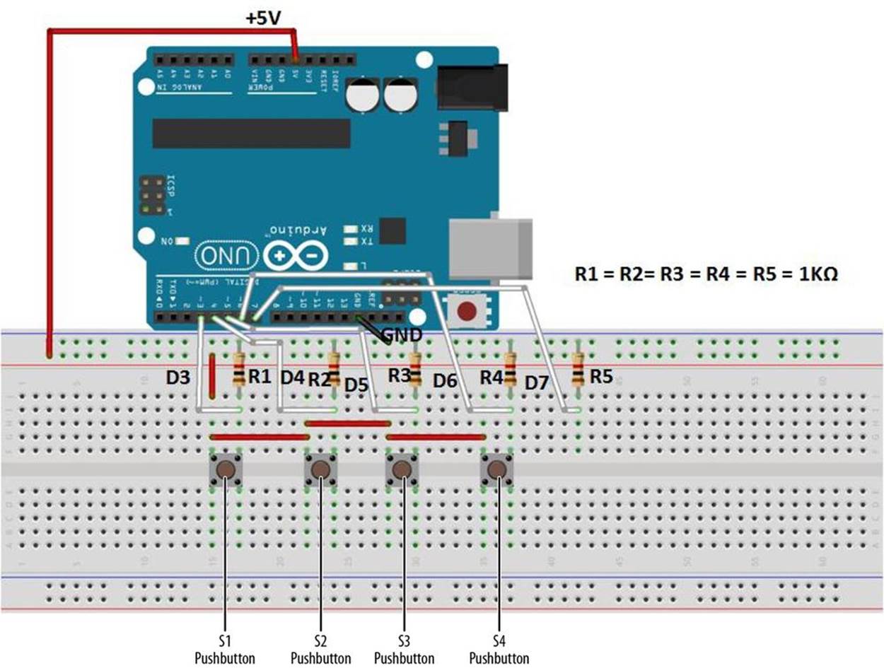
Figure 19-2. The Rocket Launcher Fritzing wiring diagram
TECH NOTE
Processing language version 2.0 is available for download.
Upload the MultiDigital4 Sketch
After building the Rocket Game pushbutton circuit and checking for wiring errors, it is time to upload the sketch. Example 19-1 sends digital information to the Arduino IDE (integrated development environment) Serial Monitor, displaying the numbers 0, 1, 2, and 4 with each individual press of the four pushbutton switches. The serial communication technique used in Chapter 17 and Chapter 18 remains the same for the Arduino software to talk with the Processing programming language. Here are the steps you’ll need to follow:
1. Attach the Arduino to your computer using a USB cable.
2. Open the Arduino software and type Example 19-1 into the software’s text editor.
3. Upload the sketch to the Arduino.
The Serial Monitor will start to display numbers, as shown in Figure 19-3, each time you press the pushbutton. Pushing various combinations of switches will show new results. This information will be displayed in Processing, and will create an awesome visual of rockets being launched on the screen.
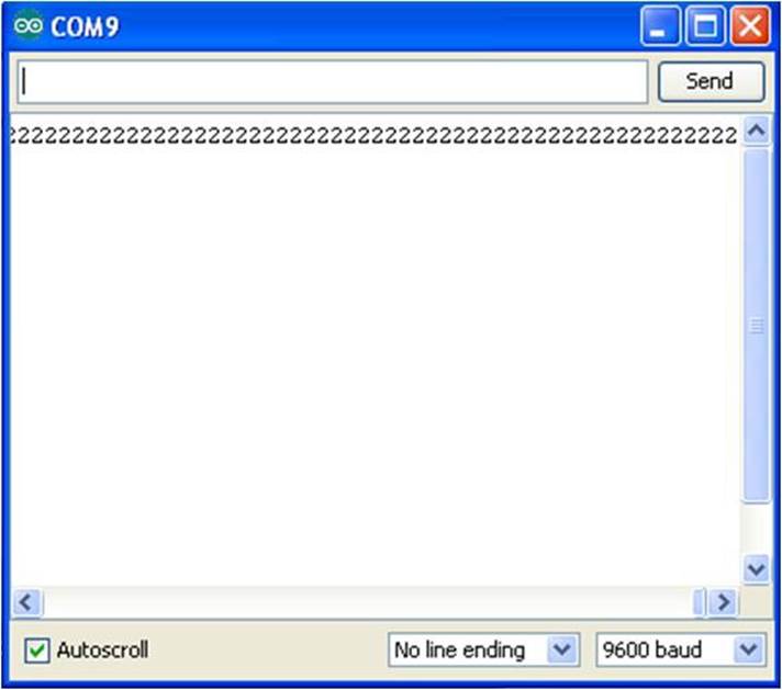
Figure 19-3. Decimal equivalent numbers being displayed on the Arduino Serial Monitor; pushbutton 3 has been pressed
0, 1, 2, AND … 4?
Why are the pushbuttons producing the numbers 0, 1, 2, and 4? What happened to 3? The answer is that the buttons have been programmed to count in binary, a number system that is based on the powers of 2. Zero is just that, zero. Two raised to the 0th power equals 1. Two raised to the 1st power equals 2. Two raised to the 2nd power equals 4.
Why the preoccupation with powers of two? As computers have two primary states (+5 volts and 0 volts), it’s easy to use those two states as the internal basis for everything the computer does. When computers need to count, add, or divide, they break the operation down into powers of two. In this project, instead of making the Arduino do the conversion, we’ve just started out using the powers of two.
Example 19-1. The MultiDigital4 sketch
/*
* MultiDigital4
*
* Reads 8 digital inputs and sends their values over the serial port.
* A byte variable is used to store the state of all eight pins. This byte
* is then sent over the serial port.
*
* modified ap_ReadDigital8 sketch by Melvin Oschmann
*
* 8 June 2013
* Don Wilcher
*
*/
// 8 variables for each pin
int digitalInput_1 = 3;
int digitalInput_2 = 4;
int digitalInput_3 = 5;
int digitalInput_4 = 6;
int digitalInput_5 = 7;
int digitalInput_6 = 8;
int digitalInput_7 = 9;
int digitalInput_8 = 10;
// 8 variables to store the values
int value_1 = 0;
int value_2 = 0;
int value_3 = 0;
int value_4 = 0;
int value_5 = 0;
int value_6 = 0;
int value_7 = 0;
int value_8 = 0;
// byte variable to send state of all pins over serial port
int myByte = 0;
// control LED
int controlLED = 13;
void setup(){
// set pin modes
pinMode(digitalInput_1, INPUT); pinMode(digitalInput_2, INPUT);
pinMode(digitalInput_3, INPUT); pinMode(digitalInput_4, INPUT);
pinMode(digitalInput_5, INPUT); pinMode(digitalInput_6, INPUT);
pinMode(digitalInput_7, INPUT); pinMode(digitalInput_8, INPUT);
pinMode(controlLED, OUTPUT);
// begin sending out over the serial port
Serial.begin(9600);
}
void loop(){
// set 'myByte' to zero
myByte = 0;
// then read all the INPUTS and store values
// in the corresponding variables
value_1 = digitalRead(digitalInput_1);
value_2 = digitalRead(digitalInput_2);
value_3 = digitalRead(digitalInput_3);
value_4 = digitalRead(digitalInput_4);
value_5 = digitalRead(digitalInput_5);
value_6 = digitalRead(digitalInput_6);
value_7 = digitalRead(digitalInput_7);
value_8 = digitalRead(digitalInput_8);
/* check if values are high or low and 'add' each value to myByte
* what it actually does is this:
*
* 00 00 00 00 ('myByte set to zero')
* | 00 10 10 00 ('3 and 5 are 1')
* --------------
* 00 10 10 00 ('myByte after logical operation')
*
*/
if (value_1) {
myByte = myByte | 0;
digitalWrite(controlLED, HIGH);
} else digitalWrite(controlLED, LOW);
if (value_2) { myByte = myByte | 1; }
if (value_3) { myByte = myByte | 2; }
if (value_4) { myByte = myByte | 4; }
if (value_5) { myByte = myByte | 8; }
if (value_6) { myByte = myByte | 16; }
if (value_7) { myByte = myByte | 32; }
if (value_8) { myByte = myByte | 64; }
// send myByte out over serial port and wait a bit to not overload the port
Serial.print(myByte);
delay(10);
}
The Rocket Launcher with Processing
The numbers from the MultiDigital4 sketch will be interpreted by Processing and used to drive a cool graphics screen, with color numbers and text. The layout of the Processing canvas is similar to the projects in Chapter 17 and Chapter 18 (with obvious differences in text and animation). After uploading the Rocket Game sketch to the Arduino, a jumbled blob of text and numbers along with a numbered grid will be displayed on your computer screen, as shown in Figure 19-4. If you look closely, you can see the word “rocket” repeated several times on the screen. Pressing pushbutton 1 will show the rocket launcher in action, as the text and associated number begin to rise on the numbered grid. Figure 19-5 shows an example of a virtual rocket being launched into the sky! Releasing the pushbutton allows the rocket to fall nicely back to earth.
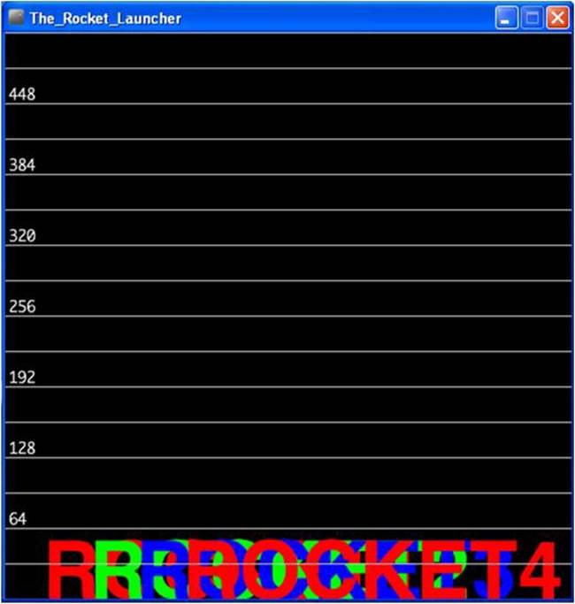
Figure 19-4. A blob of text and numbers
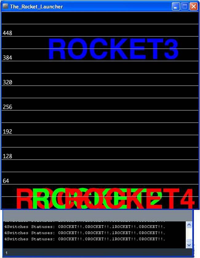
Figure 19-5. Rocket 3 being launched into the sky
Another cool feature of the Rocket Game Processing sketch (Example 19-2) is the Console Monitor located below the numbered grid. The Console Monitor displays the binary status of the pushbuttons and launched rockets. As shown in Figure 19-5, one of the pushbuttons has a binary status of 1, while the other three pushbuttons show a binary status of 0. From that, can you deduce which pushbutton has been pressed?
The Console Monitor can also be used as a sketch debugging tool when developing graphics, animation, and Arduino applications.
TECH NOTE
The Processing programming language allows text-based information to be displayed using a Console Monitor. The canvas is used to display graphics and animation information.
Example 19-2. The Rocket Game Processing sketch
/*
* The Rocket Game
*
* Reads the values which represent the state of 4 switches
* from the serial port and draws a graphical representation.
* Sketch inspired by Melvin Ochsmann's Multiple8 Switches
*
* 05 June 2013
* modified by Don Wilcher
*/
// importing the processing serial class
import processing.serial.*;
// the display item draws the background and grid
DisplayItems di;
// definition of window size and framerate
int xWidth = 512;
int yHeight = 512;
int fr = 12;
// attributes of the display
boolean bck = true;
boolean grid = true;
boolean g_vert = false;
boolean g_horiz = true;
boolean g_values = true;
boolean output = true;
// variables for serial connection, port name, and baud rate have to be set
Serial port;
// establish serial port connection
// The "2" corresponds to the 3rd port (counting from 0) on the Serial
// Port list dropdown. You might need to change the 2 to something else.
String portname =Serial.list()[2];
int baudrate = 9600;
int value = 0;
// variables to draw graphics
int i;
// if you would like to change fonts, make sure the font file (which
// can be created with Processing) is in the data directory
String fontname2 = "Helvetica-Bold-96.vlw";
int fontsize2 = 72; // change size of text on screen
PFont font2;
float valBuf[] = new float[8];
int xpos, ypos;
// lets user control DisplayItems properties and value output in console
void keyPressed(){
if (key == 'b' || key == 'B') bck=!bck; // background black/white
if (key == 'g' || key == 'G') grid=!grid; // grid on/off
if (key == 'v' || key == 'V') g_values=!g_values; // grid values on/off
if (key == 'o' || key == 'O') output=!output; //turns value output on/off
}
void setup(){
// set size and framerate
size(xWidth, yHeight); frameRate(fr);
// establish serial port connection
port = new Serial(this, portname, baudrate);
println(port);
// create DisplayItems object
di = new DisplayItems();
// load second font for graphical representation and clear value buffer
font2 = loadFont(fontname2);
for(i = 0; i < valBuf.length; i++ ){
valBuf[i] = (height/2);
}
}
void drawFourSwitchesState(){
textFont(font2, fontsize2);
if (output) print("4Switches Statuses: ");
// takes value, interprets it as a byte
// and reads each bit
for (i=0; i < 4 ; i++){
if(output) print(value & 1);
print("ROCKET!");
// if a bit is 1, increase the corresponding value in value buffer
// array by 1
if ( (value & 1) == 1){ // if 0, number drops when pushbutton is
// pressed; if 1, number goes up when
// pushbutton is pressed
if(valBuf[i] > fontsize2 ) valBuf[i] -=1;
// if a bit is 0, decrease corresponding value
}else{
if(valBuf[i] < height) valBuf[i] += 1;
}
if(output)
print(".");
// draw number for each value at its current height
fill( ( (i%3==0) ? 255 : 0 ),
( (i%3==1) ? 255 : 0 ) ,
( (i%3==2) ? 255 : 0 ));
text( ( "ROCKET"+(i+1) ),
(i*(width/12)) + (width/15),
valBuf[i]); // prints "ROCKET" along with number
value = value >> 1;
} // end for loop
if(output)
println("");
}
void draw(){
// listen to serial port and set value
while(port.available() > 0){
value = port.read();
}
// draw background, then four switches and finally rest of DisplayItems
di.drawBack();
drawFourSwitchesState();
di.drawItems();
}
Next, the DisplayItems sketch is required for the interaction of the Rocket Game and the computer graphics to be visible on your computer screen. Enter the DisplayItems sketch shown in Example 19-3 into the Processing IDE text editor. Note that a second tab needs to be inserted within the IDE for the DisplayItems sketch. After typing the sketch, click the play button to obtain the image shown in Figure 19-4. Press a pushbutton on the Arduino breadboard and watch the rocket move up your computer screen, as shown in Figure 19-5.
TECH NOTE
There are a couple of Easter eggs embedded in the Rocket Game Processing sketch that allow you to change the appearance of the display. Also, the onboard LED turns on with one of the pushbuttons. Good Hunting!
Example 19-3. The DisplayItems Processing sketch
/*
* DisplayItems
*
* This class draws background color, grid and value scale
* according to the boolean variables in the Rocket Launcher file.
*
* This file is part of the Arduino meets Processing Project.
* For more information visit http://www.arduino.cc.
*
* created 2005 by Melvin Ochsmann for Malmo University
*
*/
class DisplayItems{
// variables of DisplayItems object
PFont font;
int gridsize;
int fontsize = 10;
String fontname = "Monaco-14.vlw";
String empty="";
int i;
// constructor sets font and fontsize
DisplayItems(){
font = loadFont(fontname);
gridsize = (width/2)/16+(height/2)/16;
if(gridsize > 20) fontsize = 14;
if(gridsize > 48) fontsize = 22;
}
// draws background
void drawBack(){
background( (bck) ? (0) : (255) );
}
// draws grid and value scale
void drawItems(){
textFont(font, fontsize);
if(grid){ stroke( (bck) ? (200) : (64) );
fill((bck) ? (232) : (32) );
// vertical lines
if(g_vert){
for (i=0; i < width; i+=gridsize){
line(i, 0, i, height);
textAlign(LEFT);
if (g_values &&
i%(2*gridsize)==0
&& i < (width-(width/10)))
text( empty+i, (i+fontsize/4), 0+fontsize);
}}
// horizontal lines
if(g_horiz){
for (int i=0; i < height; i+=gridsize){
line(0, i, width, i);
textAlign(LEFT);
if (g_values &&
i%(2*gridsize)==0)
text( empty+(height-i), 0+(fontsize/4), i-(fontsize/4));
}}
}
}
}// end class Display
TECH NOTE
The size of the letters can be changed with the fontsize variable.
The block diagram in Figure 19-6 shows the electronic component blocks and the data flow for the Rocket Game. A Fritzing electronic circuit schematic diagram of the gadget is shown in Figure 19-7. Electronic circuit schematic diagrams are used by electrical/electronic engineers to design and build cool interactive electronic products for society.
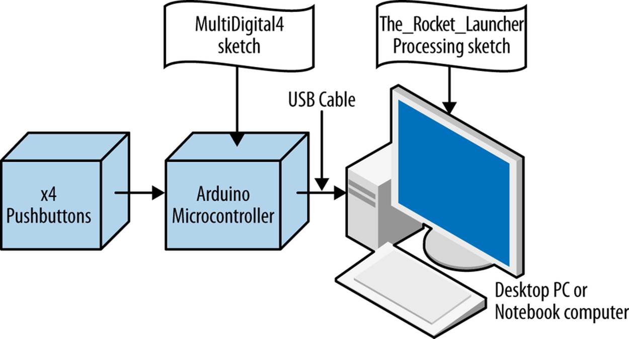
Figure 19-6. The Rocket Game block diagram
Something to Think About
How can the word “ROCKET” be replaced with “FIRE” within the Rocket Game Processing sketch?
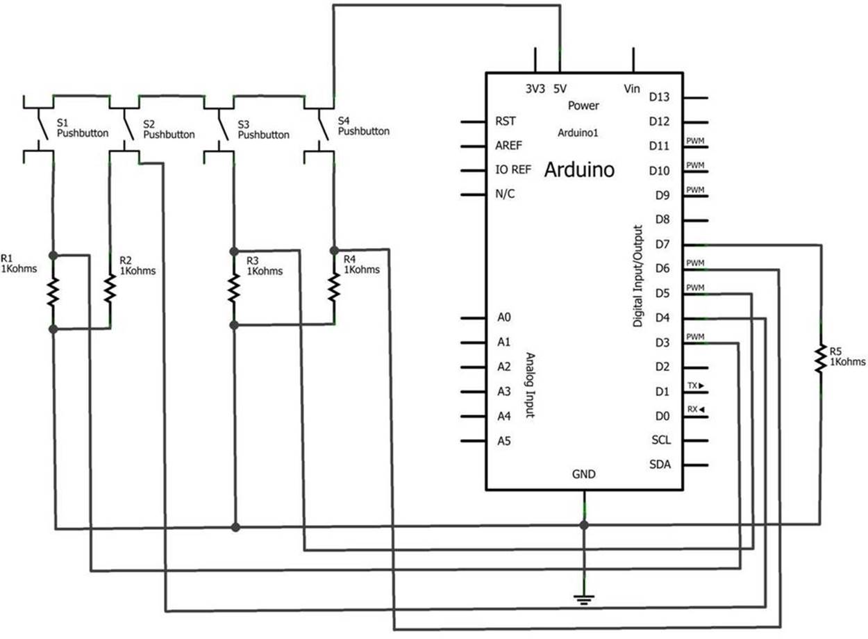
Figure 19-7. The Rocket Game Fritzing circuit schematic diagram
All materials on the site are licensed Creative Commons Attribution-Sharealike 3.0 Unported CC BY-SA 3.0 & GNU Free Documentation License (GFDL)
If you are the copyright holder of any material contained on our site and intend to remove it, please contact our site administrator for approval.
© 2016-2026 All site design rights belong to S.Y.A.