Make: Basic Arduino Projects - 26 Experiments with Microcontrollers and Electronics (2014)
Chapter 21. Sweeping Servo
An Electrical Motor Tester
Chapter 3 has an awesome project that changes a servo motor’s angle of rotation based on the orientation of a tilt sensor. In that project, rotating the tilt sensor to either 0° or 90° positions will make the servo motor’s shaft turn CW (clockwise) or CCW (counterclockwise). Also, the tilt sensor, along with the servo motor, can be used to build a simple animatronic controller for robotic puppets.
In this chapter, you can build a cool electrical tester to quickly test the limits of the Ultimate Microcontroller Pack servo motors, or those you may obtain outside the kit, like from a local Makerspace’s electrical/mechanical parts bin.
The electronic components to build this electrical tester are shown in the Parts List. The Sweeping Servo Motor Tester is shown in Figure 21-1.
Parts List
§ Arduino microcontroller
§ MakerShield kit
§ M1: DC servo motor

Figure 21-1. The Sweeping Servo Motor Tester
Let’s Build a Servo Motor Tester
The Servo Motor Tester is quite simple to build and only requires the three components shown in the Parts List. With this tester, you will be able to quickly check any of the small voltage-based servo motors you may have in your junk box. The Servo Motor Tester can be built using the Fritzing wiring diagram shown in Figure 21-2. Since the major component for this project is the servo motor, placement of the parts on the breadboard is not critical. You have lots of room to explore different ways to place the servo motor when laying out the circuit on the breadboard.
In addition, by inserting the appropriate size solid wires into the three-pin female connector, you can easily make a male connecting component. This homebrew male connector makes it easy to insert the servo motor into a breadboard. (For further reference on building a servo motor male connector, see Figure 3-4 in Chapter 3.) Although the Fritzing wiring diagram shows a small breadboard, you can also use the MakerShield protoboard to build the Servo Motor Tester.
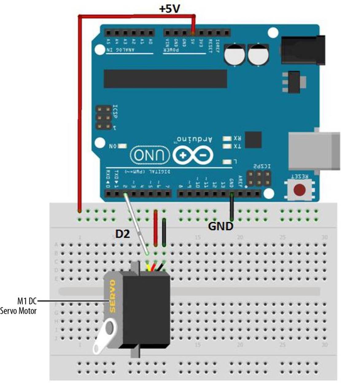
Figure 21-2. The Servo Motor Tester Fritzing wiring diagram
TECH NOTE
The color-coded wires for the Ultimate Microcontroller Pack are yellow (to D2), red (to +5V), and brown (to GND).
Upload the Sweeping Sketch
With the Servo Motor Tester built on the breadboard, now it’s time to upload an Arduino sketch. Before uploading the sketch, check for wiring errors and make sure the servo motor connector is correctly attached to the breadboard. Example 21-1 sends a series of electrical pulses from the Arduino microcontroller’s digital pin D9 to the servo motor. Here are the steps you’ll need to follow:
1. Attach the Arduino microcontroller to your computer using a USB cable.
2. Open the Arduino software and type Example 21-1 into the software’s text editor.
3. Upload the sketch to the Arduino microcontroller.
With the Sweeping sketch uploaded to the Arduino microcontroller, the servo motor will begin rotating CW and CCW continuously. Figure 21-3 shows a servo motor being tested by the Sweeping sketch.

Figure 21-3. A servo motor being tested using the Sweeping sketch
TECH NOTE
The size of the pulse width determines the servo motor’s angle of rotation.
Example 21-1. The Sweeping sketch
#include <Servo.h>
Servo myservo; // create servo object to control a servo
// a maximum of eight servo objects can be created
int pos = 0; // variable to store the servo position
void setup()
{
myservo.attach(2); // attaches the servo on pin 2 to the servo object
}
void loop()
{
for(pos = 0; pos < 170; pos += 1) // goes from 0 degrees to 170 degrees
{ // in steps of 1 degree
myservo.write(pos); // move to position in variable 'pos'
delay(15); // waits 15ms to reach the position
}
for(pos = 170; pos>=1; pos-=1) // goes from 170 degrees to 0 degrees
{
myservo.write(pos); // move to position in variable 'pos'
delay(15); // waits 15ms to reach the position
}
}
One final point to make about the Sweeping sketch: with some servo motors, a 180° pulse may cause the gears to grind. Therefore, experiment (gently!) with this value to learn the maximum CW and CCW rotation of your particular servo, without grinding the servo motor’s gears.
TECH NOTE
In Chapter 5 of Make: Electronics, there is a nice reference page describing various DC motors, including the servo motor.
The block diagram in Figure 21-4 shows the electronic component blocks and the data flow. The equivalent Fritzing electronic circuit schematic diagram of the Servo Motor Tester is shown in Figure 21-5.

Figure 21-4. The Servo Motor Tester block diagram
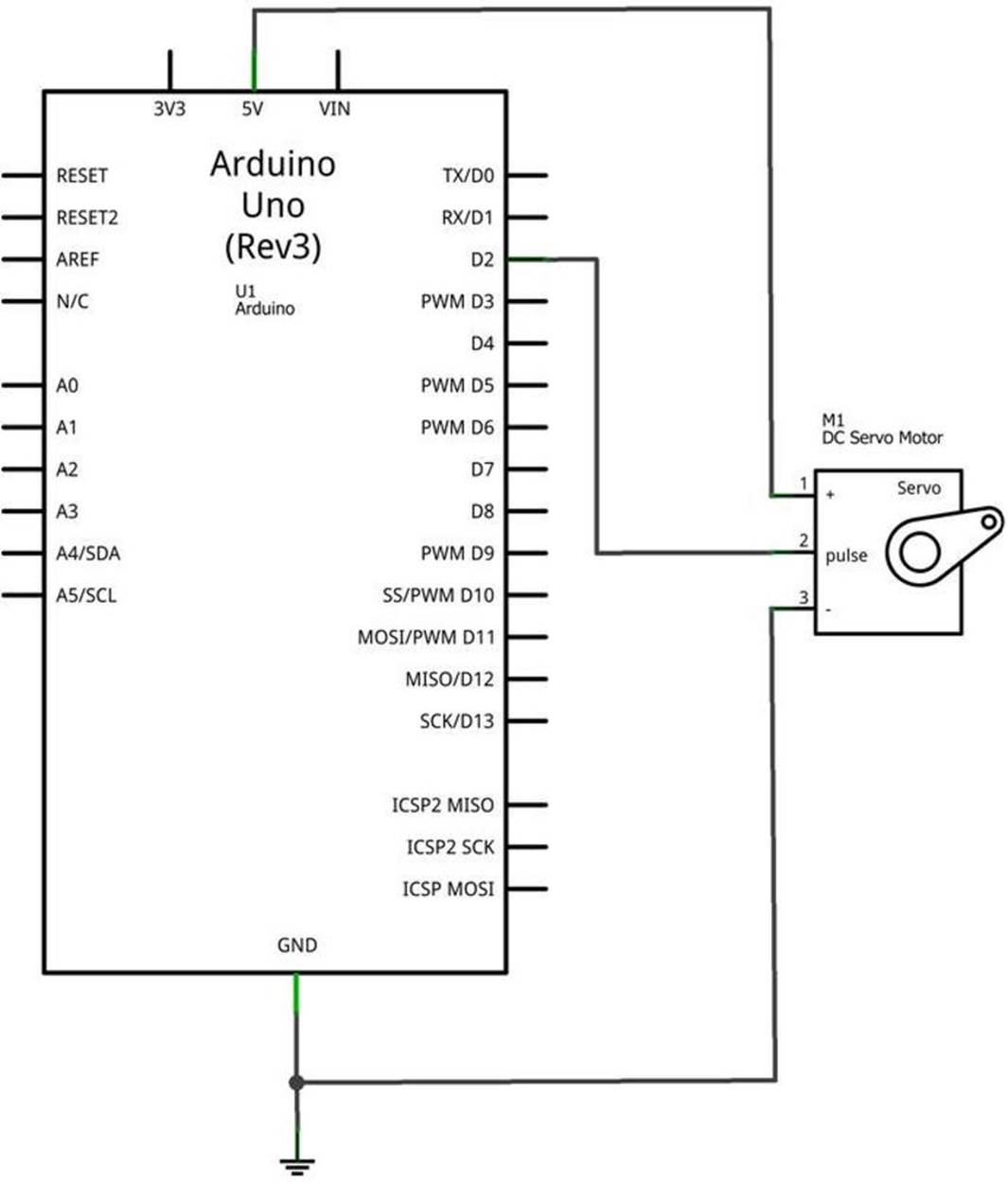
Figure 21-5. The Servo Motor Tester Fritzing circuit schematic diagram
Something to Think About
How can an LED be wired to the Arduino microcontroller to light up when the servo motor is at 180°?
All materials on the site are licensed Creative Commons Attribution-Sharealike 3.0 Unported CC BY-SA 3.0 & GNU Free Documentation License (GFDL)
If you are the copyright holder of any material contained on our site and intend to remove it, please contact our site administrator for approval.
© 2016-2026 All site design rights belong to S.Y.A.