Make: Basic Arduino Projects - 26 Experiments with Microcontrollers and Electronics (2014)
Chapter 23. A Pocket Stage Light
Temperature Sensing (Part 2)
Stage lighting provides a cool effect for concerts and plays. The various color lenses placed on the lights are used to complement the mood of the performers on stage. How awesome would it be to have an electronic gadget that can project colors on a wall without using special lenses and light bulbs? You’ll be able to perform a magnificent lighting show for your family, friends, and local Makerspace members anywhere at any time. Also, the pocket lighting device can be operated by touch instead of pushbutton switches. With electronic parts obtained from the Ultimate Microcontroller Pack, you can build your own Pocket Stage Light. The electronic components to build the Pocket Stage Light are shown in the Parts List. The assembled Pocket Stage Light is shown in Figure 23-1.
Parts List
§ Arduino microcontroller
§ MakerShield kit
§ R1: negative temperature coefficient (NTC) thermistor (green or black candy drop; part number 503)
§ R2: 10KΩ resistor (brown, black, orange stripes)
§ R3: 1KΩ resistor (brown, black, red stripes)
§ R4: 330Ω resistor (orange, orange, brown stripes)
§ LED1: RGB LED
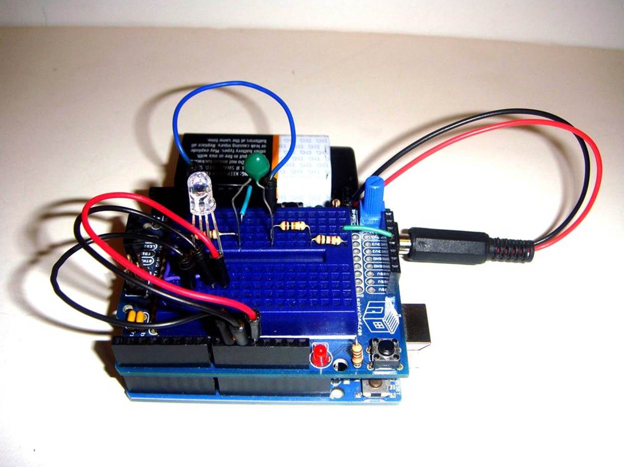
Figure 23-1. The assembled Pocket Stage Light
Let’s Build a Pocket Stage Light
Operating an electronic gadget with sensors is called physical computing. Other examples of physical computing devices are Microsoft’s Kinect and smartphone touch screens. The Pocket Stage Light is operated by warm temperature. The temperature value is changed to an electrical voltage and used by the Arduino microcontroller to turn on an RGB LED. Control over the color lighting sequence of red, green, and blue is provided by an Arduino sketch.
Use the Fritzing wiring diagram shown in Figure 23-2 to build the Pocket Stage Light. Touching the thermistor with your finger will signal the Arduino microcontroller to turn on the red, green, and blue colors of the LED in sequence. After you release the thermistor, the color LEDs will continue to sequence for approximately 10 seconds.
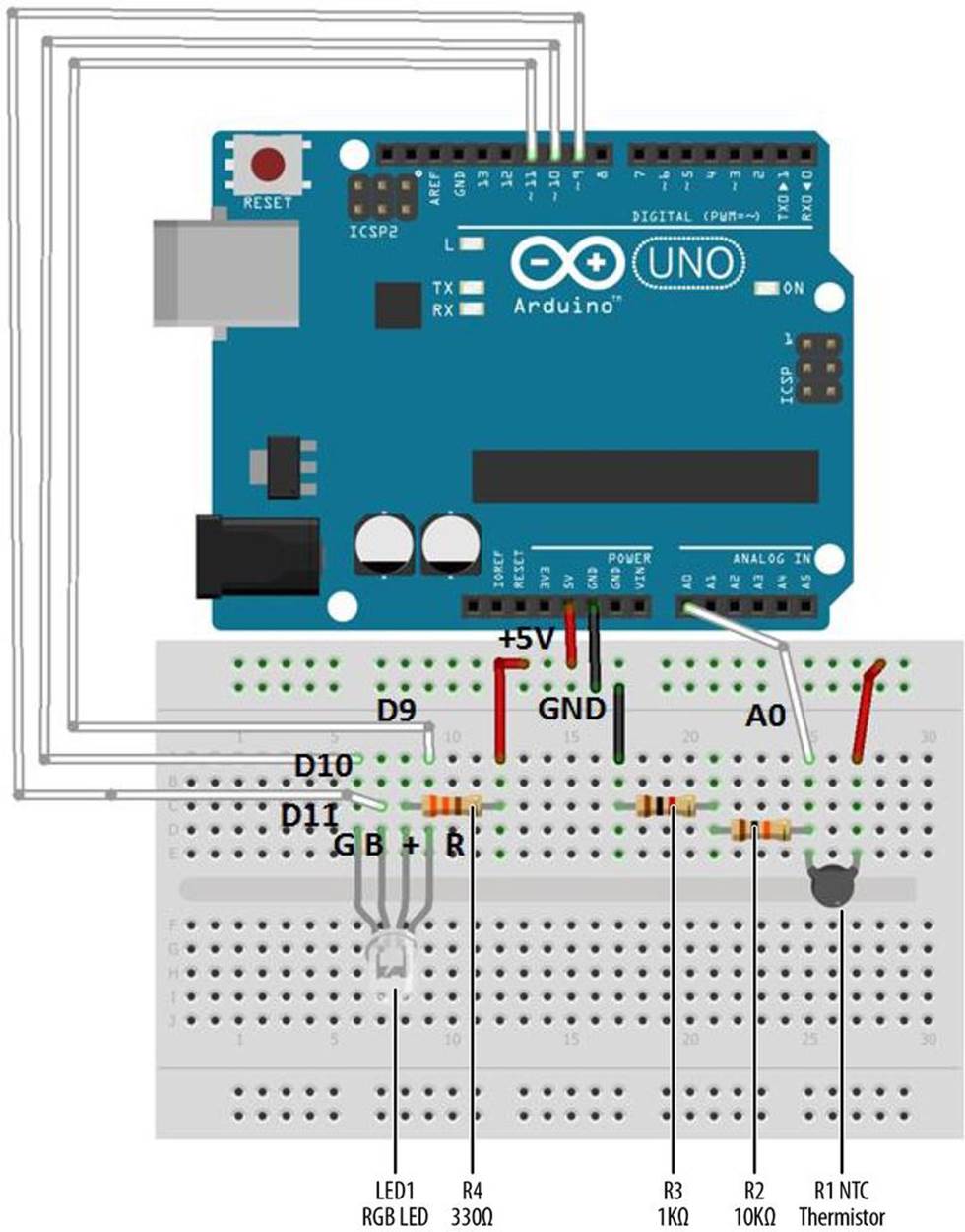
Figure 23-2. Pocket Stage Light Fritzing wiring diagram
Before uploading the sketch in Example 23-1 to the Arduino, check and correct any wiring errors on your breadboard using the Fritzing diagram shown in Figure 23-2.
TECH NOTE
With the right color mix, you can create a white light with an RGB LED. Check out Wikipedia’s page on the RGB color model.
Upload the Pocket Stage Light Sketch
With the Pocket Stage Light wired on the breadboard, now it’s time to upload the Arduino sketch. Example 23-1 turns on three Arduino microcontroller digital pins (D9, D10, and D11) in sequence that operate the red, green, and blue portion of the RGB LED. Here are the steps you’ll need to follow:
1. Attach the Arduino microcontroller to your computer using a USB cable.
2. Open the Arduino software and type Example 23-1 into the software’s text editor.
3. Upload the sketch to the Arduino microcontroller.
The Arduino microcontroller is now programmed with the Pocket Stage Light sketch. When the sketch starts running, the RGB LED is off. Touch the thermistor with your finger, and the RGB LED will begin to sequence its red, green, and blue colors. Releasing the sensor will allow the color sequencing to continue for approximately one second. Figure 23-3 and Figure 23-4 show the operation of the Pocket Stage Light.
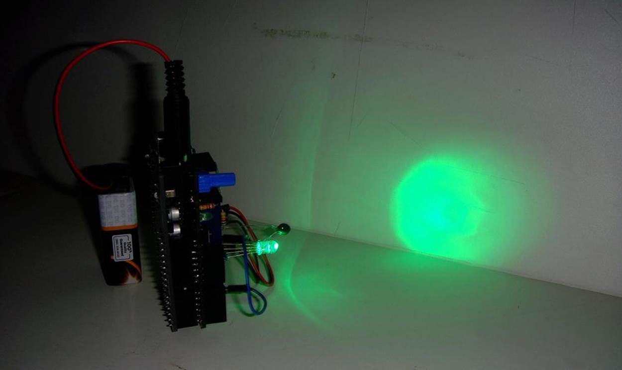
Figure 23-3. Pocket Stage Light projecting a green light on a whiteboard
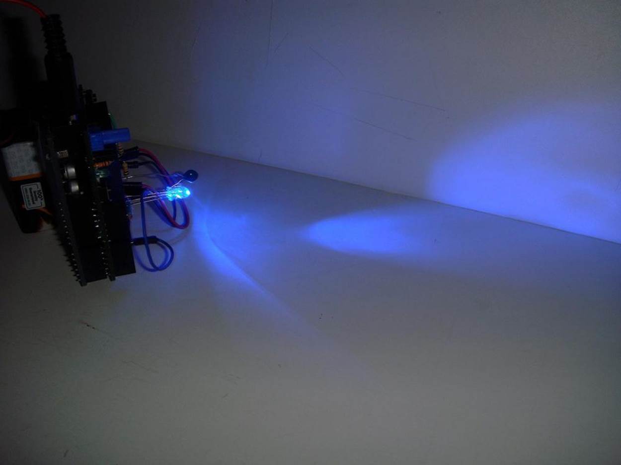
Figure 23-4. Pocket Stage Light projecting a blue light on a whiteboard
Example 23-1. Pocket Stage Light sketch
/*
Pocket Stage Light
The RGB LED will sequence in colors (blue, green, red) by use
of a thermistor.
15 August 2013
by Don Wilcher
*/
int tsensorPin = A0; // select the input pin for the temperature sensor
int RPin = 11; // select the pin for the red LED
int GPin = 10; // select the pin for the green LED
int BPin = 9; // select the pin for the blue LED
int tsensorValue = 0; // to store the value from the temperature sensor
void setup() {
// declare the LED pins as outputs:
pinMode(RPin, OUTPUT);
pinMode(GPin, OUTPUT);
pinMode(BPin, OUTPUT);
Serial.begin(9600);
}
void loop() {
// read the value from the sensor:
tsensorValue = analogRead(tsensorPin);
Serial.println(tsensorValue);
delay(100);
if (tsensorValue > 190){
// turn the blue LED on:
digitalWrite(BPin, LOW);
digitalWrite(RPin, HIGH);
// delay blue LED for 5 seconds:
delay(5000);
// turn the green LED on:
digitalWrite(BPin, HIGH);
digitalWrite(GPin, LOW);
// delay green LED for 5 seconds:
delay(5000);
// turn the red LED on:
digitalWrite(GPin, HIGH);
digitalWrite(RPin, LOW);
//delay red LED for 5 seconds:
delay(5000);
}
else{
// turn blue, green, and red LEDs off:
digitalWrite(BPin, HIGH);
digitalWrite(GPin, HIGH);
digitalWrite(RPin, HIGH);
}
}
You can see the thermistor’s output on the Arduino’s Serial Monitor. Also, as discussed in Chapter 22, you can experiment with a 10KΩ thermistor to see a difference in the RGB LEDs response. Observe the operation of the RGB LED closely to see a different turn-on response based on the 10KΩ thermistor component. Last, change the color sequence of the LEDs from the order listed within the sketch! Remember to record your software and electrical design changes in a lab notebook.
TECH NOTE
The Serial Monitor is a tool used to display electrical data of all types of sensors wired to the Arduino microcontroller.
The block diagram in Figure 23-5 shows the electronic component blocks and the data flow for the Pocket Stage Light. Also, the equivalent Fritzing electronic circuit schematic diagram of the portable lighting device is shown in Figure 23-6. Circuit schematic diagrams allow electronic devices to be built quickly. Electrical/electronic engineers and technicians use them to design, build, and test cool interactive electronic products for games, testing equipment, robots, and automobiles.
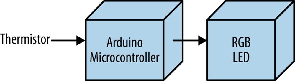
Figure 23-5. The Pocket Stage Light block diagram
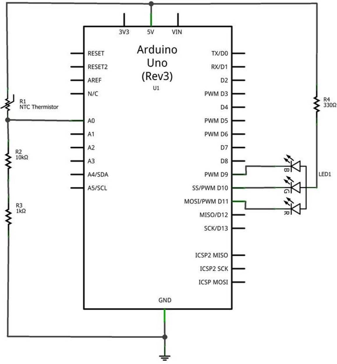
Figure 23-6. The Pocket Stage Light Fritzing circuit schematic diagram
Something to Think About
Does a 10KΩ thermistor have a faster RGB LED turn-on response compared to the Ultimate Microcontroller Pack’s sensing component?
All materials on the site are licensed Creative Commons Attribution-Sharealike 3.0 Unported CC BY-SA 3.0 & GNU Free Documentation License (GFDL)
If you are the copyright holder of any material contained on our site and intend to remove it, please contact our site administrator for approval.
© 2016-2026 All site design rights belong to S.Y.A.