Make: Basic Arduino Projects - 26 Experiments with Microcontrollers and Electronics (2014)
Chapter 24. Electronic Pixel
Serial Communications
In nearly all the cool video games you play, the graphics are complex and sophisticated. The images seem real, and their movement is smooth and natural. The magic behind these cool computer graphic images is just a dot of light called a pixel, short for “picture element.” The game you’re playing calculates what the color value of each of the pixels on your screen should be; together, these pixels are arranged to create an image. This project is going to be just like taking one pixel from a monitor and controlling its state using a computer and an Arduino microcontroller. The electronic components to build the pixel project are shown in the Parts List. The assembled Electronic Pixel is shown in Figure 24-1.
Parts List
§ Arduino microcontroller
§ MakerShield kit
§ R1: 330Ω resistor (orange, orange, brown stripes)
§ S1: DPDT (double pole, double throw) switch
§ LED1: RGB LED
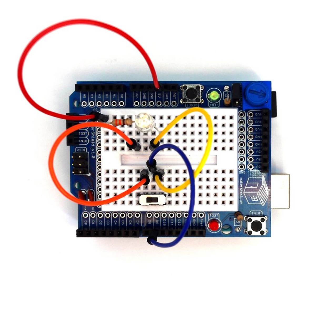
Figure 24-1. The assembled Electronic Pixel
Let’s Build an Electronic Pixel
In the case of the Electronic Pixel, the LED on and off commands are sent from the Arduino’s Serial Monitor and converted into equivalent voltage pulses. These voltage pulses are sent through a USB cable attached between the computer and the Electronic Pixel. Digital pin D9 of the Arduino microcontroller is used to turn on and off the RGB LED.
The Electronic Pixel is built using a breadboard with the components wired to each other, as shown in Figure 24-2. Although the Fritzing wiring diagram shows the Electronic Pixel built on a breadboard, the MakerShield protoboard can be used as well. Also, the Fritzing wiring diagram shows a single pole, double throw (SPDT) switch instead of the double pole, double throw (DPDT) electrical component shown in the Parts List. The remainder of the DPDT switch can be wired as shown in Figure 24-2. Refer to Chapter 5 for additional instructions on how to set up the DPDT switch for breadboarding.
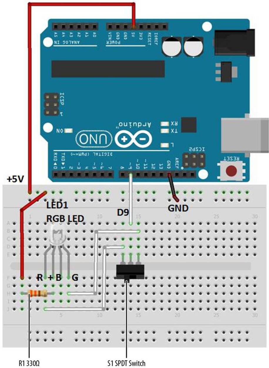
Figure 24-2. The Electronic Pixel Fritzing wiring diagram
TECH NOTE
Remember from an earlier chapter that on and off voltage pulses are known as binary data. The two numbers that represent binary data are 1 and 0. The electrical voltage value for binary 1 is +5 volts and 0 is equal to 0 volts.
Upload the Electronic Pixel Sketch
Before uploading Example 24-1 to the Arduino, check and correct any wiring errors on your breadboard using the Fritzing diagram shown in Figure 24-2. With the Electronic Pixel wired on the breadboard, it is now time to upload the Arduino sketch. Here are the steps you’ll need to follow:
1. Attach the Arduino microcontroller to your computer using a USB cable.
2. Open the Arduino software and type Example 24-1 into the software’s text editor.
3. Upload the sketch to the Arduino microcontroller.
The Arduino microcontroller is now programmed with the Electronic Pixel sketch. The RGB LED is turned on at this point. The green or red LED might be turned on based on the DPDT switch position. As mentioned in the introduction, an electrical switch is wired to the Arduino microcontroller’s digital pin to create a cool interactive effect using the colors of the RGB LED. Slide the switch back and forth and watch the RGB LED toggle between the colors red and green (see Figure 24-3 and Figure 24-4).
Now, open the Arduino Serial Monitor and type the letter “L” into the text box. Press Enter on your computer. The RGB LED is turned off. Type the letter “H” into the text box and click the Serial Monitor “send” button. The RGB LED turns on. If the project is not working properly, find any sketch errors and correct them. Upload the corrected sketch to the Arduino microcontroller and retest the Electronic Pixel.
Example 24-1. The Electronic Pixel sketch
/*
Electronic Pixel
An example of using an Arduino microcontroller for serial communication to
receive binary data from a computer. In this case, the Arduino boards
turns on an RGB LED when it receives the 'H' character, and turns off
the RGB LED when it receives the 'L' character. Also, an electrical
switch can change the colors of the RGB LED between green and red.
The on and off command data can be sent from the Arduino
Serial Monitor.
*/
int ledPin = 9; // the pin that the RGB LED is attached to
int incomingByte; // a variable to read incoming serial data
void setup() {
// initialize serial communication:
Serial.begin(9600);
// initialize the RGB LED pin as an output:
pinMode(ledPin, OUTPUT);
}
void loop() {
// see if there's incoming serial data:
if (Serial.available() > 0) {
// read the oldest byte in the serial buffer:
incomingByte = Serial.read();
// if it's a capital H, turn on the LED:
if (incomingByte == 'H') {
digitalWrite(ledPin, LOW);
}
// if it's an L, turn off the LED:
if (incomingByte == 'L') {
digitalWrite(ledPin, HIGH);
}
}
}
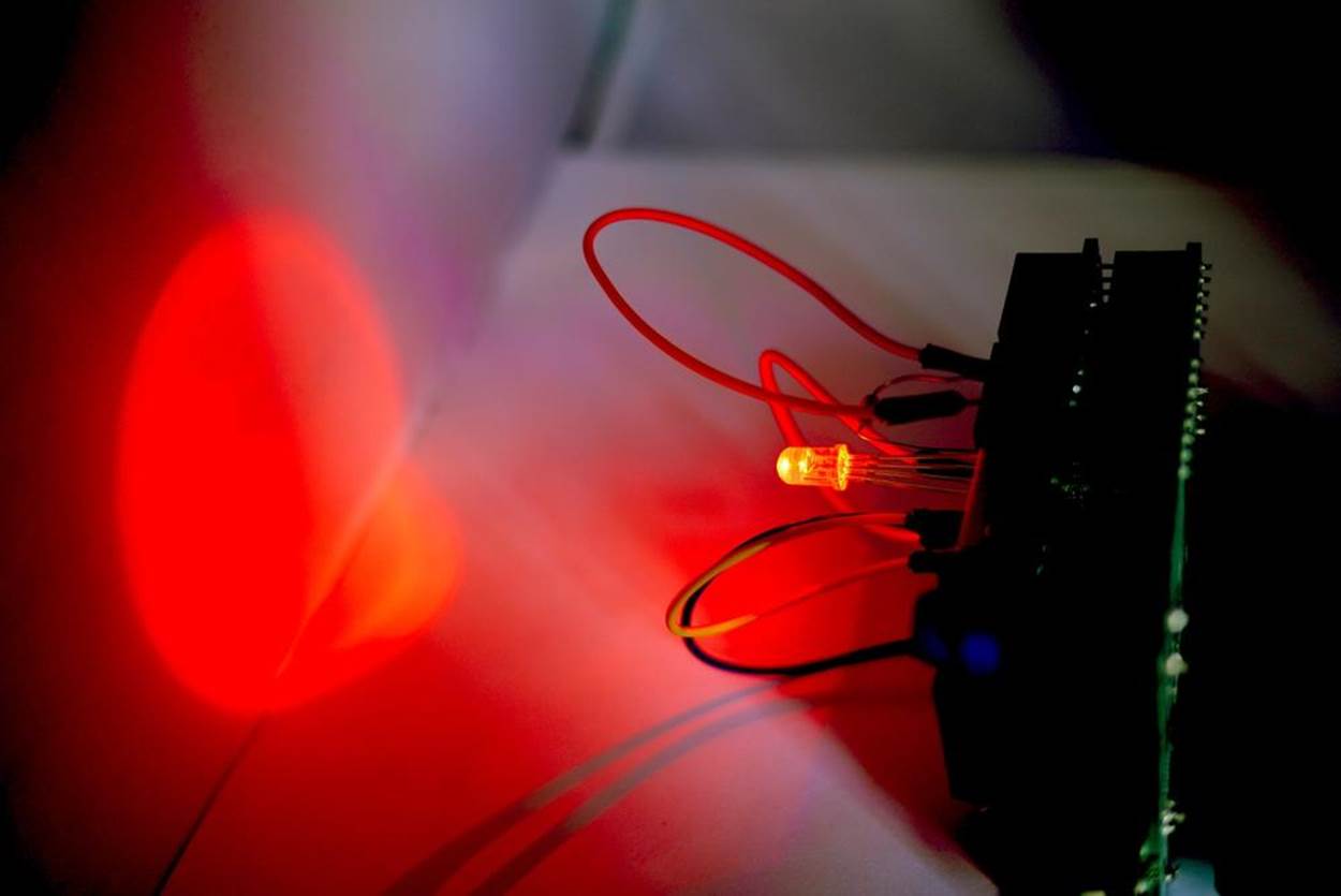
Figure 24-3. A very large red pixel projected onto a whiteboard
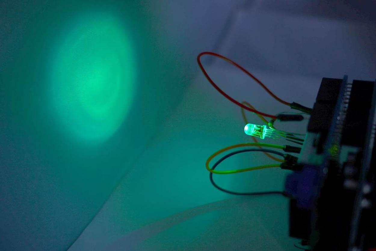
Figure 24-4. A green ghost projected onto a whiteboard
TECH NOTE
Any computer keyboard characters can be used to operate the RGB LED. Look at Example 24-1 and replace the letters “H” and “L” with the different keyboard characters.
The block diagram in Figure 24-5 shows the circuit component blocks and the data flow for the Electronic Pixel. Also, the equivalent Fritzing electronic circuit schematic diagram of the Electronic Pixel is shown in Figure 24-6.
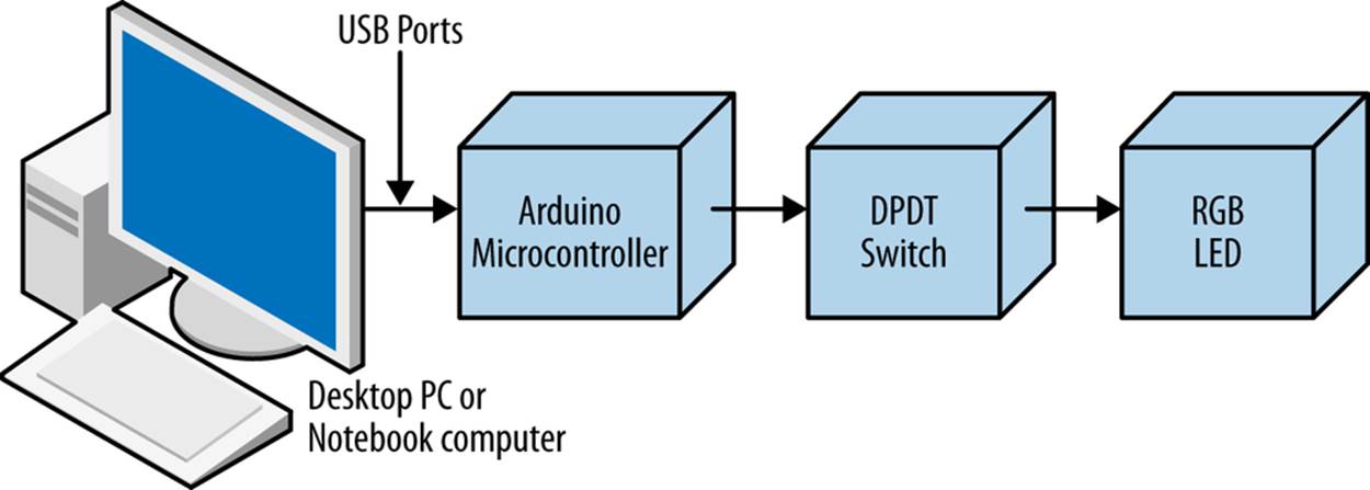
Figure 24-5. The Electronic Pixel block diagram
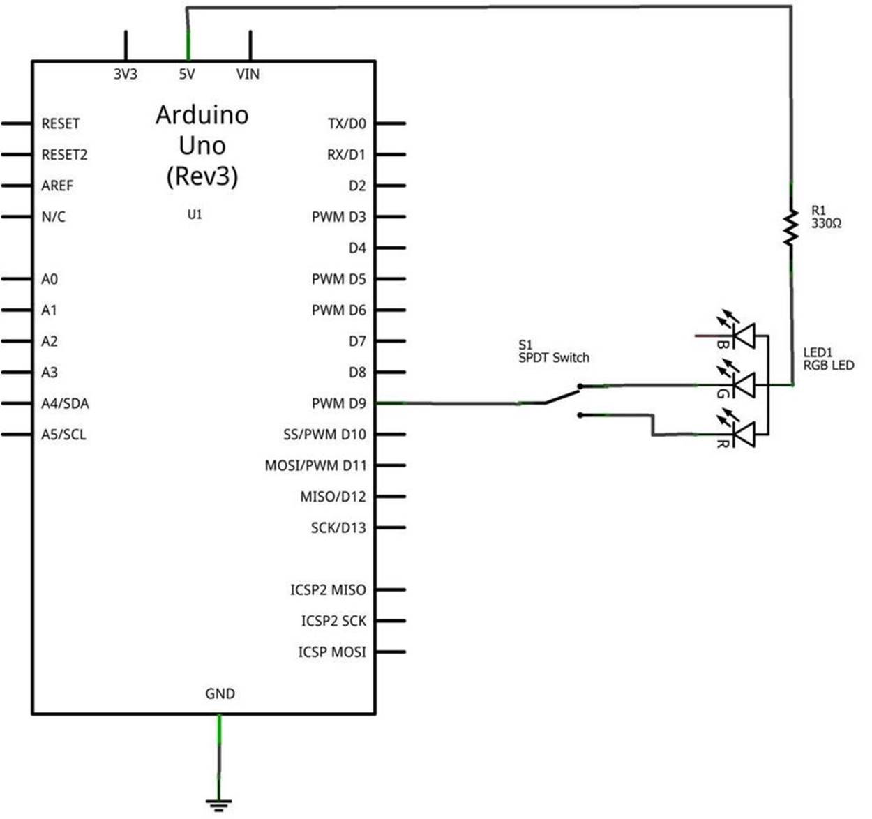
Figure 24-6. The Electronic Pixel Fritzing circuit schematic diagram
Something to Think About
How can the switching sequence between the red, green, and blue LEDs be changed to operate faster?
All materials on the site are licensed Creative Commons Attribution-Sharealike 3.0 Unported CC BY-SA 3.0 & GNU Free Documentation License (GFDL)
If you are the copyright holder of any material contained on our site and intend to remove it, please contact our site administrator for approval.
© 2016-2026 All site design rights belong to S.Y.A.