Make: Basic Arduino Projects - 26 Experiments with Microcontrollers and Electronics (2014)
Chapter 6. The AND Logic Gate
Two Pushbutton Switches in Series
The AND Logic Gate is another computer circuit used to make basic decisions with electrical input signals. Building the AND Logic Gate requires wiring two pushbutton switches to electrical contacts in a chain or series circuit. The AND Logic Gate’s output decision is based on both parts of the input data (i.e., both pushbutton switches) being in the same state.
In this chapter, you will learn about the AND Logic Gate by building an Arduino-based AND Logic Gate using a photocell, a pushbutton switch, and an LED. Figure 6-1 shows the assembled Arduino AND Logic Gate. The Ultimate Microcontroller Pack has all of the electronic parts to build this interactive tutorial device.
Parts List
§ Arduino microcontroller
§ MakerShield kit
§ S1: pushbutton switch
§ S2: pushbutton switch
§ R1: 1KΩ resistor (brown, black, red stripes)
§ R2: 10KΩ potentiometer (for basic AND Logic Gate circuit)
§ R2: photocell (for Arduino AND Logic Gate circuit)
§ R3: 1KΩ resistor (brown, black, red stripes) for basic AND Logic Gate circuit
§ R3: 10KΩ resistor (brown, black, orange stripes) for Arduino AND Logic Gate circuit
§ R4: 330Ω resistor (orange, orange, brown stripes)
§ LED1: green LED (for Arduino AND Logic Gate circuit)
§ LED1: red LED (for basic AND Logic Gate circuit)
§ Battery1: 3VDC battery pack
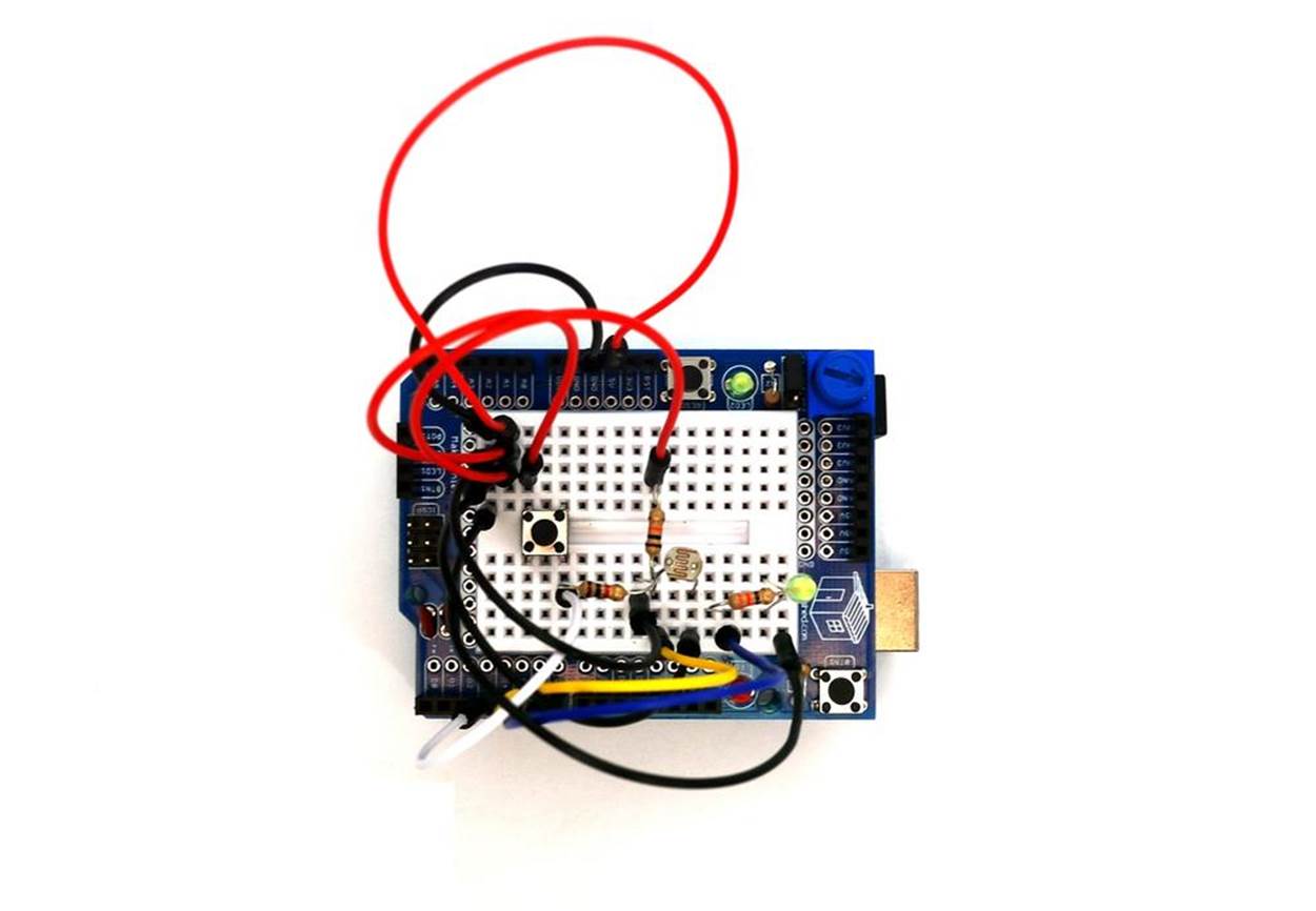
Figure 6-1. The assembled Arduino AND Logic Gate
TECH NOTE
In digital electronics, a TRUE state is when a data bit is set to 1, or an output pin is set to +5 volts, or a switch is closed. A FALSE state is when a data bit equals 0, or an output pin is set to 0 volts, or a switch is open.
Circuit Theory
The AND Logic Gate is a computer circuit that outputs TRUE if the two pieces of input data have the same state as each other. Digital electronics have two binary states: TRUE or FALSE. The electric circuits used in digital electronics to build computer logic gates will either be closed or open representing a TRUE or FALSE state.
The schematic diagram in Figure 6-2 shows a basic AND Logic Gate electric circuit in two different states. On the left, we see the circuit with both pushbutton switches open. In this state, the output for both pushbutton switches is FALSE, and the LED will be off. On the right, we see the circuit when both switches are closed. In this state, the output is TRUE, and the LED will be on.
The operation of the AND Logic Gate can easily be programmed into an Arduino microcontroller, as shown in Figure 6-1. Creating an Arduino AND Logic Gate requires a few basic electronic components found in the Ulitmate Microcontroller Pack. The logical AND operator is part of the Arduino sketch library. The Arduino AND Logic Gate will turn on an LED when two inputs are both TRUE and are logical HIGH. Why Use an Arduino Microcontroller to Build an AND Logic Gate? explains the advantages of using a smart chip to create logical gate functions.
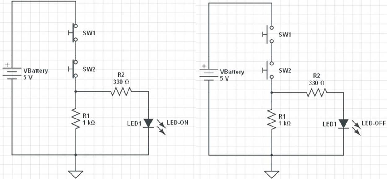
Figure 6-2. Circuit schematic diagram showing an AND Logic Gate controlling an LED
TECH NOTE
When electrical/electronic components are connected with the output of one component becoming the input of the next, we say that they have made a series circuit.
Figure 6-3 shows the Fritzing wiring diagram.
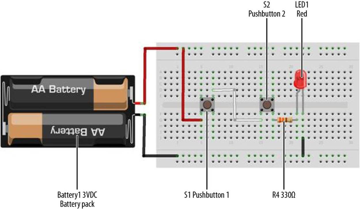
Figure 6-3. The AND Logic Gate Fritzing wiring diagram; the flat side of the LED is the negative pin
Just like the NOT Logic Gate discussed in Chapter 5, the AND Logic Gate has a special circuit symbol, shown in Figure 6-4. The truth table (TT) shows the logic gate operation. Figure 6-5 is an AND Logic Gate TT.
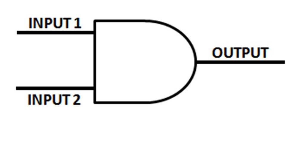
Figure 6-4. The AND Logic Gate circuit symbol
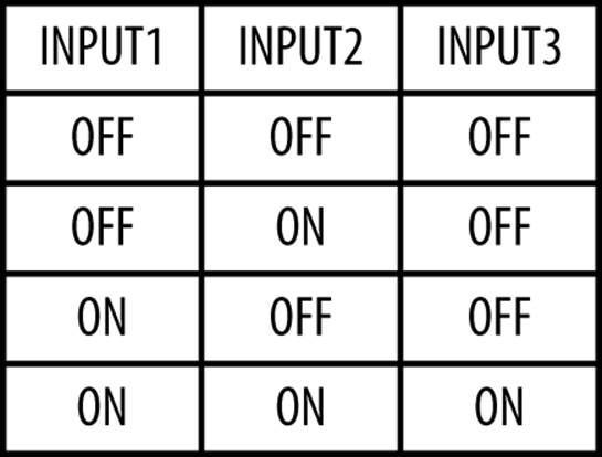
Figure 6-5. The AND Logic Gate truth table
WHY USE AN ARDUINO MICROCONTROLLER TO BUILD AN AND LOGIC GATE?
The AND Logic Gate is a simple electrical circuit where a string of pushbutton switches are wired in series. You can wire it up yourself right now, and get the same results without an Arduino. So the question “Why use an Arduino microcontroller to build an AND Logic Gate?” is very important.
The Arduino microcontroller, like all microcontrollers, has a bunch of programming instructions that are essentially built around logic operators (AND, exclusive OR [XOR], OR, and NOT [Complement(CPL)]). You can use these logic operators to make decisons based on the state of the pushbutton switches (open or closed) and using the appropriate logic operator. As you’ll see, you’ll actually be able to make the same circuit behave differently, simply by changing the Arduino code! Aren’t computers wonderful?
The Arduino AND Logic Gate
We’re going to replicate the AND gate using an Arduino. To make the circuit interesting, we’re going to use a photocell to replace one of the pushbutton switches from Figure 6-1. In Figure 6-6, we see the Arduino AND Logic Gate, with the LED turned off. Placing a piece of tape over the photocell (to allow no light into it, thus simulating nighttime) will make input pin D4 TRUE for the Arduino microcontroller. Pressing the pushbutton switch allows input pin D3 to become TRUE. With both inputs TRUE, the green LED turns on, as shown in Figure 6-7.
Figure 6-8 shows the Fritzing wiring diagram to use for building the Arduino AND Logic Gate. As shown in Figures 6-1, 6-7, and 6-8, you can build the Arduino AND Logic Gate on a MakerShield. The MakerShield makes the project portable so that you can carry it to show family and friends the basic logic gate used in computers, cell phones, robotics, and other smart electronic devices.
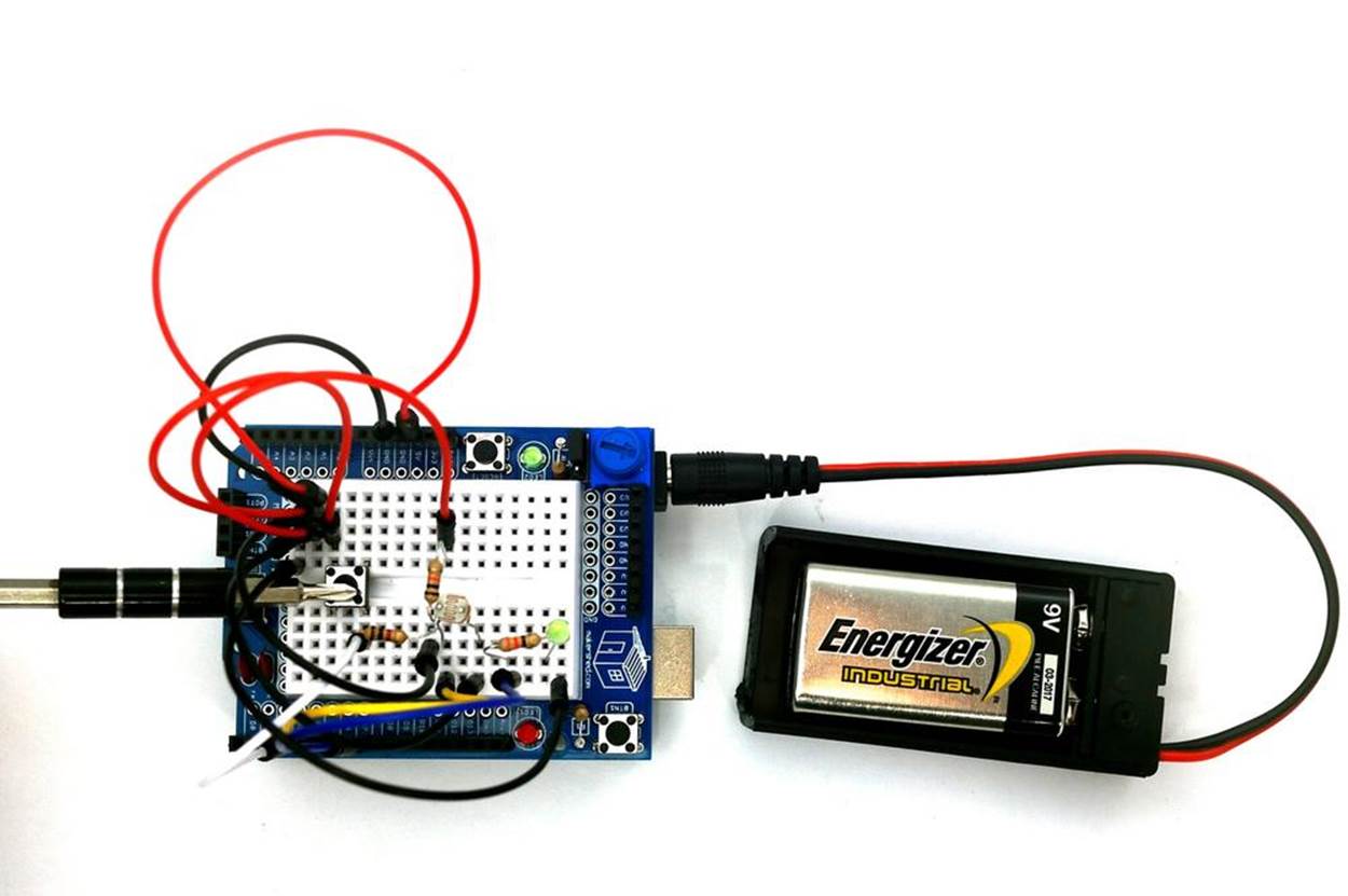
Figure 6-6. The Arduino AND Logic Gate with LED turned off
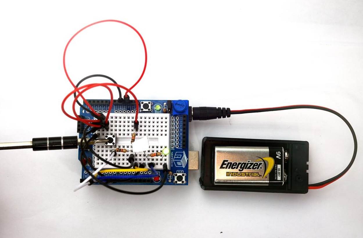
Figure 6-7. The Arduino AND Logic Gate with LED turned on
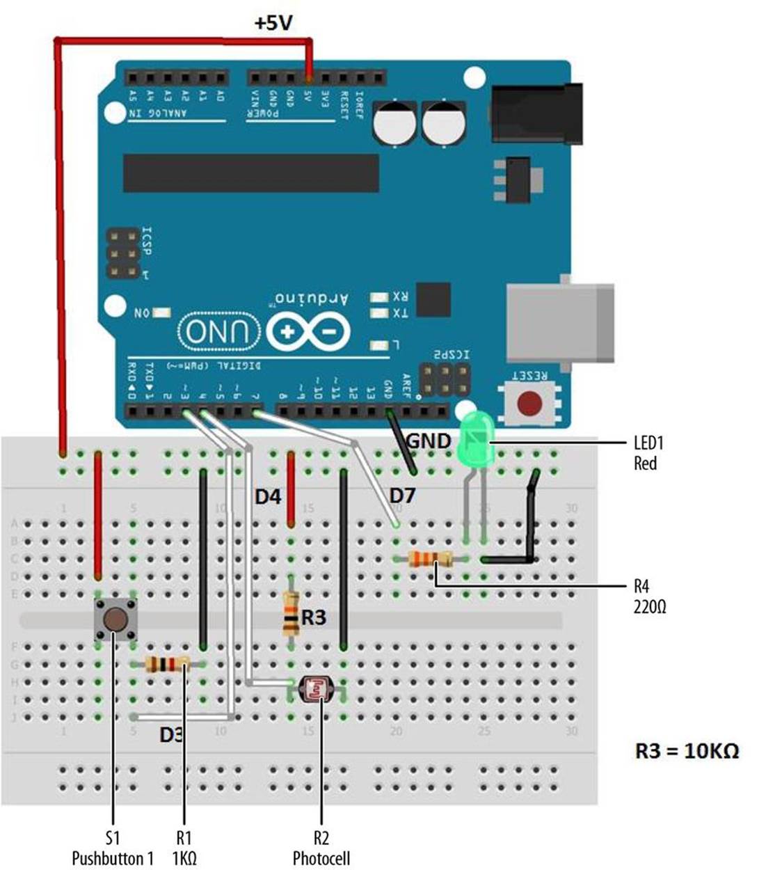
Figure 6-8. The Arduino AND Logic Gate Fritzing wiring diagram
TECH NOTE
The flat side of an LED is the negative pin.
Upload the Arduino AND Logic Gate Sketch
With the Arduino AND Logic Gate built on the MakerShield, it is time to upload the sketch. Example 6-1 operates the green LED using a pushbutton switch and a photocell. Here are the steps you’ll need to follow:
1. Attach the Arduino to your computer using a USB cable.
2. Open the Arduino software and type Example 6-1 into the software’s text editor.
3. Upload the sketch to the Arduino.
4. Press the mini pushbutton switch for a moment.
The Arduino AND Logic Gate will turn on the LED when the photocell is covered and the pushbutton switch is pressed. Releasing the pushbutton switch, or placing a light on the photocell, turns the LED off, because the AND condition (in which both switches are closed) no longer exists.
The Arduino does this by using the && operator in the if statement. && is the computer programming symbol for the logical AND function.
Example 6-1. The Arduino AND Logic Gate sketch
/*
The Arduino AND Logic Gate
Turns on an LED connected to digital
pin 7, when pressing a pushbutton switch and covering a photocell
attached to pins 3 and 4.
27 Jan 2013
Revised 4 September 2013
by Don Wilcher
*/
// constants won't change; they're used here to
// set pin numbers:
int B = 3; // the number of the B pushbutton pin
int A = 4; // the number of the A pushbutton pin
const int Cout = 7; // the number of the LED pin
// variables will change:
int AStatus = 0; // variable for reading the A pushbutton status
int BStatus = 0;
void setup() {
// initialize the LED pin as an output:
pinMode(Cout, OUTPUT);
// initialize the pushbutton pins as inputs:
pinMode(B, INPUT);
pinMode(A, INPUT);
}
void loop(){
// read the state of the pushbutton value:
AStatus = digitalRead(A);
BStatus = digitalRead(B);
// check if the pushbuttons are pressed
// if it is, the buttonStatus is HIGH:
if (AStatus == HIGH && BStatus ==HIGH) {
// turn LED on:
digitalWrite(Cout, HIGH);
}
else {
// turn LED off:
digitalWrite(Cout, LOW);
}
}
After uploading the Arduino AND Gate Logic sketch to the Arduino microcontroller, the green LED is turned off. As discussed earlier, pressing the pushbutton switch and covering the photocell will turn on the green LED. If either input device is FALSE (logic LOW), the LED turns off. To completely test the Arduino AND Logic Gate’s operation, remember to use the TT shown in Figure 6-5.
The block diagram in Figure 6-9 shows the building blocks and the electrical signal flow for the Arduino AND Logic Gate. Circuit schematic diagrams are used by electrical engineers to quickly build cool electronic devices. The equivalent circuit schematic diagram for the Arduino AND Logic Gate is shown in Figure 6-10.
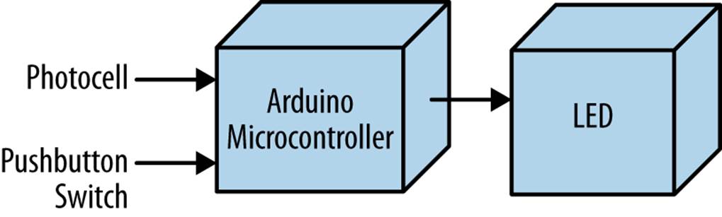
Figure 6-9. The Arduino AND Logic Gate block diagram
TROUBLESHOOTING TIP
If you don’t see the green LED turn on with the proper input logic, recheck the logic gate’s electrical wiring. Also, check to see if the green LED’s negative pin is wired to GND on the breadboard.
Something to Think About
How can the photocell be wired to analog A0 and be used as a digital input pin?
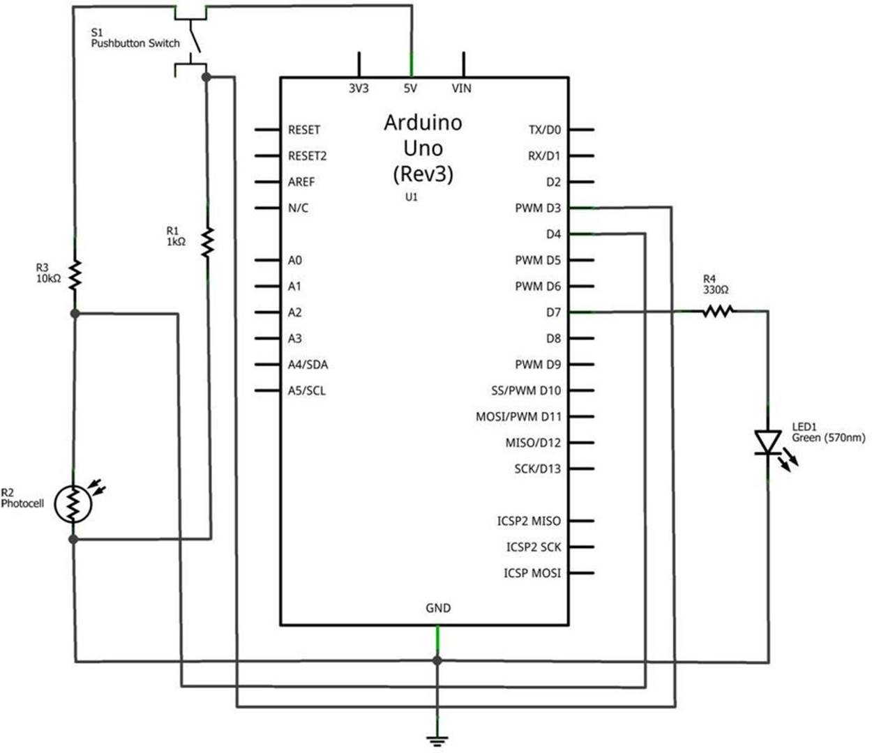
Figure 6-10. The Arduino AND Logic Gate circuit schematic diagram
All materials on the site are licensed Creative Commons Attribution-Sharealike 3.0 Unported CC BY-SA 3.0 & GNU Free Documentation License (GFDL)
If you are the copyright holder of any material contained on our site and intend to remove it, please contact our site administrator for approval.
© 2016-2026 All site design rights belong to S.Y.A.