Raspberry Pi Projects (2014)
Part III. Hardware Projects
Chapter 11. Disco Lightsby Mike Cook
In This Chapter
• Using individual bits in variables to define individual LEDs
• Connecting external LEDs to your PiFace board
• Writing a Python program user interface that looks like any windowed application
• Customising the user interface to use your own choice of colours
• Getting input from music
In my youth, during the late 60s, I answered an advertisement in the Manchester Evening News for someone to turn lights on and off in time to the music in an Ashton-under-Lyne night club. I went to the interview that Friday evening, which consisted of their showing me the lighting control rig and saying I had to be there by 7:30 p.m. on Saturday and Sunday. To be honest, I didn’t fancy five hours of switching lights on and off for just £1.00, so I arrived the following evening on my Lambretta with a rucksack full of electronics. I had a large multiway switch used in telephone exchanges called a uniselector (you can still get these on eBay), which was wired up to make an on/off control of five circuits. I started hacking the lighting panel, and before long, I had five coloured spotlights flashing away while I put my feet up.
These days, you cannot go hacking about with mains like that – health and safety would have a fit. And with the Raspberry Pi, you have the opportunity to do something a lot more sophisticated. So in this chapter, you are going to see how to control those disco lights, and change the pattern with a click of a mouse. Not only that, but you will see how to drive the light sequence from the beat of the music.
In this chapter, you’ll learn how to write a Python program to define a sequence of lights. You’ll also learn about various aspects of electronics and control.
Defining Your Sequence
So far in this book, you have written programs that interact through the Python console. Now you are going to produce a proper desktop application. This would be quite a daunting prospect if it were not for the help that you can get from a Python package that does a lot of the under-the-hood hard work for you. This just leaves you to specify exactly what things should look like. This package also integrates the windows style selected for your whole desktop, so the result looks consistent with other applications.
This package is called pygame and comes preloaded in most Raspberry Pi distributions. It consists of a number of functions to create and update windows, draw in the windows, register a mouse click and read the keyboard. It will also handle sound and music, but you will not be looking at that function this time.
Start IDLE, and select a new window. For a start let’s look at Listing 11.1, a very basic piece of code to open a window and close it down.
Listing 11.1 Windows1 Test Program
#!/usr/bin/env python
"""
Window1 to open up a window on the desktop
"""
import os, pygame, sys
pygame.init() # initialise graphics interface
os.environ['SDL_VIDEO_WINDOW_POS'] = 'center'
pygame.display.set_caption("Test Window 1")
screen = pygame.display.set_mode([788,250],0,32)
def main():
while True :
checkForEvent()
def terminate(): # close down the program
print ("Closing down please wait")
pygame.quit()
sys.exit()
def checkForEvent(): # see if we need to quit or
# look at the mouse
#print "checking for quit"
event = pygame.event.poll()
if event.type == pygame.QUIT :
terminate()
elif event.type == pygame.KEYDOWN and event.key == ![]()
pygame.K_ESCAPE :
terminate()
if __name__ == '__main__':
main()
When you run this, you should get just a black window in the middle of the screen. It won’t do much, but it is a real window. You can drag it around the screen, and clicking the minimise icon at the top-right corner will fold up the window and put it on the task bar at the bottom of the screen. Clicking the close cross will quit the program as will pressing the Esc key. When the program quits, you will get a message printed out in blue in the console window along with several lines of red debug information telling you where the program quit.
If you look at the anatomy of the program, you will see things are quite simple. The first few lines tell pygame to create a window, of a certain size, with a certain title and put it in the middle of the screen. The main part of the program is an infinite loop that constantly checks to see if an event has occurred.
In programming terms, an event is something happening, which is normally how user interaction gets input to the program. You are looking for a close event or a key up event on the Esc key. A close event is either the user clicking the close cross on the window or the operating system telling the program to quit because it is going to shut down. If your program sees any of those events, it calls a terminate function that prints out a message. Then it quits pygame to release any memory it grabbed, and it exits to the operating system.
Getting the Code to Do More
Well, that was not very exciting, was it? Let’s get the code to do a little more. Take a look at Listing 11.2.
Listing 11.2 Windows2 Test Program
#!/usr/bin/env python
"""
Window2 to open up a window on the desktop, draw something in it
and read the mouse position upon a click
"""
import piface.pfio as pfio # piface library
import os, pygame, sys
pygame.init() # initialise graphics interface
pfio.init() # initialise pfio
os.environ['SDL_VIDEO_WINDOW_POS'] = 'center'
pygame.display.set_caption("LED controll")
screen = pygame.display.set_mode([190,160],0,32)
box = False
def main():
drawBox(box)
while True :
checkForEvent()
def drawBox(state):
boxNum = 0
# first draw the box
# - fill colour depends on sequence bit state
if state :
pygame.draw.rect(screen,(255,0,0), ![]()
(50, 70, 40,40), 0)
else :
pygame.draw.rect(screen,(180,180,180),
(50, 70, 40,40), 0)
#now draw the outline of the box
pygame.draw.rect(screen,(0,0,180),(50, 70, 40,40), 3)
pygame.display.update() # refresh the screen
pfio.write_output(state)
def mouseGet() : # see where we have clicked
global box
x,y = pygame.mouse.get_pos()
print "The mouse has been clicked at ",x,y
if x in range(50,90) and y in range(50,110) :
box = not box # toggle the state of the box
drawBox(box)
def terminate(): # close down the program
print ("Closing down please wait")
pygame.quit()
sys.exit()
def checkForEvent(): # see if we need to quit
# or look at the mouse
#print "checking for quit"
event = pygame.event.poll()
if event.type == pygame.QUIT :
terminate()
elif event.type == pygame.MOUSEBUTTONDOWN :
mouseGet()
elif event.type == pygame.KEYDOWN and event.key == ![]()
pygame.K_ESCAPE :
terminate()
if __name__ == '__main__':
main()
When you run this, you will get a much smaller window on the desktop with a single square in it. Click in the square, and four things will happen. First the square will turn from grey to red, and then you will hear the relay on the PiFace board come on and see one of the LEDs come on. Finally you will see the position of the mouse when it was clicked printed out in window coordinates. That means that the coordinate value will be the same when clicking the same spot within the window, irrespective of where that window is positioned on the screen. Let’s see what’s been done here.
This time you add in the call to import the piface library, which is going to control the relay and lights. You set a variable called box to be false, which is called a logic or Boolean value and can only take on one of two values. You can call these values one and zero or true and false. The main function calls a drawBox function and then enters an endless loop that simply checks the events.
Take a closer look at the drawBox function. It takes in a variable, called state, that defines what colour the box is going to be. It is tested and you use the draw rectangle command from pygame. At first this looks complex, with lots of parameters or numbers in it, but it is quite simple. The first parameter in the command tells where you are going to draw the rectangle, in this case in an area called screen you defined at the start of the program. The next three numbers define the colour you will use in red, green and blue values – these are in brackets because they are one entity that could be replaced by a suitable variable later on called a tuple. Next you have four values bracketed as a tuple that define the X and Y coordinates of the rectangle, followed by how wide and how high to draw it. The final value tells the computer how wide a pen to draw this with. A zero is a special case and fills in the whole rectangle. Finally after drawing the rectangle, you have to tell the computer to update what is being shown on the screen.
This way of working means that no matter how complicated or time consuming it is to draw, the user always sees the screen change in a flash. The technical name for this is double buffering because one buffer, or area of memory, is being used to display the picture, and the other is being used to construct the next picture. The display update call copies the construction buffer into the display buffer. Note that at this point the display and construction buffers both contain the same thing. Finally in this function the variable state is written out to the PiFace board. As this Boolean variable can only be a zero or a one, then the least significant LED is turned on or off, and all the other LEDs are turned off.
The last thing to look at in this program is the mouseGet function, which is called by the checkForEvent function when it detects a mouse button down event. The mouseGet function first recovers the coordinates of the mouse pointer when it was clicked. Then the compound if statement checks if both the x and y fall within the coordinates of the box. If it does, then you toggle or invert the state of the variable box and then call the function that draws it and writes to the outputs.
So with a mouse click, you can control a light.
A Small Detour into Theory
Now you’ve got a program that doesn’t just act like a real window application; you can click in the window and control an output. However, before you can go on to looking at a complete sequencer you need to look a little bit about how the LEDs on the PiFace board are related to the value you write to the interface.
The basic unit of storage in a computer is the byte. A byte consists of eight bits, each bit being a separate logic level. Rather than think in bit terms, it is easier if you group these bits and consider storage in terms of bytes. However, as you will see you sometimes want to manipulate individual bits in that byte. In the last program you saw that a Boolean variable could only have one of two possible values; however it takes a byte to store that one variable, so all the other bits in it are wasted. If you take a byte, you can store the state of eight LEDs in it. The relationship between the byte, the bits and the LEDs is shown in Figure 11.1.
Figure 11-1: The relationship between bits and bytes.
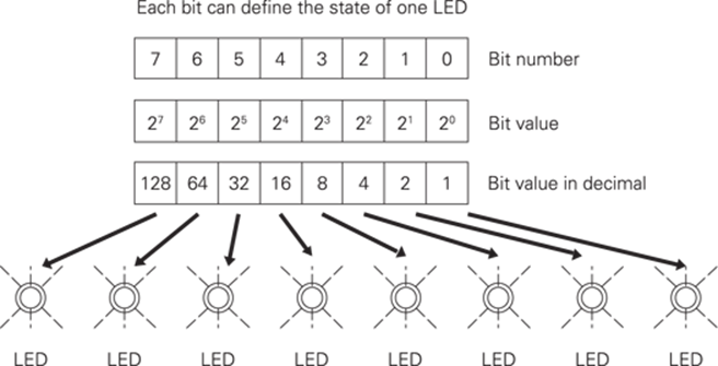
So by using a byte variable to store the state of all eight LEDs you can then use a list of these variable to store a sequence of LED patterns. To output each pattern all you have to do is to write out the next variable in the list to the PiFace board.
Designing the Sequencer
Now that you have all the elements in place you can begin to think about how you want this to look and operate. This is called top-down design because you start with a top-level view of what you want the software to look like.
I envisaged a grid of squares, each one representing an LED and its position in the sequence. A column of eight squares would represent the states of the LEDs at any instance in the sequence. A marker under the column will indicate what LEDs are being lit at any time. A mouse click in one of these squares will toggle the LED.
In order to help set up the sequence there should be some control buttons, one to clear or turn off all the LEDs in all sequence positions, and another to toggle or invert all the LEDs. There should be control buttons to determine the speed of the sequence and finally one to select where to take the trigger to advance the sequence from. This last point is important if you want to synchronise the changing of the lights to the beat of the music. The sequence can either be stepped at a regular rate determined by the speed controls, or locked into the beat of the music. This last feature will require a little bit of extra hardware and is optional – you can skip it for now and add it later if you like.
Finally it would be good if all the colours used in the sequence software were customisable; that is, it should be easy to change by changing a single value at one point of the code only. This means that whenever you use a colour you do not hard code it in by putting the colour numbers into a function call, but rather use a variable to define that colour. Those variables for all the colours should be grouped in one place in the code for easy access.
Implementing the Sequencer
After designing the sequencer from the top down, when it comes to implementing the design it is better to write the code in what is known as a bottom-up implementation. That means starting at the lowest possible function and working your way up. Of course, if you just look at the finished code, you don’t see that. I started by taking the window test program and writing the functions that showed the columns representing the LEDs in the sequence. Then I expanded it so that I could click on each LED to turn the box on or off. Next came the controls to clear and invert, followed by the step indicator. This was followed by the speed controls, and at this point I added the code to actually output something to the LEDs. Finally the auto/external step control was added and the code tidied up. This might not be the sequence of building up a program that first springs to the mind of a beginner, but the idea is to do a little coding and then test. So you are always looking to do something that can be instantly tested, even if it means writing the odd line of code that is not going to make it in the final mix. It also means that if something goes wrong with the test you know you have just written the code with the error in it.
Listing 11.3 shows the sequencer application.
Listing 11.3 The Sequencer Application
#!/usr/bin/env python
"""
Disco LED sequence display on the PiFace board
"""
import time # for delays
import piface.pfio as pfio # piface library
import os, pygame, sys
pfio.init() # initialise pfio
pygame.init() # initialise graphics interface
os.environ['SDL_VIDEO_WINDOW_POS'] = 'center'
pygame.display.set_caption("LED sequence controller")
screen = pygame.display.set_mode([788,250],0,32)
background = pygame.Surface((788,250))
# define the colours to use for the user interface
cBackground =(255,255,255)
cLEDon = (255,0,0)
cLEDoff = (128,128,128)
cOutline = (255,128,0)
cText = (0,0,0)
cTextBack = (220,220,220)
cStepBlock = (0,255,255)
background.fill(cBackground) # make background colour
font = pygame.font.Font(None, 28)
seq = [ 1 << (temp & 0x7) for temp in range (0,32)]
# initial sequence
timeInc = 0.3
stepInt = True # getting the step signal from inside the Pi
step = 0 # start point in sequence
nextTime = time.time()
lastSwitch = 0
def main():
setupScreen()
while True :
checkForEvent()
checkStep()
def checkStep() :
global step, nextTime, lastSwitch
if stepInt :
# if we are getting the step command from the internal timer
if time.time() > nextTime :
# is it time to do a next step
updateSeq(step)
step += 1
if step >31 :
step = 0
nextTime = time.time() + timeInc
else: # if not look at lowest switch
switchState = pfio.read_input() & 1
if switchState != lastSwitch and ![]()
lastSwitch == 0:
updateSeq(step)
step += 1
if step >31 :
step = 0
lastSwitch = switchState
def updateSeq(n) :
pygame.draw.rect(screen,cBackground, ![]()
(10, 202,768 ,10), 0) # blank out track
pygame.draw.rect(screen,cStepBlock, ![]()
(14 + n * 24, 202,10 ,10), 0) # draw new position
pygame.display.update()
pfio.write_output(seq[n])
def setupScreen() : # initialise the screen
screen.blit(background,[0,0]) # set background colour
drawControl(10,58,"Clear")
drawControl(86,62,"Invert")
drawControl(168,68,"Faster")
drawControl(250,74,"Slower")
drawControl(350,132,"Auto Step")
for x in range(0,32) :
drawCol(x,seq[x])
pygame.display.update()
def drawControl(xPos,xLen,name) :
pygame.draw.rect(screen,cTextBack, ![]()
(xPos, 216, xLen,32), 0)
pygame.draw.rect(screen,cOutline, ![]()
(xPos, 216, xLen,32), 2)
text = font.render(name, True, cText, cTextBack )
textRect = text.get_rect()
textRect.topleft = xPos+4, 220
screen.blit(text, textRect)
def drawCol(x,value):
boxNum = 0
x = 10 + x*24
y = 10
for bit in range(0,8):
# first draw the box –
# fill colour depends on sequence bit state
if ((value >> boxNum) & 1) != 1 :
pygame.draw.rect(screen,cLEDoff, ![]()
(x, y + 24*boxNum, 20,20), 0)
else :
pygame.draw.rect(screen,cLEDon, ![]()
(x, y + 24*boxNum, 20,20), 0)
#now draw the outline of the box
pygame.draw.rect(screen,cOutline, ![]()
(x, y + 24*boxNum, 20,20), 2)
boxNum +=1
def mouseGet() : # see where we have
# clicked and take the appropriate action
global timeInc, stepInt
x,y = pygame.mouse.get_pos()
if y in range(10, 202) and x in range(10, 778 ) :
bit = (y -10) / 24
byte = (x- 10) / 24
seq[byte] ^= 1 << bit
drawCol(byte,seq[byte])
pygame.display.update()
elif y in range(216,248) :
if x in range(10,58) : # the clear control
for a in range(0,32):
seq[a] = 0
drawCol(a,seq[a])
pygame.display.update()
if x in range(86,148) : # the invert control
for a in range(0,32):
seq[a] ^= 0xff
drawCol(a,seq[a])
pygame.display.update()
if x in range(168,236) : # the faster control
timeInc -= 0.05
if timeInc <= 0 :
timeInc = 0.05
if x in range(250,324) : # the slower control
timeInc += 0.05
if x in range(350,482) :
# the step source control
stepInt = not stepInt
if stepInt :
drawControl(350,132,![]()
"Auto Step")
else:
drawControl(350,132,![]()
"External Step")
pygame.display.update()
else:
#print "mouse ",x,y
def terminate(): # close down the program
print ("Closing down please wait")
pfio.deinit() # close the pfio
pygame.quit()
sys.exit()
def checkForEvent():
# see if we need to quit or look at the mouse
#print "checking for quit"
event = pygame.event.poll()
if event.type == pygame.QUIT :
terminate()
elif event.type == pygame.MOUSEBUTTONDOWN :
mouseGet()
elif event.type == pygame.KEYDOWN and ![]()
event.key == pygame.K_ESCAPE :
terminate()
if __name__ == '__main__':
main()
So let’s walk through the major sections of the code. It starts off by importing the required libraries and then initialising them and the program’s window. Next comes the section where you can customise the colours for the program. I found a black background looks best when you are using the program but a white background looks a lot better when viewed in a book. The next section defines the few global variables needed by the program.
The main function is simple, just four lines: Set up the screen, and then loop forever checking for events to quit or mouse clicks to change what is happening. Finally check if you need to advance the sequence. This sequence advance function follows next, although as you know, the order of the function definitions is not important.
The checkStep function first looks at the variable that defines where the trigger to the next step is coming from. If this is from the internal timer, the time now is compared to when the next step should occur, and if it is time, the updateSeq function is called, and the step variable is incremented and tested to see if it has not gone over the maximum number of steps. If it has then the step variable is reset to zero. This is known as wrapping around the counter. Finally the time for the next change is set up by adding the time now to the time increment variable. If the system is set up so that the sequence is advanced on a hardware input then that input is looked at to see if it is different from last time. This indicates a level change or an edge has been detected, and if the input level is now high, it is time to advance the sequence in the same way as before. One line that might puzzle beginners is this:
switchState = pfio.read_input() & 1
What the & operator does is to perform a bitwise AND operation between what is read and the number 1. The result of this is that the variable switchState just contains the least significant bit of the byte that is read from the PiFace board’s input lines. This means you can advance the sequence from the lowest switch or the music by attaching the special beat following circuit to it. I will describe that circuit later in this chapter.
The updateSeq function basically does two jobs; first it updates the position of the sequence indicator square by drawing a long thin rectangle in the background colour to erase the old square, and then drawing a new one. Finally it outputs the next pattern in the sequence with the following line:
pfio.write_output(seq[n])
This takes the list called seq and extracts the value that is next in the list given by the variable in the square braces and then writes it out to the PiFace board. This single line is what actually does the turning on and off of the lights; everything else just supports this one line.
The setUpScreen function simply calls other functions that draw the basic framework of the screen. So after wiping out everything in the screen buffer and setting it to the background colour there are five calls to draw control boxes. This call takes the parameters of the words in the box, its location in the x axis and the width of the box. Finally the drawCol, or draw column, function is called in a loop 32 times, one for each step in the sequencer. The two parameters it takes is what step in the sequence it is and what bit pattern it is to set it at.
Drawing text under the pygame module is a bit complex. First you have to define your font, which was done at the start of the code; the None parameter is the name of the default font file, and the number used is the font size. You then have to render the font into a bitmap, which is a little bit of a screen buffer that contains only the font characters you want. You then define a rectangle that encompasses the whole of this small bitmap. Then you have to position this rectangle to the correct part of the screen. Finally you transfer that small screen buffer to the main one with thescreen_blit call giving it the parameters of the screen buffer and where you want it put. See if you can follow those steps in the drawControl function.
The drawCol function draws a column of boxes, with one colour if that corresponds to a lit LED in the sequence or another colour if it is unlit. In order to do this you have to separate out all the bits from the sequence value. This is done by this line:
if ((value >> boxNum) & 1) != 1 :
What is happening here is that the variable called value is shifted to the left a number of times, defined by what box you are drawing. The AND operation then separates out just the least significant bit of this, as you saw before, and then makes the decision of what to draw based on this bit.
Finally the mouseGet function does all the work of dealing with clicks. First it gets the location of the mouse and checks to see if it is in the range of out array of LEDs in the sequence. If it is, it works out what byte or value this location represents in the sequence and what bit within that byte it is. Then this line toggles the bit:
seq[byte] ^= 1 << bit
It will look a bit odd and so calls for some explanation. The right side of the equals sign makes a number with a one in the bit position that you want to change. This is done by taking the value 1 and shifting it to the left the number of times you calculated when you worked out what bit was clicked. The equals sign is preceded by a caret symbol ^ and means the exclusive OR operation. So this number you have created by shifting is exclusive ORed with the value of the sequence at this point, and it is then put back into the sequence list. It is a shorthand way of saying this:
seq[byte] = seg[byte] ^ (1 << bit)
When you exclusive OR, or XOR as it is sometimes called, two numbers, the result is that you set bits that are only set to a logic one in one of the numbers and you invert the bits that are a set to a logic one in both numbers. So doing this operation simply inverts the bit corresponding to the bit you have clicked. You can then go and draw the whole column; again you update the screen image when you have finished all the drawing.
Next, the mouseGet function looks to see if the mouse has been clicked in any of the control boxes. If it has, it does the appropriate action. Clearing the sequence writes zero in every value in the sequence, while inverting applies an exclusive OR operation to all the bits in every value. The number 0xff is simply a byte with all bits set to one. This notation is called hexadecimal and believe it or not is simpler to think about than decimal when it comes to creating bit patterns. The faster and slower control boxes change the value to add to the nextTime variable. There are also some checks which stop the value from going below zero. Finally the last control changes the variable that determines where the sequence advance is coming from. In order to inform you where the advance trigger is coming from the text in this control box is changed when you click it.Figure 11.2 shows the sequencer as it appears on the screen.
Figure 11-2: The sequencer application.
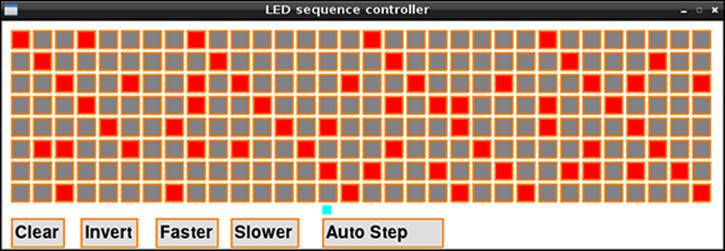
Notice the structure of the code. There is a data structure in a list called seq; it is the values in this list that control what is displayed on the screen, and what is output to the lights. Any changes are made to this list, and then the list is used to change the display as well as providing the output. Note that the screen display is not used to hold data – only reflect it. This is an important principle and is used whenever you try and write a nontrivial piece of code.
The Lights
The next step is to control some lights rather than the LEDs that are on the PiFace board. While these LEDs are good for testing they are not going to be very impressive in a disco.
The buffer on the PiFace board is capable of switching voltages up to 40V with currents up to half an amp. Now although it can do this on any output, it cannot do this on all the outputs at the same time. That is, there is a collective sum total of current the buffer can switch without getting too hot; this is about 650mA. This works out at about 80mA per output if you are to allow for all outputs to be on at once. What you are going to do is drive an LED strip off each output by using a 12V external power supply. There are two types of LED strips, those that have electronics embedded along the strip so that you can control individual lights in the strip, and those where the whole strip lights up at the same time when you apply voltage to it. You are going to use the latter type, which fortunately is cheaper as well.
These LED strips can be cut up at a point every third light, and every three lights consumes 20mA. Therefore you can tailor the amount of current drawn by simply cutting the appropriate length of strip. Some places sell these by the meter and others by the group of three. The absolutely cheapest place to get them is from the Far East through eBay, although the quality you get can be a bit hit and miss. There will be plenty of stockists that carry them in your home country.
In this project you have two options when it comes to powering these strips. The first is where the length of strip is restricted to 12 LEDs – that is about 130mm. The second is where you can power a strip length up to 0.7 of a meter, but more on that later. First you will look at the 130mm option.
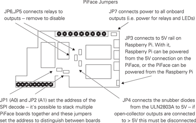
Before you start you will have to configure the PiFace board by removing some of the links. This involves removing jumpers JP4, JP5, JP6 and JP7; this disconnects the internal 5V supply from the PiFace board’s output devices and disables the relays. See Figure 11.3 for the position of these on the PiFace board. It is important you do this before connecting anything else up.
Figure 11-3: PiFace jumpers.
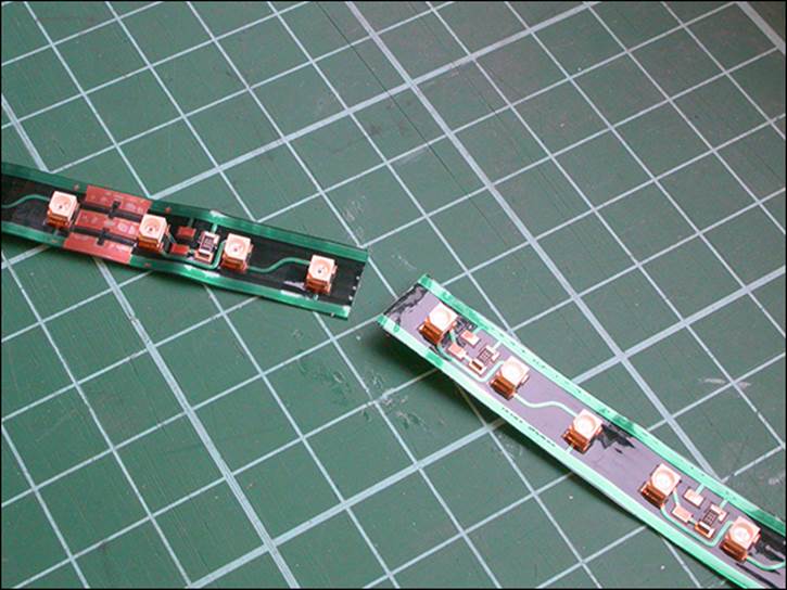
Now the LED strips come in different colours. Normally these are white, red, green, blue and amber, so no doubt you will be wanting some of each. You need to cut up each strip you want to light into smaller strips of 12 LEDs. Figure 11.4 shows you where to cut; you will need a sharp hobby knife or better still a scalpel. Every nine LEDs there is a copper soldering area; however this will not appear on the end of every strip of twelve lights. Not to worry – it is very easy to scrape the green solder mask off the board with a scalpel. If you don’t fancy that, you can always use the solder areas in the middle of the strips. You will end up with eight strips all the same length, but you might want a good mix of colours; the white ones do produce the most light however.
Figure 11-4: Where to cut the LED strip.
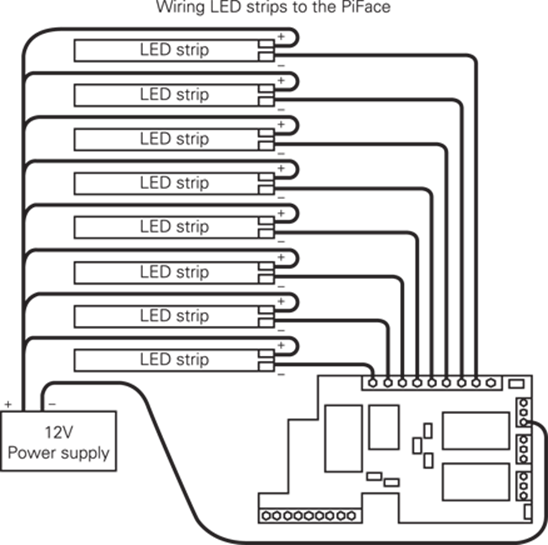
Then, you wire them up so that the positive for each strip is wired to the positive of your 12V power supply. The LED strips are marked with a + and - on the strips at every soldering area. The negative for each strip goes into a separate input of the PiFace board, and finally the right-most connector on the input strip is connected to the negative wire of your power supply. This is shown in Figure 11.5, and it is vital that you get the positive and negative wires from your power supply the right way around. Check this before wiring the strips to the PiFace board. When you have wired up the strip’s positive leads to the positive of the power supply, just take the negative lead from the strip and touch it against the negative lead of the power supply; if all is well the strip should light.
Now remove the power and touch the two negative wires again just to discharge the power supply before wiring it up to the PiFace board. Then attach the PiFace board to the Raspberry Pi and boot it up, plug in the 12V power supply and run the software. A note of caution: Never connect anything to the Raspberry Pi when it is powered up; it is easy to have an accident, and you can damage things with incomplete or partial wiring.
Figure 11-5: Wiring the LED strip to the PiFace board.
Using Longer Strip Lights
Now what about the longer strip light I mentioned at the start of the last section? You can draw up to 450mA from each of the outputs from the PiFace board so you can have longer strips of LEDs. This amount of current will drive 66 LEDs or 22 groups of three – this is a strip of 0.7 meters long. However, the down side is that you can’t have more than one LED strip lit at any one time. With the existing software it is too easy to make a mistake and set two or more LEDs to come on in each column, but with the changing of just one line in the code you can make the software act as a safety watch dog and only allow one strip light to be on at any one time. The line is in the mouseGet function six lines in, and it is one that has been discussed already:
seq[byte] ^= 1 << bit
Now take that line and change it to
seq[byte] = (seq[byte] & (1 << bit) ) ^ (1 << bit)
You might also want to change the title of the window and the colour scheme at the start so you can distinguish between the two programs. Also, save it under a different name. What this line now does is clear out the sequence value for all bits except the bit you have clicked, and then it toggles that bit. So if any other bit has been set in that step, it is cleared, and the bit you have clicked is toggled. This prevents you from setting more than one strip to be lit at any one time. However, there is still a slight danger because if you click the invert control, all the outputs but one will be on. To be on the safe side you should remove the following line (10 lines down from the one you just changed):
seq[a] ^= 0xff
To tidy up the screen display you should remove the call to drawControl that sets up the invert control in the setupScreen function. You don’t have to buy a strip 0.7 meter long; if you want, you can join strips together if you cannot buy them in the length you want.
Now all you need to do is mount your light strips in some way – maybe a display board above the decks, or hanging down from the ceiling. I mounted the eight strips on an 8 × 10-inch piece of MDF painted black. I arranged them in a fan shape over half a circle. This would stand up nicely under my monitor. The display is startlingly different depending on what you put in front of the LEDs. If you use nothing, they are very raw but do shed a lot of light. A thin styrene sheet of 0.5mm or less thickness acts as a good diffuser if placed close to the LEDs. However, if you set it just a few inches in front of them, the diffusion is much greater, and you no longer see the individual lights but bars of colour. Finally another good diffuser is a few layers of clear bubble wrap, the round bubbles in it nicely complementing the individual round LEDs. Your imagination, design skill and venue will allow you to put these strips, be they short or long, into many a pleasing configuration. However, if you want to cover the dance floor with them, you will have to install them behind acrylic sheets to prevent their being stamped on.
Making the Lights Move
Now so far you have looked at stepping the sequence along using the internal timers or an external push button, and if that is as far as you want to take this project, then fine. However, the next step is to have the music drive the change in sequence. Unfortunately this may not work as well as you might be expecting, but you can make a good stab at things relatively easily.
An audio signal, the sort that comes out of an MP3 player or from record decks, is a very complex waveform, consisting of lots of very rapid changes. The speed of the rapid changes carry the frequency content information of sound. The size of the waveform – that is, over what range of voltage values they cover – is the amplitude or loudness information. However, the amplitude is varying rapidly to convey the frequencies. What you need to do is to isolate the loudness factor – that is, to measure just the size of the peak of the waveform, but it is not quite as simple as that. With a loud sound you get a large positive value and a symmetrically large negative one, so in order to get a measure of loudness you have to ignore the negative value and hold the positive value at its peak. Such a circuit is possible and is called, rather unsurprisingly, a peak detector.
Now the beat of music is normally carried in the low frequencies. There are electronic circuits that will separate or filter a mishmash of frequencies so that only a specific range of frequencies get through. The two simplest type are known as high pass and low pass. In a low-pass filter only the low frequencies can pass through it. Exactly how low is low depends on what is known as the filter’s break frequency. This is defined as the frequency where the output is cut down by half compared with the input. By correct choice of components you can make this break frequency any value that you want. Most of the low frequencies in music are between 200Hz and 30Hz – any lower and you tend to feel it more than hear it. So to get at the beat of the music you must filter it with a low-pass filter at a break frequency of 200Hz. The key to filters is the capacitor component, which acts a bit like a frequency dependent resistor. The higher the frequency, the lower its resistance is to AC signals or its capacitive reactance.
The final piece in the jigsaw is called a comparator, which compares two voltages and gives a logic one output if one output is higher than the other or a logic zero if it is lower. By varying one voltage with a control knob or potentiometer and feeding a varying signal into the other, you can trigger a digital input when the varying voltage exceeds that set by the knob. If you feed the output of a peak detector into this you can, by turning the knob, set the level that will trigger the sequencer to advance to the next step.
Designing the Circuit
So to implement all that you need a couple of components called operational amplifiers, or op amps for short. These are very simple on the outside but quite complex on the inside. Basically there are two inputs marked + and – with a single output. The way it works is that the output is equal to the difference in voltage between the two inputs multiplied by a big number called the open loop gain, which is typically 100,000. So you might think that if you put one volt into the amplifier, you will get 100,000 volts out. Well, you would if you powered it with a 100,000 volt power supply and you could find an op amp that would work at that level. What happens in practice is that the output will only go as high as the power supply. Also the open loop gain is too high to be useful most of the time, and so when you design a circuit that you want to use as an amplifier some negative feedback is applied, as shown in Figure 11.6. Don’t confuse this with positive feedback, sometimes known just as feedback or howl around, when an amplifier’s output is fed into an input, like a microphone picking up the amplified sound.
Figure 11-6: A non-inverting amplifier.
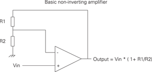
Negative feedback means feeding a proportion of the output back into the – (negative) input so that the input in effect gets turned down. Consider the circuit in Figure 11.6 and assume that there is zero volts on Vin, and also zero volts on the output. Also imagine that the two resistors have the same value. Now suddenly Vin is changed to 1V so the difference between the two inputs is also 1V. So the output sets off to amplify this difference into 100,000V. However, as the output rises to one volt then the voltage on the negative input will have risen to half a volt, because the two resistors act as a potential divider and feed half the voltage of the output back into the negative input. At this stage the difference between the two voltages is only half a volt, so the output tries to amplify this by 100,000 to give an output of 50,000V. But the higher the voltage gets on the output the more of it is fed back to the negative input. Eventually a balance point is reached when the voltage on the two inputs is exactly the same, and so the amplifier’s output will not get any higher. This balance point, in this case, happens when the output is exactly twice the input, so in effect the whole circuit has a gain of 2. You can make the gain anything you want, within reason, by simply altering the ratio of the two resistors. So if you feed a tenth of the output back into the negative input, you will have a gain of 10. The actual formula for calculating the gain is shown inFigure 11.6.
So armed with that information you can set about to design the beat extracting circuit whose schematic is shown in Figure 11.7.
Figure 11-7: The schematic of the beat driver.
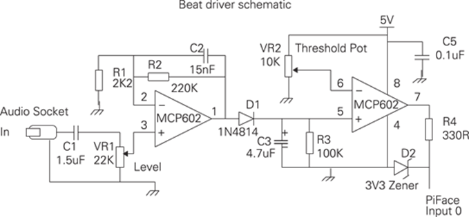
This uses two op amps which conveniently come in one package. The signal passes through C1 to remove any DC component and then into a pot so that you can set the level into the amplifier. This first op amp is configured just like the previous example as a non-inverting amplifier, only this time there is a capacitor across the feedback resistor. This means that for low frequencies the gain is determined by the value of resistor R2. But as the frequency increases, the capacitive reactance of the capacitor shorts out the feedback resistor to lower the gain. So in this section you have combined a low-pass filter with an amplifier.
The output of this amplifier is passed through a diode. This is a component that will only let electricity flow in one direction, in this case from the amplifier into capacitor C3. So as the waveform goes up and down rapidly it will start to charge up C3; it only gets more charge when the output of the first amplifier exceeds the voltage on C3 so this capacitor remembers the peak voltage of the audio signal. That is all well and good but you need some way of forgetting a peak signal that happened some time ago, and so R3 discharges the capacitor at a slower rate. The result is that the voltage on C3 represents the peaks of the signal or, as we say, it is an envelope follower. The value of R3 determines how quickly the envelope decays.
This envelope voltage is fed into the second op amp. Here you have no feedback, and you just use the open loop gain. The negative input is fed by a voltage set by a knob or pot VR2; this is a threshold voltage. If the envelope voltage is above this, then the output goes crashing up to the supply rail of 5V. If, however, the envelope voltage is below this threshold, then the output gets put firmly at zero volts or ground. This digital signal is too big to be fed into the PiFace board so it needs cutting down with R4 and D2 to make it a 3.3V signal suitable to dive the sequencer. D2 is a special sort of diode known as a zener diode; it starts to conduct at a set voltage. You can get these diodes that conduct at all sorts of voltages; you want one here to conduct at 3.3V or, as it is often written, 3V3. The ground is shown by the hatched symbol at the end of R1. All the points with this symbol must be connected together.
Building the Circuit
So what you need to do as the final step is construct this circuit. I much prefer making circuits on strip board and not solderless breadboard. The problem with breadboard is that it can make poor or intermittent contact which means that you could appear to have wired it up correctly but it is not. Therefore you can waste a lot of time just jiggling the components around hoping this will make it work. A small piece of veroboard or prototyping strip board is all you need. You can also use sockets for the integrated circuits, which means you can reuse them or replace them if they are damaged. The physical layout of the circuit is shown in Figure 11.8.
Figure 11-8: The physical layout of the beat driver circuit.
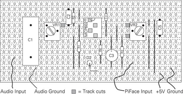
This shows the view of the board looking from the top or component side. The dotted lines indicate the copper strips on the underside of the board.
Running the Circuit
After you have built the circuit you need to attach it to your audio input and wire the output, 5V and ground into the PiFace board. Adjust the threshold knob until it is at the mid-point, and boot up your Raspberry Pi. Then run the sequence program and switch to the external step. Start off the music and adjust the volume until you start to see the sequence advance. If it won’t turn up far enough, you might have to increase the value of R2; try changing it to 470K. Then adjust the threshold until you see the sequence pick up the beat of the music. You might have to go back and adjust the volume. It works better on some types of music than others.
Over to You
Well, that comes to the end of my bit but not of your bit. You can extend and improve this in many ways. You can use transistors or FETs to drive longer LED strips and have many of them on all the time. You can extend the software to save your sequence in a file. Then make it so you can save different patterns in different files. You can implement a shift function where you can concatenate several sequences to make a much longer one and even display an extended sequence by drawing the new pattern when the old one is done. Better yet you could have the display scrolling. Or make the window bigger and the boxes smaller to fit more steps in.
You can add some software that keeps the sequence kicking over if you have switched to an external input and have not had a trigger for a certain amount of time. You could add a small delay after an external trigger to stop them from happening too rapidly. You can add an extra control button to set the sequence to a random pattern.
On the hardware side, you might have noticed that the dynamic range of some music makes it drop out of the trigger zone. There are special amplifiers called gated compressors; they are made so that things like walkie-talkies have a constant audio signal into the transmitter. The gain of the amplifier is adjusted automatically to keep the output constant. The SSM2165 is one example of such an amplifier.
You might want to replace the envelope follower’s discharge resistor with a pot, something like 220K. Finally you might want to adjust the filter capacitor, or even have a more sophisticated second or fourth order filter on the input. However, whatever you do, keep on dancing.
All materials on the site are licensed Creative Commons Attribution-Sharealike 3.0 Unported CC BY-SA 3.0 & GNU Free Documentation License (GFDL)
If you are the copyright holder of any material contained on our site and intend to remove it, please contact our site administrator for approval.
© 2016-2026 All site design rights belong to S.Y.A.