Raspberry Pi Projects (2014)
Part III. Hardware Projects
Chapter 15. Facebook-Enabled Roto-Sketchby Mike Cook
In This Chapter
• Learn about rotary shaft encoders
• Use rotary shaft encoders to control a drawing program
• See how to make Python draw a picture
• Discover how to interface to a tilt sensor
• Learn how to automatically load image files to Flickr and Facebook
Here is an idea I bet nobody has thought of before: Use two rotary controls to steer the path of a point on the screen. Where the point has been, it leaves a trail so you can sketch a picture using two knobs mounted on a box. In a crazy twist, how about if the picture was erased when you turned the box upside down and gave it a shake. Way out? I know, but it might just catch on, especially when you can post your artistic efforts straight to Facebook for all your friends to see.
The Concept
Well, maybe I have been beaten to a patent on this idea, but it is an interesting project from many angles – not the least of which is the requirement for a rotary control. In the old days of analogue, most rotary controls were potentiometers, or pots as they are called for short. These were potential dividers where a fixed resistance had a tap off point or wiper, controlled by a rotary knob or a slider control. The rotary type tended to have a travel of somewhere between 180 and 270 degrees; there were some special continuous rotary types, but they were made mainly for servo motor positioning control and were quite expensive. What is more, there was a dead spot where the wiper had to wrap round from one side of the fixed resistor to the other. An extra complication in using this sort of control with a computer is the fact that the pot produced a changing voltage output, and this has to be digitised with an analogue to digital converter (A/D) before a computer could make any use of it.
Although it is perfectly possible to build an A/D, it is often much simpler to keep everything in the digital domain. So, in modern designs where you want a continuously rotating control, a component is used called a rotary shaft encoder. These come in many different implementations, but by far the cheapest is the switched type. Another type is an optical encoder where the rotary movement is detected by something interrupting a beam of visible or infrared light. Optical encoders were widely used in the old type of computer mouse, the ones that had a ball in the base. A much newer type of rotary encoder utilises magnetic sensing to detect changes, which is covered in much more detail in the next chapter, “The Pendulum Pi, a Harmonograph”.
Rotary Encoder Types
The switched rotary encoder is at the heart of this project, and you have the choice of several different types. Perhaps the most distinguishing feature is whether the encoder has detents or not. A detent is a mechanical stop on a rotary spindle that divides the rotation into a set number of increments. When you twist an encoder with detents you feel multiple clicks as you twist. This is ideal for a control because you get a good positive feedback of its movement and when you release the control it stays where it is.
By far the most common type of encoder is known as the incremental type, which gives an indication of the fact that the control has been moved and in what direction it has been moved. Encoders are often classified by how many steps there are in one rotation. For switched encoders this is normally between 8 and 16 clicks per rotation. Some encoders also incorporate a central switch into the rotary control that is activated by pushing down. Applications for these types of controls include menu selection, volume control and switching through a large set of values. The point is that the controls themselves provide very little feedback on the exact angle they are at, leaving it to the application hardware and software to provide it in an appropriate manner.
The Encoder Output
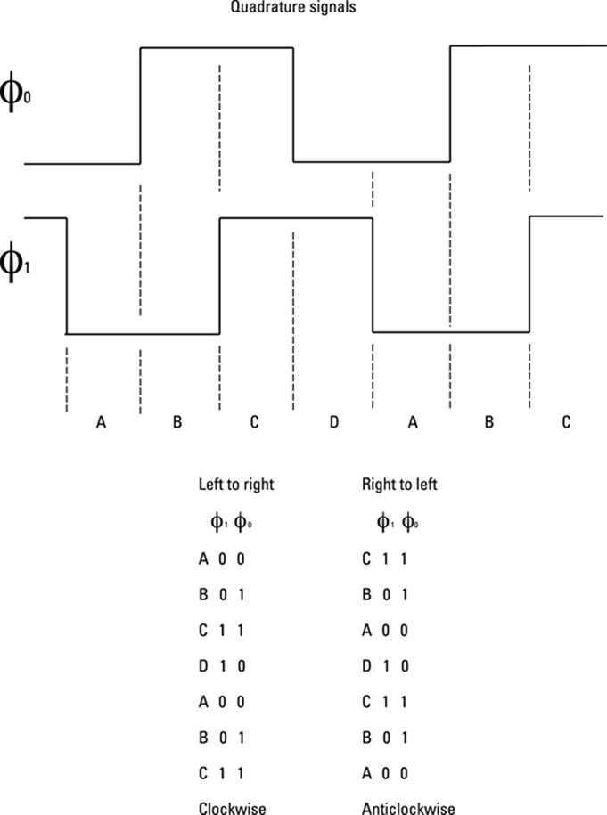
In order to use an encoder in any project you have to make sense of the signal it produces. There are two signal lines from each encoder and a common line. The signals are either connected to the common line or not by the internal switch, and normally the common line is connected to ground. The signals therefore are simply on and off, but they are phase shifted by 90 degrees from each other; the technical term for the signals is a quadrature output. Take a closer look at these in Figure 15.1. The two signals are normally called Ø0 and Ø1 although they are sometimes called A and B. This sort of diagram is called a timing diagram, time from left to right, logic level up and down. This shows what happens when you rotate the shaft clockwise. Looking at the two signals you will see there are four different combinations of high and low from the switch; each stable region between the transitions is marked with a letter on the diagram. One very important thing to notice is that only one of the outputs changes at any time; this sort of sequence is known as a Gray code after its inventor Frank Gray, and is used so there is never any confusion over what is being indicated, or if there is it is only between adjacent regions. Underneath the timing diagram is a list of each stable state of the output switches for clockwise and anticlockwise rotation. So you will see that you can’t tell very much from just looking at the outputs of the switch; you need to know a bit about the history – that is, what state they were in before.
This is all well and good but you have to take another thing into consideration, and that is contact bounce. When any mechanical contact makes or breaks it does not do it cleanly; that is, the transition from on to off is not a nice simple signal as is drawn on timing diagrams. Imagine dropping a table tennis ball onto a hard table; the ball doesn’t just hit the table and stop, but it bounces in a sequence of ever shorter bounces. The same thing happens to switches, and if the computer were to look at the switch often enough it would see a series of rapid on/off changes; this is known ascontact bounce and affects all mechanical switches to a greater or lesser extent. The duration of the bounces might be 20 to 200 mS or even longer in some cases. Most of the time this is not a problem because the rest of the code ensures that the switch is not looked at so frequently, but in some cases it is important, especially ones where the code is doing little between looking at a switch.
Figure 15-1: The logic output of a rotary encoder.
For example, imagine you just want to count how many times a button is pressed; simple code to do this will often fail due to contact bounce. It will appear to record more pushes than you make. The switch needs what is called debouncing, reminiscent of Tigger in Winnie the Pooh. For the simple example of just counting button pushes, a delay of 20 mS after a push is detected is normally enough to sort things out. However, contact bounce in rotary encoders can lead to problems of adding extra steps or getting the software monitoring it so mixed up that it thinks it is being turned in the opposite direction. As the shaft is sometimes being rotated quite rapidly, using a delay is inappropriate, so you have to consider something else to give a clean output. Fortunately the nature of the Gray code allows you to reject bounces.
For any given state of the outputs of a rotary encoder, there are three possible states it could change to next: one for clockwise rotation, one for anticlockwise rotation and one where it can’t possibly go but might due to contact bounce. This last state is an error state. Figure 15.2 summarises each current state of the encoder and the three states that could follow. So when you read an encoder, and knowing the last state, if you come across an error state then all you do is ignore the reading. That is, do not update the last state with the new reading and do not indicate a step movement. Otherwise you can indicate that a clockwise or anticlockwise motion has taken place and update the last state with the new reading.
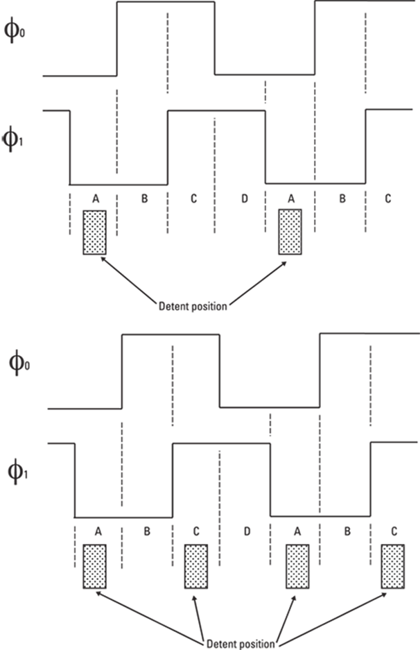
Well, you would think that covers it all, but there is one last curveball you have to cope with – and that is detents. There are two types of rotary shaft encoders with detents, and this is where the detents are placed in the switch output sequence. Figure 15.3 shows the two methods that are used. The first one has the detent in position A – that is, between the clicks the switch goes through all the transitions available. The order in which these transitions occur tells you if the click was a clockwise or anticlockwise click. The second scheme has a detent in every other position so it comes to rest with either both signals high or both low, but again the transition between these states tells you the direction. I have not seen an encoder with detents in every position, so, if they do exist, they are rare. Encoders made by the company Alps tend to have one detent per sequence, and those made by Bourns tend to have two. In this project I used Bourns encoders although it is simple enough to use Alps.
A rotary encoder needs quite a bit of looking after from the software point of view, and there are two ways to do this: with interrupts or polling. Interrupts are where the action of the switch causes the computer to interrupt what it is doing and call a special interrupt service routine which will handle the change. This is by far the best way of doing things, but unfortunately doing this under Linux is tricky and not very effective. It can be done but often the interrupts come too frequently for it to cope. The other way is polling, which is looking at the switches as quickly as possible in the code. This is an acceptable solution for this application as the code spends most of its time waiting for movement from the encoder and the visual feedback is such that a missing click or two during rapid rotation is not very important.
Figure 15-2: The logic sequence of the rotary encoder.
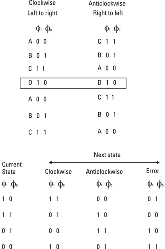
Figure 15-3: The two types of detents for rotary encoders.
Just one more thing you need to look at before you can start making your control box, and that is the detector that allows you to erase the drawing when you turn the control box upside down. For this the simplest thing to use is a tilt switch. In the old days this was made with mercury sloshing about in a tube that made an electrical contact with two wires mounted in the end of the tube. Now, however, the use of mercury is frowned upon, and it is even banned in certain classes of electronic equipment although you can still buy mercury tilt switches as a component. Although those are undoubtedly the best form of tilt switch, for this project a low-cost alternative will do quite nicely. This consists of a very small ball bearing sealed in a tube with contacts at one end; as the ball rolls to the end it shorts out the contacts. The problem with this sort of switch is that occasionally sometimes the ball fails to short out the contacts, but all that means in this context is that you need to shake it to bash the ball into the contacts.
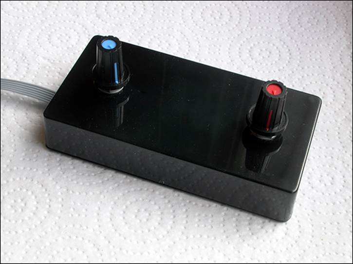
Now that you know about all the parts you need, it is time to put them together in a control box. Figure 15.4 shows the schematic of the control box. Basically the two encoders have three connections, and the centre is connected to ground as is one side of the tilt switch. Then all the other wires go to input pins on the PiFace board. Remember the inputs are numbers 0 to 7 – not 1 to 8. The encoders occupy the top four bits with the tilt switch being connected to the next one down, input 3. Note that inputs 2, 1 and 0 are not used in this project. I built this in a low-cost, ready-made black plastic box and wired it up with a length of ribbon cable stripped back to six connectors. I cut a small notch in the wall of the box to allow the ribbon cable to pass through when the lid was screwed on. This is shown in Figure 15.5. Finally the lid was screwed on and became the base of the unit, and four small self-adhesive feet of felt pads were attached and two knobs attached to the shafts. The final unit is shown in Figure 15.6.
Figure 15-4: The schematic for the roto-sketch control box.
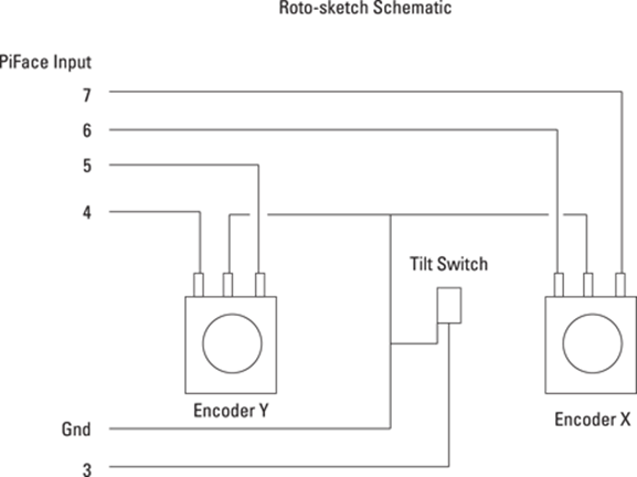
Figure 15-5: The wiring for the roto-sketch control box.
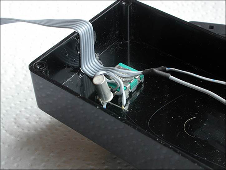
Figure 15-6: The finished roto-sketch control box!
It is time to test what you have; as usual, a short piece of code whose only function is to test the hardware is given in Listing 15.1.
Listing 15.1 Roto-Sketch Control Box Test 1
#!/usr/bin/env python
"""
Rotary Encoder input test 1 - raw inputs
encoders wired to inputs 6 & 7 and 4 & 5
"""
import piface.pfio as pfio # piface library
pfio.init() # initialise piface
print "Single encoder input test Ctrl C to quit"
print "Displays raw input from encoder"
lastEncoder = -1
display = ["00","01","10","11"]
while True:
encoder = pfio.read_input() & 0xF8
if lastEncoder != encoder:
enc2 = (encoder >> 4) & 0x03
enc1 = (encoder >> 6)
print display[enc1]," ",display[enc2],
if encoder & 0x08 != 0 :
print " box inverted"
else :
print " "
lastEncoder = encoder
You can see that this code is a bit fancy in the way it displays the input values. Rather than just have the raw number or even a bit pattern, I have used a list called display to show the bit pattern in a clear way. You can print it out in binary, but you get a 0b before the number, which makes it a bit difficult to read. As it is you will get the bit pattern printed out each time there is a change in the input. You can easily see what sort of detent encoder you have by noting the transitions between clicks. As the tilt switch is activated you will see a message telling you the box is inverted. The first pattern printed out is what you will be using for the X movement.
Next, you’ll try to do something with those numbers that are being returned. This is a bit more tricky than you might at first think. The program in Listing 15.2 takes just one of the encoders and keeps track of the clicks.
Listing 15.2 Rotary Encoder Testing
#!/usr/bin/env python
"""
Rotary Encoder input test 2 - show count
encoder wired to inputs 6 & 7
"""
import piface.pfio as pfio # piface library
pfio.init() # initialise piface
print "Single encoder input test Ctrl C to quit"
print "Displays accumulated count for X control"
lastEncoder = pfio.read_input() & 0xC0
count = 0
while True:
encoder = pfio.read_input() & 0xC0
if lastEncoder != encoder and (lastEncoder == 0 or ![]()
lastEncoder == 0xC0):
if (lastEncoder == 0 and encoder == 0x80) or ![]()
(lastEncoder == 0xC0 and encoder == 0x40) :
count -=1
if (lastEncoder == 0xC0 and encoder == 0x80) or ![]()
(lastEncoder == 0 and encoder == 0x40) :
count +=1
print count
lastEncoder = encoder
When you study the listing you will see that what happens here is that once the encoder is read, the values are passed into an if statement that looks for the condition of the last encoder reading being in one of the two detent positions, and the current reading not being the same as the last reading. In other words the encoder has just moved from its rest position. Now you see in what direction it has turned by looking at the current reading in conjunction with the last reading. There are two possible readings for an anticlockwise motion depending on the previous reading; if either of these two conditions is met then a count is decremented. Similarly for a clockwise movement there are two possible previous and current combinations indicating a click. Notice that the position is printed out independently of either clockwise or anticlockwise rotation being detected. This means that if you see two numbers the same printed out consecutively, then there has been a contact bounce reading that has resulted in an error which has been ignored. You will notice that the values compared with those from the encoder are hard coded. That is, they refer only to that one encoder wired in the top two bits of the input. In order to make things more efficient you can shift the bits you are interested in into the lowest two bits and use the same code for reading both encoders.
Posting to Facebook
Now you want to be able to post your creations to Facebook, and it is not as easy as you might think. This part has perhaps taken up more hours to get right than anything else in this book. Facebook does allow picture posting to happen remotely, but you have to register with them as a developer and you have to have a server that will run your app. Although this is fine for purveyors of mobile apps and the like, it has a few downsides for the individual. You end up needing to pay for the app hosting and creating a unique name for yourself. Also, the fact that you need to create the app in another language is offputting for beginners. It also would not be good for Facebook to have all of you readers create your own apps just for your own personal use. All in all this is much more complicated than it should be.
Using Flickr
Whereas Facebook is difficult to post to, Flickr makes it some what easier to upload pictures and, as an added bonus, you can link your Flickr account to Facebook – so two for the price of one. However, it is not all plain sailing, and it is not as simple as it could be. One way to post a picture is to e-mail your pictures to Flickr, to a unique address you can find on your Settings page. This is easy to automate, but unfortunately pictures posted like this never seem to be transferred onto your Facebook timeline. This problem stumped not only the online forum of experts but also Flickr’s help desk. It turns out that this is actually a bug in the Flickr web code which might be fixed by the time you read this, but I can’t rely on that when writing a book – it has to work now.
Pictures posted from a browser however are linked to Facebook, so what is required is to have some way of doing that automatically from the Pi. The answer I came up with was to use the folders2flickr package found athttp://code.google.com/p/folders2flickr/source/checkout, which is actually a subversion repository for the code. Subversion is a revision control software system that is used in professional circles; it keeps track of developers working on a small subset of files for a large project. It maintains a backup system so that any earlier version of code can be reverted to at any time. This is very handy because a common occurrence, when many developers are working on a large program, is that someone will make a change that will break the code in an area he or she is not working on, and therefore will not see. Subversion allows the developers to rapidly backtrack and revert to a previously working project. To get at the source code for the folders2flickr package, all you need to do is to use the desktop to go to the directory that you are working with for this chapter; I suggest you name it sketch as it will eventually contain the code to drive the roto-sketch hardware. Then from the Tools menu select the Open Current Directory in Terminal option. This will cause a Terminal window to appear. Type this into it:
svn checkout http://folders2flickr.googlecode.com/svn/trunk/
folders2flickr-read-only
Type the preceding all on one line, and it will download a zip file of the package’s source code. Then type
unzip folders2flickr-read-only
to unzip the source code files. Then go back to the desktop and change the name of the resulting directory to just folders2flickr. Now you have to edit a file in this directory called uploadr.ini so that it works the way you need it to. Double-click it to open up a text editor and change the line
imagedir=d:\pictures
to read
imagedir=roto-sketch
This sets the directory that contains the files to be uploaded to Flickr. Then edit the visibility parameters to read
public = 1
friend = 0
family = 0
This is needed because only publicly visible files are passed on to Facebook, never family or friends. Save this file in your sketch directory – not in the folders2flickr directory where it came from. At this stage it is best if you authenticate the package with your Flickr account, so make sure that you have a directory called roto-sketch in your sketch directory and that it contains a small image. Now make sure that you are connected to the Internet, get a command line in the sketch directory and then run the package by typing
python folders2flickr/uploadr.py
It is important you do this and not get your command line in the folders2flickr directory because this package has a bit of an issue with where it puts things and doing it this way will make it work when you get to running the final program. However, this is where things could get tricky because you will be asked if you have authenticated this program yet. Whatever you do at this stage do not answer this question yet. What will happen is that a browser window will pop up. I say “pop”, but this rather exaggerates the speed; it will rather ooze up as opposed to pop. When I tried this, the browser Dillo popped up and then refused to do anything. I had to arrange for the browser Midori to pop up instead by deleting the Dillo browser. When it does you wait and wait, until the window opens and the Flickr login page appears. Even then you have to wait for something to finish. The trick is to keep an eye on the CPU usage block in the bottom right-hand corner; when this stops showing solid green you can then type your username and password and log in. Two more pages will follow asking you if it is correct that you want to authorise the use of this package. Only when the page telling you to close the page has finished loading and you have closed the page can you then go and answer that question on the Python console with an affirmative Y for yes. Then the contents of your roto-sketch directory will be transferred to Flickr.
When you look at your sketch folder after this you will see that there have been some files created by this process – an error log, a debug log and a file called history. This history file is used to make sure only images that were placed in the roto-sketch directory since the last upload are uploaded and not all of them again. If you turn on the Show Hidden option in the View menu you will also see a file called .flickrToken; this information is used so that you don’t have to go through the authorisation process each time you run the uploader. If you are curious, you can double-click the file and see what the token looks like. However don’t alter it or delete the file, or you will have to go through the whole authorisation rigmarole again. You should now go to Flickr and check that the image has arrived. At the same time you can go to the Settings page and click the option to connect Flickr to Facebook. You will then have to go to Facebook and set the permissions as to whom you want to see these postings from Yahoo!. (By default it is just you.) This is found in the App Center icon on the left side; click Your Apps, and use the Yahoo one. Click Yahoo to change the settings.
![]()
A word of caution: It can take up to an hour after posting on Flickr for the pictures to appear on Facebook. If they still don’t appear, Flickr recommends disconnecting the Facebook link, waiting a few minutes and then connecting it again. I have had to do this once.
Part of the problem I found with the setup was the poor wording of the instructions that were printed out during the authorisation phase. I think it would be much better if the getAuthKey function, in the uploadr.py file, were replaced by the code in Listing 15.3.
Listing 15.3 Replacement getAuthKey Function
"""
Checks to see if the user has authenticated this application
"""
def getAuthKey( self ):
d = {
api.frob : FLICKR[ api.frob ],
api.perms : "delete"
}
sig = self.signCall( d )
url = self.urlGen( api.auth, d, sig )
ans = ""
try:
webbrowser.open( url )
print "You need to allow this program to access ![]()
your Flickr site."
print "A web browser should pop open with instructions."
print "When you have authenticated this application ![]()
type Y"
print "If you failed or don't want to then type N"
ans = raw_input("Sucess? (Y/N): ")
except:
print str(sys.exc_info())
if ( ans.lower() == "n" ):
print "Please try again"
sys.exit()
The action of the function is the same, but the user instructions are much more clear.
The Final Roto-Sketch Program
With all the pieces of infrastructure in place you now come to the final program which brings this all together. The Roto-Sketch program is shown in Listing 15.4.
Listing 15.4 The Roto-Sketch Program
#!/usr/bin/env python
"""
Rotary Encoder Roto-sketch
encoder 1 wired to inputs 6 & 7
encoder 2 wired to inputs 4 & 5
Tilt switch wired to input 3
"""
import colorsys
from smbus import SMBus
import os, sys, pygame
from pygame.locals import *
import piface.pfio as pfio # piface library
import subprocess
pfio.init() # initialise piface
pygame.init() # initialise pygame
pygame.event.set_allowed(None)
pygame.event.set_allowed([pygame.KEYDOWN, pygame.QUIT,![]()
pygame.MOUSEBUTTONDOWN])
os.environ['SDL_VIDEO_WINDOW_POS'] = 'center'
pygame.display.set_caption("Roto-Sketch")
screen = pygame.display.set_mode([512,512],0,32)
lastEncoder = [0,0]
current_reading = [256,256]
last_reading = [256,256,256,256]
# defines initial starting position
col = (0,0,0)
colCursor = (128,128,128)
background = (255, 255, 255) # screen background colour
picture = 1 # picture number
fileName ="name"
lastPort = -1
def main():
global current_reading, last_reading
print "Roto-sketch the keys are:-"
print "R, G, B, Y, M, P, K (black), W to select colour"
print "Space bar for wipe screen"
print "L - for Line to saved point, C for Circle centre on ![]()
save point"
print "S to save current point for future line and ![]()
circle commands"
print "Home key to save sketch to file"
print "# to post on Flickr and Facebook"
blank_screen()
while(True): # do forever
readEncoders()
pygame.draw.rect(screen,col,(last_reading[0],![]()
last_reading[1],2,2),0)
pygame.draw.line(screen,col,(last_reading[0],![]()
last_reading[1]),(current_reading[0],current_reading[1]),2)
pygame.draw.rect(screen,colCursor,(current_reading[0],![]()
current_reading[1],2,2),0)
last_reading[0] = current_reading[0]
# save this position for drawing from for next time
last_reading[1] = current_reading[1]
pygame.display.update()
#end of main loop
# Function definitions
# read two encoder with alternating 00 11 detent
def readEncoders() : #exit when one has moved
global current_reading, lastPort
moved = False
inc = 8
while not moved :
checkForQuit()
port = pfio.read_input()
portP = (port & 0xc0) >> 6
lastPortP = (lastPort & 0xc0) >> 6
for axis in range(0,2) :
if lastPortP != portP and (lastPortP == 0 or ![]()
lastPortP == 0x3) :
if (lastPortP == 0 and portP == 0x2) or ![]()
(lastPortP == 0x3 and portP == 0x1):
current_reading[axis] -= inc
moved = True
if (lastPortP == 0x3 and portP == 0x2) or ![]()
(lastPortP == 0 and portP == 0x1):
current_reading[axis] += inc
moved = True
portP = (port & 0x30) >> 4
lastPortP = (lastPort &0x30) >> 4
if port &0x8 :
blank_screen()
lastPort = port
def blank_screen():
screen.fill(background) # blank screen
pygame.display.update()
def terminate():
print "Closing down please wait"
pfio.deinit()
pygame.quit()
sys.exit()
def checkForQuit():
global col, picture, last_reading, fileName
event = pygame.event.poll()
if event.type == pygame.QUIT :
terminate()
elif event.type == pygame.KEYDOWN :
# get a key and do something
if event.key == pygame.K_ESCAPE :
terminate()
if event.key == K_SPACE or event.key == K_DELETE:
blank_screen()
if event.key == K_r : # draw in red
col = (255, 0, 0)
if event.key == K_g : # draw in green
col = (0, 255, 0)
if event.key == K_b : # draw in blue
col = (0, 0, 255)
if event.key == K_y : # draw in yellow
col = (255, 255, 0)
if event.key == K_m : # draw in magenta
col = (255, 0, 255)
if event.key == K_p : # draw in peacock blue
col = (0, 255, 255)
if event.key == K_w : # draw in white
col = (255, 255, 255)
if event.key == K_k : # draw in blacK
col = (0, 0, 0)
if event.key == K_s : # save current point
last_reading[2] = last_reading[0] # save X
last_reading[3] = last_reading[1] # save Y
if event.key == K_l : # draw a line to saved point
pygame.draw.line(screen,col,(last_reading[2],![]()
last_reading[3]),(last_reading[0],last_reading[1]),2)
pygame.display.update()
if event.key == K_c : # draw a circle
try :
r = ((last_reading[0] - last_reading[2])**2 ![]()
+ (last_reading[1] - last_reading[3])**2 ) ** (0.5)
pygame.draw.circle(screen,col,![]()
(last_reading[0],last_reading[1]),int(r),2)
pygame.display.update()
except:
pass
if event.key == K_HASH :
#Save folder to Flickr / Facebook
print "sending folder to Flickr"
subprocess.check_output("python ![]()
folders2flickr/uploadr.py",shell=True)
print "done"
if event.key == K_HOME : # save a picture
print "save sketch to file"
if picture == 1 : # first time to save this session
fileName = raw_input("Enter file name ![]()
for this session ")
try:
pygame.image.save(screen,![]()
'roto-sketch/'+fileName+str(picture)+'.png')
except:
os.system('mkdir roto-sketch')
pygame.image.save(screen,![]()
'roto-sketch/'+fileName+str(picture)+'.png')
print "saving sketch as ",![]()
'roto-sketch/'+fileName+str(picture)+'.png'
picture +=1;
if __name__ == '__main__':
main()
It is possible that you could get an error on the line
from smbus import SMBus
If you do then you will need to install smbus, which is easily done by typing
apt-get install python-smbus
on a command line.
The code might look complex, but it consists of a few simple functions – some of which you have already looked at when you considered the rotary controls. It starts off in the normal fashion by importing the modules it will need, and setting up some global variables. Then it prints out some simple user instructions about the keys. Basically there are a group of keys that will change the colour of the drawing track, a key to wipe the screen in case you have not got a tilt switch fitted, some keys that control what is drawn and finally two keys to save the images and post them to Flickr – and hence to Facebook.
The main function after the instructions are printed out is a simple endless loop of reading the encoders and then drawing the lines when that function returns with an updated reading. The readEncoders function is basically what is in Listing 15.2 only for two encoders. It keeps looking at the input port and makes the decisions based on what it sees. This function can do this for both encoders by using a for loop and shifting the reading for the X encoder into the least two significant bits and then shifting the Y encoder into the least significant bit for the second trip through the loop. When a movement is detected the logic variable move is set to true and the function returns to do the plotting on the screen. The tilt switch is also monitored, and the screen is wiped if it is found to be upside down. The increment value is set at 8; that is, it moves 8 screen pixels per click, but you can make it a smaller value if you want finer control over the movement of the plotting point. When this function returns, the values in the current reading list have been updated, and the program draws a line between the current point and the last point. The current point is replaced with a grey square to allow you to see where you are, in the same way that mechanical versions of this program had a current point that you could just see. This allows you, in theory at least, to retrace over a line to start off somewhere new. So before the program draws a line this cursor square has to be erased and put back in the new position after the line is drawn. That is why there are three drawing commands where you might be expecting only one. The current readings are copied into last-reading variables before the screen is updated.
The checkForQuit function looks at not only quit events but also key events. These drive the settings of the program. For example, the current drawing colour can be changed by pressing a key; all the primary and secondary colours are available as well as black and white. Note that for black you have to press the K key because the B key is already taken with switching to blue. The spacebar or Delete key simply calls the blank_screen function.
The later part of the checkForQuit function performs the neat special effects of the program. First the L key will draw a line between the current point and a previously saved point. Next the C key will draw a circle centred on the current point with a radius given by the distance to the saved point. Finally the S key will save the current point as the set point for those two previous commands. The circle drawing has to be in a try structure to prevent the program from crashing when the current point is the same as the saved point. These circles and lines give the drawings a lot more interest than the random scribblings that is often made with these sorts of toys.
The saving and transfer keys are the Home key and the hash key. The Home key saves the current screen into the roto-sketch folder as a PNG picture file. When you press this for the first time after the program starts you are asked for a name to prefix the picture file. You have to click the Python shell console window to give it the focus and type in a name. The program will then use that name for all subsequent screen saves and append a number on the end of each new file. After you have entered the name, you should click back on the sketch window so that it can process subsequent keys. If there is not a roto-sketch directory, one will be created. Now when you press the Home key again, the filename is printed out, but there is no need to enter anything; it uses the name you gave it last time plus an incrementing number. The hash key (#) transfers the new images in the roto-sketch folder out to Flickr, which can take from 10 seconds to just over a minute depending on the state of your Internet connection and traffic at the Flickr site.
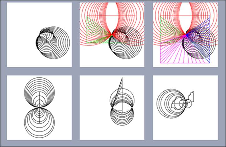
Many interesting patterns can be drawn with this machine, a few of which are shown in Figure 15.7. You can save the pattern as you go, seeing it get increasingly complex.
Figure 15-7: Some of the pattern effects you can achieve.
Creating a Symmetrical Pattern
Consider one extra variant – symmetry. The output can be made more interesting by the use of reflections to generate a symmetrical pattern rather like a kaleidoscope. There are two ways you can do this: The first is by rotation of the points used to draw the pattern, and the second is by copying what is actually drawn and placing it in several places on the screen. At first this might sound like it would produce the same results – and it does for a limited amount of drawing – but the results of the two can look very different. This is because if you draw on a small segment and your drawing extends outside the bounds of the segment, you will not see any lines. However, if you are rotating the drawing points, then drawing outside the segment will be seen in the other segments. This fundamentally changes how things look with regard to reflections. Rotation of a point is easy; you just have to apply the following formula to the X and Y coordinates of the point to get the new point X' and Y':
X' = X Cos θ - Y Sin θ
Y' = X Sin θ + Y Cos θ
θ is the angle of rotation about the origin. So to get the origin in the centre of the screen, you have to subtract half the width from the reading values. You can use a loop to repeatedly do this for as much repeating as you want. I will leave that with you to do as an exercise. What I will give you here is an example of the second, more interesting, reflection kaleidoscope-style of symmetry. This plots the picture into an off-screen buffer, and then makes up the screen by repeating this buffer in a reflected and inverted manner to give a four-fold symmetrical pattern. This new variant is shown in Listing 15.5.
Listing 15.5 Kilido-Sketch
#!/usr/bin/env python
"""
Rotary Encoder Kilido-sketch
Four fold symmetry
encoder 1 wired to inputs 6 & 7
encoder 2 wired to inputs 4 & 5
Tilt switch wired to input 3
"""
import colorsys
from smbus import SMBus
import os, sys, pygame
from pygame.locals import *
import piface.pfio as pfio # piface library
import subprocess
pfio.init() # initialise piface
pygame.init() # initialise pygame
pygame.event.set_allowed(None)
pygame.event.set_allowed([pygame.KEYDOWN, pygame.QUIT, ![]()
pygame.MOUSEBUTTONDOWN])
os.environ['SDL_VIDEO_WINDOW_POS'] = 'center'
pygame.display.set_caption("Klido-Sketch")
segSize = 350
screen = pygame.display.set_mode([segSize*2,segSize*2],0,32)
segment = pygame.Surface((segSize,segSize))
lastEncoder = [0,0]
current_reading = [128,128]
last_reading = [128,128,128,128]
# defines initial starting position
col = (0,0,0)
colCursor = (128,128,128)
background = (255, 255, 255) # screen background colour
picture = 1 # picture number
fileName ="name"
lastPort = -1
def main():
global current_reading, last_reading
print "Kilido-sketch the keys are:-"
print "R, G, B, Y, M, P, K (black), W to select colour"
print "Space bar for wipe screen"
print "L - for Line to saved point, C for Circle centre on ![]()
save point"
print "S to save current point for future line and ![]()
circle commands"
print "Home key to save sketch to file"
print "# to post on Flickr and Facebook"
blank_screen()
while(True): # do forever
readEncoders()
pygame.draw.rect(segment,col,(last_reading[0],![]()
last_reading[1],2,2),0)
pygame.draw.line(segment,col,(last_reading[0],![]()
last_reading[1]),(current_reading[0],current_reading[1]),2)
pygame.draw.rect(segment,colCursor, ![]()
(current_reading[0],current_reading[1],2,2),0)
last_reading[0] = current_reading[0]
# save this position for drawing from for next time
last_reading[1] = current_reading[1]
screenUpdate()
def screenUpdate():
segRect = pygame.Surface.get_rect(segment)
screen.blit(segment, segRect)
segRect.topleft = segSize,0
screen.blit(pygame.transform.flip(segment, True, ![]()
False), segRect)
segRect.topleft = 0,segSize
screen.blit(pygame.transform.flip(segment, False, ![]()
True), segRect)
segRect.topleft = segSize,segSize
screen.blit(pygame.transform.flip(segment, True, ![]()
True), segRect)
pygame.display.update()
#end of main loop
# Function definitions
# read two encoder with alternating 00 11 detent
def readEncoders() : #exit when one has moved
global current_reading, lastPort
moved = False
inc = 6
while not moved :
checkForQuit()
port = pfio.read_input()
portP = (port & 0xc0) >> 6
lastPortP = (lastPort & 0xc0) >> 6
for axis in range(0,2) :
if lastPortP != portP and (lastPortP == 0 or ![]()
lastPortP == 0x3) :
if (lastPortP == 0 and portP == 0x2) or ![]()
(lastPortP == 0x3 and portP == 0x1):
current_reading[axis] -= inc
if current_reading[axis] < 0:
# restrain to segment
current_reading[axis] += inc
moved = True
if (lastPortP == 0x3 and portP == 0x2) or ![]()
(lastPortP == 0 and portP == 0x1):
current_reading[axis] += inc
if current_reading[axis] > segSize:
# restrain to segment
current_reading[axis] -= inc
moved = True
portP = (port & 0x30) >> 4
lastPortP = (lastPort &0x30) >> 4
if port &0x8 :
blank_screen()
lastPort = port
def blank_screen():
screen.fill(background) # blank screen
segment.fill(background)
pygame.display.update()
def terminate():
print "Closing down please wait"
pfio.deinit()
pygame.quit()
sys.exit()
def checkForQuit():
global col, picture, last_reading, fileName
event = pygame.event.poll()
if event.type == pygame.QUIT :
terminate()
elif event.type == pygame.KEYDOWN :
# get a key and do something
if event.key == pygame.K_ESCAPE :
terminate()
if event.key == K_SPACE or event.key == K_DELETE:
blank_screen()
if event.key == K_r : # draw in red
col = (255, 0, 0)
if event.key == K_g : # draw in green
col = (0, 255, 0)
if event.key == K_b : # draw in blue
col = (0, 0, 255)
if event.key == K_y : # draw in yellow
col = (255, 255, 0)
if event.key == K_m : # draw in magenta
col = (255, 0, 255)
if event.key == K_p : # draw in peacock blue
col = (0, 255, 255)
if event.key == K_w : # draw in white
col = (255, 255, 255)
if event.key == K_k : # draw in blacK
col = (0, 0, 0)
if event.key == K_s : # save current point
last_reading[2] = last_reading[0] # save X
last_reading[3] = last_reading[1] # save Y
if event.key == K_l : # draw a line to saved point
pygame.draw.line(segment,col,(last_reading[2],![]()
last_reading[3]),(last_reading[0],last_reading[1]),2)
screenUpdate()
if event.key == K_c : # draw a circle
try :
r = ((last_reading[0] - last_reading[2])![]()
**2 + (last_reading[1] - last_reading[3])**2 ) ** (0.5)
pygame.draw.circle(segment,col,![]()
(last_reading[0],last_reading[1]),int(r),2)
screenUpdate()
except:
pass
if event.key == K_HASH :
#Save folder to Flickr / Facebook
print "sending folder to Flickr"
subprocess.check_output("python ![]()
folders2flickr/uploadr.py",shell=True)
print "done"
if event.key == K_HOME : # save a picture
print "save sketch to file"
if picture == 1 : # first time to save this session
fileName = raw_input("Enter file name ![]()
for this session ")
try:
pygame.image.save(screen, ![]()
'roto-sketch/'+fileName+str(picture)+'.png')
except:
os.system('mkdir roto-sketch')
pygame.image.save(screen, ![]()
'roto-sketch/'+fileName+str(picture)+'.png')
print "saving sketch as ",![]()
'roto-sketch/'+fileName+str(picture)+'.png'
picture +=1;
if __name__ == '__main__':
main()
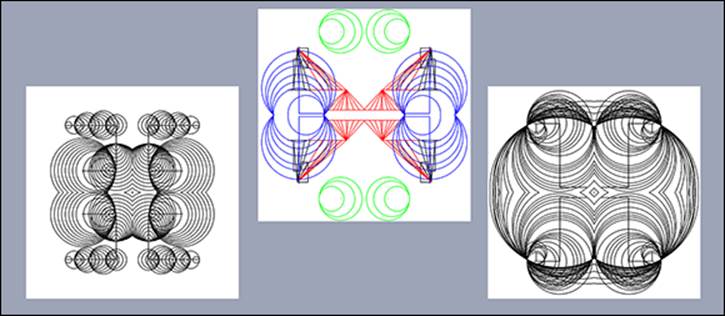
The bulk of the code is the same. Where it differs is that drawing is done in a memory area called segment. When it comes to updating the screen, this segment is drawn four times on the screen in each quadrant of the screen. Each time it is drawn it is flipped either horizontally or vertically to show mirror symmetry in each quadrant. The variable segSize at the start of the code makes it easy to define any size of square window you like for your system. The results of a few tests are shown in Figure 15.8.
Figure 15-8: Some drawings with four-fold symmetry.
Over to You
Improvements you could make include a stealth mode in which the drawing point is moved without leaving a trail or cutting through existing drawings. For that you have to look at the pixel at the drawing point and redraw the colour over the old grey square. Another thing you could try is to alter the way the circle is drawn with the set point defining the centre and the current point the radius. You can have the two modes available on different keys.
That last program had four-fold symmetry. Consider what it would take to produce five-, six- or any number fold symmetry. Four-fold is easy because the segments you draw in are square, and you just used the flip transformation on the segment for each screen quadrant. However, Pygame has a rotate function that you could apply many times to build up the screen. The point is that the shape of the segment you want to plot is not rectangular but triangular. What you would have to do is to draw in a rectangular segment and then mask it by drawing two triangles on either side of the wanted triangle and filling them with transparent pixels to get a triangular segment. Then you have to rotate that and fill in the screen. This is one of those projects that you will not get right the first time – and serendipity or happy accident might give you something even more interesting that you were trying to create.
If you want to look more at the automatic postings, look at the code at https://github.com/ept/uploadr.py. This is an earlier version of the folders2flickr code used in this chapter. However, it has some differences you could find useful. You can use the same Flickr secret and API key numbers used in folders2flickr; there is no need to apply for your own. This can be set up as a task that runs in the background; every minute it looks at the designated folder to see if there is anything new that needs uploading. This can be a useful computerwide utility.
As to the rotary encoders themselves – see if you can incorporate them as a controller for the games in Chapters 5, “Ping”, and 6, “Pie Man”. Continuous rotation can be useful in a lot of control situations. The tilt switch also could be used to make a tilting joystick controller if you had four of them.