Programming 3D Applications with HTML5 and WebGL (2013)
Part II. Application Development Techniques
Chapter 11. Developing a 3D Environment
The techniques explored in Chapter 10 cover a lot of use cases. A single 3D model as the centerpiece of interactive content can be used to market, sell, inform, and entertain. But many 3D applications need more. If we want to develop an immersive game, an architectural walkthrough, or an interactive training system, we will need to learn how to create 3D environments, with multiple objects and more complex types of interaction.
In this chapter, we will develop a 3D environment with realistic scenery, moving objects, and the ability for the user to navigate within the scene by interactively controlling the camera. Extending the theme we developed in Chapter 10, we are going to create a virtual city and take the Futurgo concept car for a test drive. Figure 11-1 shows the application.
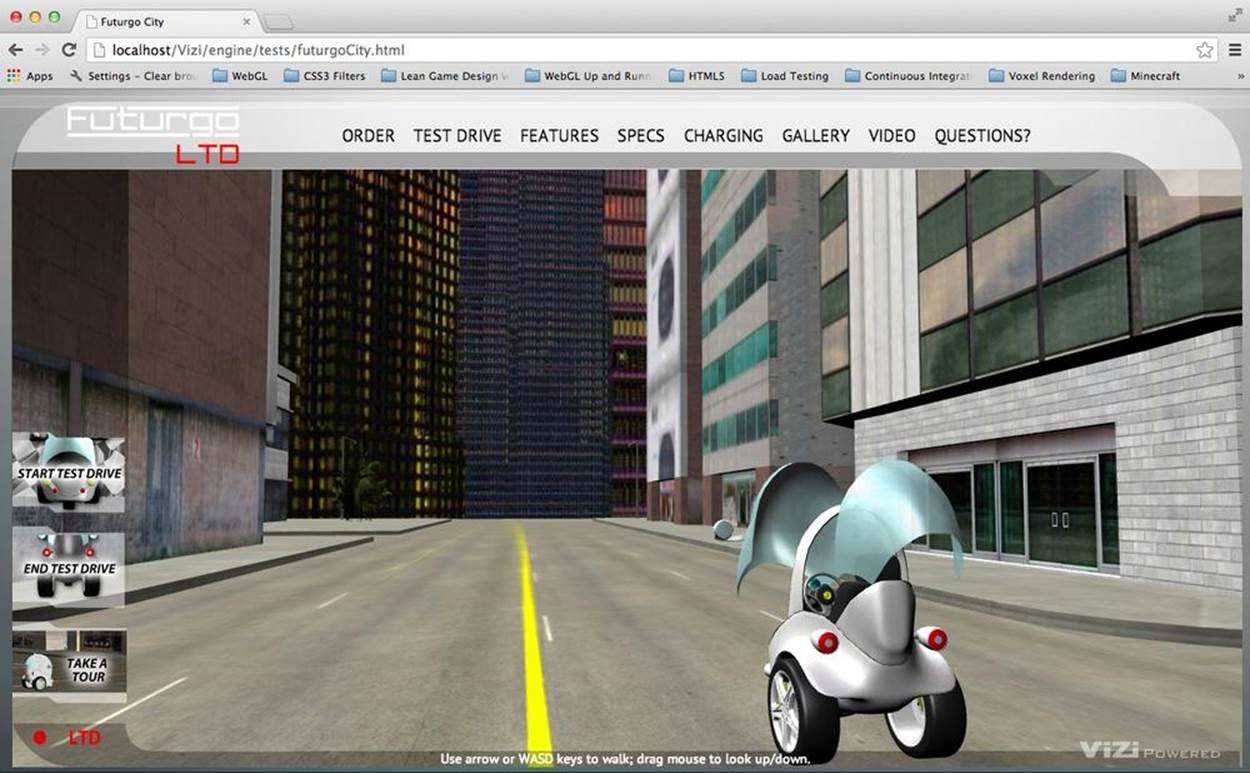
Figure 11-1. The Futurgo concept car in a 3D environment
The Futurgo LTD waits parked on a city street, ready for a test drive. The scene spans a few city blocks, with skyscrapers looming in the distance against a dusky sky, reflected in the office buildings nearby. Using the mouse, you can click and drag to look up, down, left, and right. Move forward, back, left, and right using the arrow keys on your keyboard. Walk up to the Futurgo, and click on it to jump inside and take it for a spin. This world may look a little foreboding—but we’ll be safe inside our own personal transportation device!
Load the file Chapter 11/futurgoCity.html into your browser to try it out. In the course of building this application, we will explore several development topics:
Creating environment art
Assembling a realistic 3D city scene with roads, buildings, and park areas.
Previewing and testing
Adding functionality to the previewer developed in the previous chapter. For this project, we need a previewer that can load multiple files into a single scene, show us the structure of the scene graph, and allow us to inspect the properties of various objects, in preparation for developing the application.
Creating a 3D background
Adding a realistic skyline backdrop to the scene using a skybox—a textured cube placed infinitely far away in the background. The same skybox texture is also used as a cubic environment map reflecting the skyline on the city buildings and vehicle.
Integrating the 3D with the application
Managing the details of loading multiple models into the same application, and adjusting the car model’s lighting, position, and other properties to match the surrounding environment.
Implementing first-person navigation
Providing ways for the user to look around and move within the scene via the mouse and keyboard, and implementing collision so that the user does not pass through solid objects.
Working with multiple cameras
Switching between cameras, allowing the user to see the environment from different views and explore it in multiple ways.
Creating timed and animated transitions
Using timers and animation techniques to create a sequence of actions when the user enters and exits the car.
Scripting object behaviors
Using the Vizi framework to create custom components to control the behavior and appearance of the Futurgo car.
Using sound
Enhancing the environment by adding HTML5 audio elements.
Rendering dynamic textures
Providing real-time user feedback by programmatically updating textures of 3D objects using the 2D Canvas API.
The virtual environment we will create in this chapter is quite simple. A typical game or other 3D environment would have many more objects and more sophisticated interactions, but the techniques covered here provide a good starting point for learning how to develop something morecomplex.
Creating the Environment Art
To develop the 3D environment, I once again worked with artist TC Chang. Creating the art for a city backdrop is time-consuming, so TC and I decided to look for an existing model. We found an excellent candidate on TurboSquid, depicted in Figure 11-2.
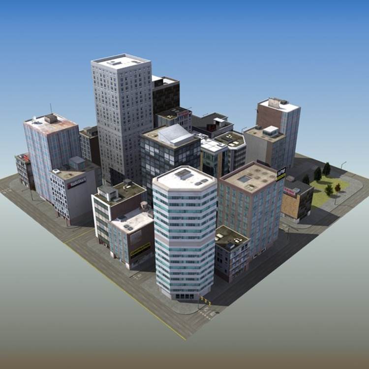
Figure 11-2. City model created by ES3DStudios; image courtesy TurboSquid
The city model was created with the Lightwave modeler. The artist had already converted it to a variety of formats, including Autodesk Maya. After we purchased and downloaded the model, TC brought it into Maya to prepare it for use in the application. The model came with fully detailed, textured buildings, but no lights. TC added three light sources, at which point the model was pretty much ready to go. After exporting to COLLADA for use in the previewer (see next section), we found one small issue with transparency on some texture maps; overall, however, it required very little additional art labor to use this model in the application.
Previewing and Testing the Environment
To test a complex model like the city scene, we need a previewer similar to the one we built in Chapter 10, but with more functionality. The new, improved previewer, shown in Figure 11-3, adds the following features:
Multiple viewing modes
The ability to view content as either a single model with the camera pointed at its center, or as a scene with the camera pointed toward the ground plane.
Scene graph inspection
A tree-based view of the scene graph showing object names and parent/child relationships.
Object inspection
A pop-up property sheet that displays the details of each object, including transform information, mesh statistics, material properties, and camera and light parameters.
Bounding box display
A wireframe box displayed around the selected object, with an option to display wireframe bounding boxes around all the objects in the scene.
Previewing multiple objects
The ability to load multiple additional objects into the same preview so the combined result can be viewed and tested.
Launch the file Chapter 11/previewer.html. Click the Open button to see a file open dialog; open the file ../models/futurgo_city/futurgo_city.dae. Using the Cameras list, select the camera labeled [default] to free-navigate. Using the mouse to rotate and the trackpad/scroll wheel to zoom, you can inspect the city model. (Note that the other cameras do not allow you to free-navigate with the mouse—only [default].)
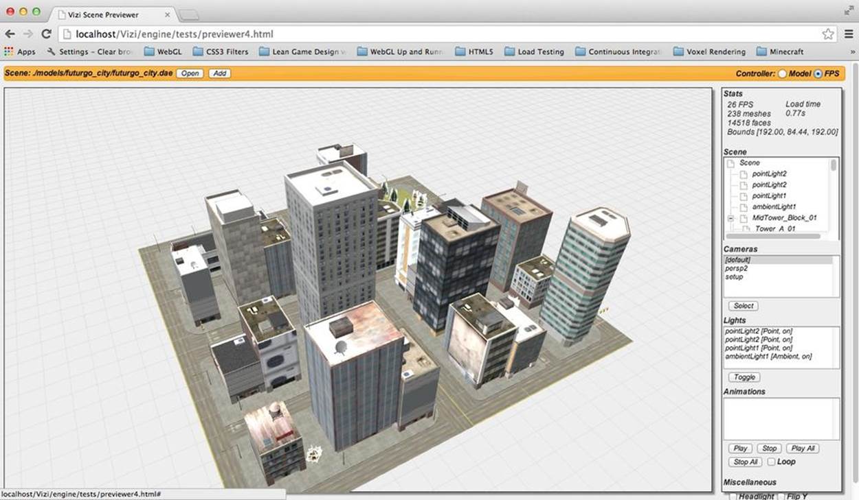
Figure 11-3. The city environment displayed in the Vizi previewer
Previewing the Scene in First-Person Mode
As you rotate and zoom the city model, you may notice that the camera never quite reaches the ground (street) level of the scene. This is because the previewer is designed by default to treat the model as a single object, with the camera view pointed at the geometric center of the object. The single-object scheme doesn’t work so well for environments, so we have added another viewing mode to help.
At the top right of the previewer interface, there is a radio button group allowing you to switch viewing modes. The group is labeled Controller, to distinguish between two different camera controller modes, Model and First Person (or FPS). Our city application will be using a first-person controller; that is, one designed for navigating within an environment as opposed to looking at a single model. (First-person navigation will be discussed in some detail later in this chapter.) Click the FPS button; the camera will drop so that the center of rotation is now at street level, and you can zoom directly to the street.
Note that the FPS mode of the previewer does not actually use a first-person navigation mode to view the model. It simply places the camera in a similar position to the camera you would see in real first-person mode, one that is more suitable for previewing a full environment. The previewer is still using a model controller internally, so that we can zoom and rotate around the entire model quickly. In other words, sometimes we want to treat the scene as a single model for easy manipulation, and other times we want to emulate the views we will see when navigating the environment within the application. The FPS button for the previewer user interface is a simple hack that gives us the best of both.
Inspecting the Scene Graph
As the scenes we work with become more complex, we need the previewer tool to be able to view them at a finer level of detail. The city scene, for example, consists of over 200 separate meshes, as indicated in the Scene Stats pane in the previewer. To program interactivity into the application, we will need to find the names, sizes, and locations of the individual objects, as well as other properties such as their type (e.g., mesh, camera, or light), and how the objects are grouped into hierarchies. This is especially important when working with models obtained from a third party, where we were not in close communication with the artist when the content was created.
One crude way to inspect the scene graph is to open the COLLADA or glTF file in a text editor and search for specific text strings indicating the type. But it would be a maddening experience for most developers, and it would require detailed technical knowledge of how those file formats are organized. (I personally know both file formats very well; however, I have no patience for poring through huge text files looking for needles in a haystack.) A much better approach is to have the previewer tool present this information for us.
The enhanced previewer contains a new pane, Scene, with a listbox presenting a scrolling tree view of the scene graph hierarchy. Take a moment to scroll through the list, and click on the plus and minus icons to expand/contract the levels of the hierarchy and see how it is organized: at the top level, there are a handful of lights, followed by a group named MidTower_Block_01, and then a few cameras. Notice the plus sign next to the group. If you click on that, the group expands to show the next level of children, with names like Tower_A_01, Roof_Detail_01, and so on. Some of those groups can themselves expand to show additional child objects.
Armed with the ability to see node names and hierarchical relationships within the scene, we can now determine the objects to which we will add interactivity and other details in the running application. For example, after loading the scene into the application, we plan to add environment maps that reflect the skybox background, but only to the buildings, not to the roads or park areas. A scan through the scene hierarchy shows us that the building names all begin with “Tower” or “Office,” so we will be able to use the Vizi.Object.map() scene graph API method to find all objects that match a regular expression with this pattern, and change their materials. We will walk through the code to do this a little later in the chapter.
The tree view control used in the previewer was implemented with a jQuery plugin called dynatree. Example 11-1 shows the code to initialize the tree view control with various options, and set up handlers for when items are clicked or double-clicked. The source code for the previewer can be found in the file Chapter 11/previewer.html.
Example 11-1. Initializing the dynatree tree view control
function initSceneTree(viewer) {
// Initialize the tree inside the <div> element.
$("#scene_tree").dynatree({
imagePath: "./images/previewer_skin/",
title: "Scene Graph",
minExpandLevel: 2,
selectMode: 1,
onDblClick: function(node) {
openSceneNode(viewer, node);
},
onActivate: function(node) {
selectSceneNode(viewer, node);
if (infoPopupVisible) {
openSceneNode(viewer, node);
}
},
onDeactivate: function(node) {
},
onFocus: function(node) {
},
onBlur: function(node) {
},
});
}
Now let’s talk about how we populate the tree view control based on the contents of the scene graph after a scene file is loaded. First, we have a line in the load callback to call a helper function, updateSceneTree().
function onLoadComplete(data, loadStartTime)
{
// Hide the loader bar
var loadStatus = document.getElementById("loadStatus");
loadStatus.style.display = 'none';
viewer.replaceScene(data);
var loadTime = (Date.now() - loadStartTime) / 1000;
var loadTimeStats = document.getElementById("load_time_stats");
loadTimeStats.innerHTML = "Load time<br>" + loadTime.toFixed(2) + "s"
// Vizi.System.log("Loaded " + loadTime.toFixed(2) + " seconds.");
updateSceneTree(viewer);
updateCamerasList(viewer);
updateLightsList(viewer);
updateAnimationsList(viewer);
updateMiscControls(viewer);
if (viewer.cameraNames.length > 1) {
selectCamera(1);
}
addRollovers(viewer, data.scene);
}
updateSceneTree() does a couple of things. First, it reinitializes the tree control widget, in case it was previously populated for viewing another scene, by calling removeChildren() on the root node of the tree view. Then, it calls another function, buildSceneTree(), to iterate through the scene graph and populate the items in the tree control. Note that the call is wrapped in a setTimeout() to delay it slightly; the delay makes for a friendlier user experience. Building a tree view with dynatree takes a little bit of time, and we don’t want that to slow down the initial rendering of the scene. So we put in a placeholder message to start, which we rip out once the timeout fires.
function updateSceneTree(viewer) {
// Sample: add a hierarchic branch using code.
// This is how we would add tree nodes programatically
var rootNode = $("#scene_tree").dynatree("getRoot");
rootNode.removeChildren();
var initMessage = rootNode.addChild({
title: "Initializing...",
isFolder: false,
});
setTimeout(function() {
rootNode.removeChild(initMessage);
rootNode.expand(false);
var i, len = viewer.scenes.length;
for (i = 0; i < len; i++) {
buildSceneTree(viewer.scenes[i], rootNode);
}
}, 1000);
}
The code to populate the scene tree display is actually fairly simple. The source for function buildSceneTree() is located in the file Chapter 11/sceneTree.js. Example 11-2 shows the function in its entirety.
Example 11-2. Populating the scene tree display
sceneTreeMap = {};
buildSceneTree = function(scene, tree) {
function build(object, node, level) {
var noname = level ? "[object]" : "Scene";
var childNode = node.addChild({
title: object.name ? object.name : noname,
expand: level <= 1,
activeVisible:true,
vizi:object,
});
sceneTreeMap[object._id] = childNode;
var i, len = object._children.length;
for (i = 0; i < len; i++) {
build(object._children[i], childNode, level+1);
}
}
build(scene, tree, 0);
}
First, we initialize a global object, sceneTreeMap, which will be used to associate Vizi objects in the Vizi scene graph with items in the tree view control. We will use this shortly to support clicking on an object within the scene, and seeing the associated item highlighted in the control.
Inside the body of buildSceneTree(), we define a nested function, build(), that will recursively add items to the tree control. For each object in the Vizi scene graph, the function creates a new tree control node by calling node.addChild(). This method creates a new item with the supplied parameters.
title specifies the label to display for the item. expand indicates whether to initially display the item expanded; we do this only for items at the top level of the scene graph. Setting activeVisible tells the tree view control to scroll to an item and select it if it is “activated” (i.e., selected from within the code, such as when the associated object is clicked within the scene). The last parameter passed in is vizi, the Vizi scene graph object that will be used whenever the user clicks on an item in the tree view control. When clicked, the previewer will highlight the object with a yellow wireframe box, and double-clicking will display a pop up with its properties (see the next section).
Once the tree control item is created, we add it to sceneTreeMap for later use, and call build() recursively to add tree control items for the object’s children, if it has any.
NOTE
A lot of work goes into building a good HTML-based tree view. Thankfully, the developers of dynatree have saved us that pain. dynatree lets you instantly create a tree view of any hierarchical HTML list. It also has a feature-packed, easy-to-use API for creating/modifying/deleting items, and it supports full visual customization. dynatree is hosted on Google code.
Inspecting Object Properties
The previewer allows us to inspect each object’s properties. Double-click on an object in the scene tree view, and a tabbed jQuery dialog, or property sheet, pops up to display the details. See the screenshot in Figure 11-4. The property sheet shows the properties for the object namedTower_D_01. It contains three tabs: one for the transform information (position, rotation, and scale); one with details on the geometry, including the number of vertices and faces in the mesh, and its bounding box; and finally, information about the material, including the shading model, colors, and name of the image file for the texture map.
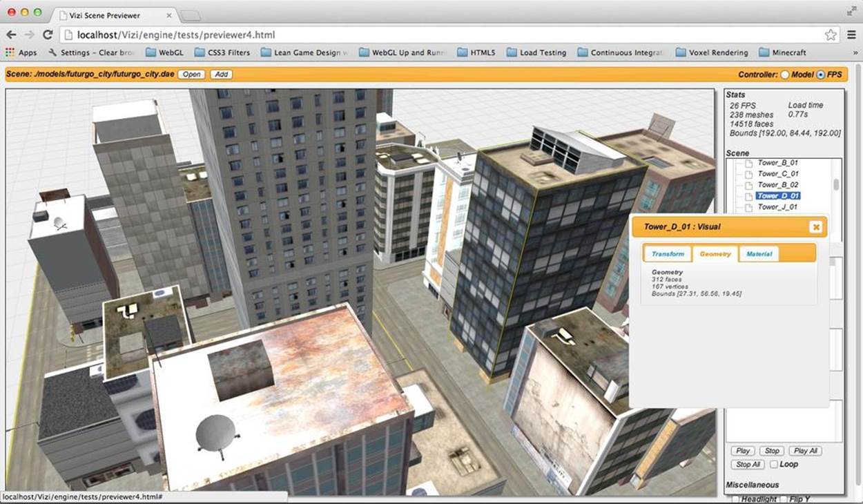
Figure 11-4. Using the previewer to inspect object properties
The previewer also allows us to inspect an object’s properties by clicking on the object itself in the 3D scene. If you single-click on the object while the property sheet is still displayed, its contents will be replaced with properties for the new object. If the property sheet pop up is not visible, you can double-click on the object to pop up the dialog with the new properties.
Example 11-3 shows the code that adds click handling within the 3D scene (located in the source file Chapter 11/previewer.html), so that the user can select individual objects. The function addRollovers() uses the Vizi scene graph API method map() to find every object in the scene and add mouse handling by creating a new Vizi.Picker object. The code adds event handlers for mouse down, up, over, and double-click.
Example 11-3. Implementing object selection within the scene
function addRollover(viewer, o) {
var picker = new Vizi.Picker;
picker.addEventListener("mouseover", function(event) {
onPickerMouseOver(viewer, o, event); });
picker.addEventListener("mouseout", function(event) {
onPickerMouseOut(viewer, o, event); });
picker.addEventListener("mouseup", function(event) {
onPickerMouseUp(viewer, o, event); });
picker.addEventListener("dblclick", function(event) {
onPickerMouseDoubleClick(viewer, o, event); });
o.addComponent(picker);
}
function addRollovers(viewer, scene) {
scene.map(Vizi.Object, function(o) {
addRollover(viewer, o);
});
}
The event handler code for mouse up, which is used to detect a single click, and the handler for mouse double-click are shown next. They are almost identical. First, we check the button code of the event, because the previewer supports selection only with the left mouse button. If the left mouse button was used, we call Vizi.Viewer’s highlightObject() method. This draws a yellow wireframe box around the clicked object. (We will look at the details of implementing bounding box highlighting in the next section.)
Now, we highlight the associated item in the tree view, using the Vizi object’s _id property—a property that is automatically generated by the Vizi engine when the object is created—as the index to look up which tree item to highlight. Finally, if it is a single click and the property sheet is already visible (flagged in the Boolean variable infoPopupVisible), we call openSceneNode(), a helper function that repopulates the property sheet’s contents with the newly selected node. For the double-click case, we call openSceneNode() regardless, and the dialog will be popped up if it was not already visible.
function onPickerMouseUp(viewer, o, event) {
if (event.button == 0) {
viewer.highlightObject(o);
node = selectSceneNodeFromId(viewer, o._id);
if (node && infoPopupVisible) {
openSceneNode(viewer, node);
}
}
}
function onPickerMouseDoubleClick(viewer, o, event) {
if (event.button == 0) {
viewer.highlightObject(o);
node = selectSceneNodeFromId(viewer, o._id);
openSceneNode(viewer, node);
}
}
Displaying Bounding Boxes
The previewer uses bounding box display for a couple of purposes: to highlight the selected object, and to show the bounding boxes for all objects if you choose that option in the user interface.
To highlight the selected object, Vizi.Viewer provides a method called highlightObject(). Example 11-4 shows the implementation. First, the viewer removes the highlight on the current object, if one exists. Then, it computes the bounding box of the new object, using that to create a yellow wireframe box that it will place around the object.
There are a few subtleties to this; see the lines of code highlighted in bold. We create a Vizi.Decoration object to contain the bounding box cube geometry. This class is a special subclass of Vizi.Visual that the framework uses to render content that you can see, but not interact with; it will not interfere with picking or collision. After that, we add the decoration to the parent of the object, not the object itself. The bounding box for any object is computed in the coordinate system of the parent, so we need to add it to the scene graph as a child of the parent in order for the box to be transformed correctly.
Example 11-4. Creating the highlight box for the selected object
Vizi.Viewer.prototype.highlightObject = function(object) {
if (this.highlightedObject) {
this.highlightedObject._parent.removeComponent(
this.highlightDecoration);
}
if (object) {
var bbox = Vizi.SceneUtils.computeBoundingBox(object);
var geo = new THREE.CubeGeometry(bbox.max.x - bbox.min.x,
bbox.max.y - bbox.min.y,
bbox.max.z - bbox.min.z);
var mat = new THREE.MeshBasicMaterial({color:0xaaaa00,
transparent:false,
wireframe:true, opacity:1})
var mesh = new THREE.Mesh(geo, mat);
this.highlightDecoration = new Vizi.Decoration({object:mesh});
object._parent.addComponent(this.highlightDecoration);
var center = bbox.max.clone().add(bbox.min)
.multiplyScalar(0.5);
this.highlightDecoration.position.add(center);
}
this.highlightedObject = object;
}
The previewer allows you to see the bounding boxes for all objects. In the Miscellaneous pane on the bottom right, there is a checkbox labeled Boxes. Click that to turn on bounding box display. You should see green wireframe objects similar to those depicted in Figure 11-5.
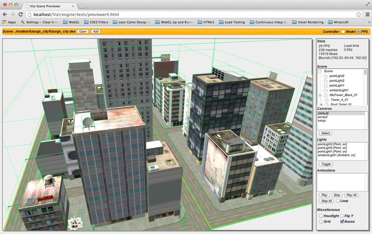
Figure 11-5. The previewer displaying bounding boxes for all objects in the scene
The code to display bounding boxes for each object is similar to creating the highlight box, only this time we apply it to every object in the scene graph using the Vizi scene graph map() API method. See Example 11-5.
Example 11-5. Creating rendered bounding boxes for all objects in the scene
this.sceneRoot.map(Vizi.Object, function(o) {
if (o._parent) {
var bbox = Vizi.SceneUtils.computeBoundingBox(o);
var geo = new THREE.CubeGeometry(bbox.max.x - bbox.min.x,
bbox.max.y - bbox.min.y,
bbox.max.z - bbox.min.z);
var mat = new THREE.MeshBasicMaterial(
{color:0x00ff00, transparent:true,
wireframe:true, opacity:.2})
var mesh = new THREE.Mesh(geo, mat);
var decoration = new Vizi.Decoration({object:mesh});
o._parent.addComponent(decoration);
var center = bbox.max.clone().add(bbox.min)
.multiplyScalar(0.5);
decoration.position.add(center);
decoration.object.visible = this.showBoundingBoxes;
}
});
Now, when the user clicks the Boxes option to toggle that feature, the previewer calls the viewer’s setBoundingBoxesOn() method. The function uses map() to find each object of type Vizi.Decoration and toggle its visibility by setting its visible property.
Vizi.Viewer.prototype.setBoundingBoxesOn = function(on)
{
this.showBoundingBoxes = !this.showBoundingBoxes;
var that = this;
this.sceneRoot.map(Vizi.Decoration, function(o) {
if (!that.highlightedObject || (o != that.highlightDecoration)) {
o.visible = that.showBoundingBoxes;
}
});
}
Previewing Multiple Objects
When you are building an environment using multiple objects, it is critical to be able to preview and test them together. We need to make sure objects are modeled to the same scale, positioned properly relative to each other, lit compatibly, and so on. This is especially true if the objects are coming from multiple sources, created by different artists, or hosted at different model-sharing sites.
Let’s bring the Futurgo car model into the city scene to test these properties. Click Add on the menu bar at the top. In the file selection dialog, choose ../models/futurgo_mobile/futurgo_mobile.json. (Make sure you are using the default camera and are looking at the main road in the center of the scene; this is where the model will appear.) The model should appear in the center of the scene. Zoom up to it for a closer look, as depicted in Figure 11-6.
The code to add more models into the existing scene is nearly identical to that for loading the original model: create a Vizi.Loader object, add an event listener for when the model is loaded, and in the event listener, add new scene objects to the viewer. The only difference is that we willadd the objects to the viewer, not replace them. Example 11-6 shows the code (from source file Chapter 11/previewer.html). We call viewer.addToScene(), which adds the objects to the running scene graph (in this case, the Futurgo car model), and updates the viewer’s data structures. Then we update the user interface elements as before: the tree view, and the lists of lights, cameras, and animations.
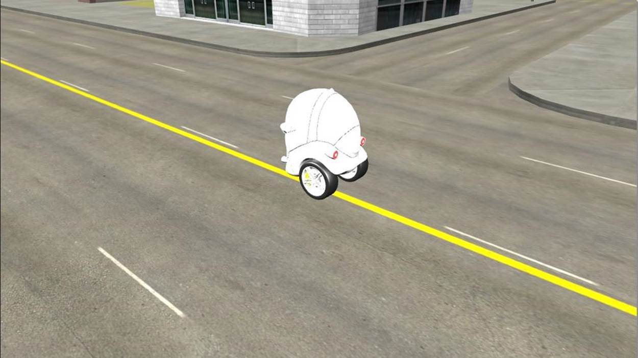
Figure 11-6. The Futurgo model added to the city scene
Example 11-6. Inserting additional models into the scene
function onAddComplete(data, loadStartTime)
{
// Hide the loader bar
var loadStatus = document.getElementById("loadStatus");
loadStatus.style.display = 'none';
viewer.addToScene(data);
var loadTime = (Date.now() - loadStartTime) / 1000;
var loadTimeStats = document.getElementById("load_time_stats");
loadTimeStats.innerHTML = "Load time<br>" + loadTime.toFixed(2) + "s"
// Vizi.System.log("Loaded " + loadTime.toFixed(2) + " seconds.");
updateSceneTree(viewer);
updateCamerasList(viewer);
updateLightsList(viewer);
updateAnimationsList(viewer);
updateMiscControls(viewer);
addRollovers(viewer, data.scene);
}
You may have noticed how overly bright the Futurgo looked when it was added to the scene. This is because the Futurgo model contains its own lights, which we used in the application we built in Chapter 10. I could have asked TC to make a special version of the car without lights for use in this application, but there is no need. Using the previewer, we can figure out which lights are causing the problem and turn them off, then note the names of the lights for when we want to do the same in the application.
Using the previewer’s Lights list, we turn off the offending lights. I had a notion (correctly so) that they would be lights added to the end of the list, since the Futurgo model was added to the scene last. So I turned off the three point lights at the end of the list. The car still looked a little washed-out, so I turned off the ambient light as well. This did the trick. Figure 11-7 shows the result with those four lights turned off. See the oval highlighting the changed values in the user interface.
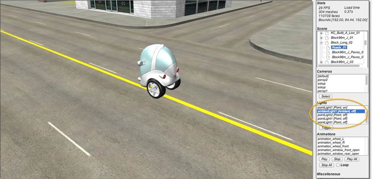
Figure 11-7. The Futurgo model in the city scene, after the lighting has been adjusted
Using the Previewer to Find Other Scene Issues
Using the previewer turned up an additional technical issue with this scene: the trees. The creator of this scene used a time-tested hack to render trees cheaply: a set of overlapping flat polygons with texture maps of the tree from different angles. Typically, there are two vertical polygons arranged in an X pattern, and one or more horizontal polygons crisscrossing the X shape. This is one of those cheap tricks modelers have used for years to save polygons; imagine the number of triangles required to make the leaves of a tree look realistic otherwise.
The only problem with using the author’s tree setup in WebGL is the choice of image file format: the textures for each polygon were created as a pair of Microsoft BMP files, one with the color information, and the second with an alpha mask. We don’t know how to deal with that easily in Vizi/Three.js. It is technically possible, but the engine does not currently support it. So I asked TC to convert the tree BMP image file pairs to a single PNG with alpha channel. He did so, updated the Maya file, and re-exported. The before-and-after comparison is shown in Figure 11-8.
NOTE
While the image on the right hardly seems better, it actually renders properly in the live application. The artifact you see here is due to a limitation of the current previewer implementation. Even though there is transparency information in the PNG file, neither Vizi nor Three.js know this fact without the author setting a transparency value on the material itself. Since those values were not specified in the content, we will have to set them manually in the application after the scene is loaded.
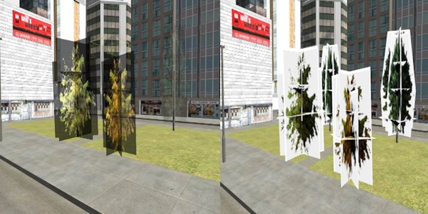
Figure 11-8. This side-by-side comparison of trees using overlapping rectangular geometry depicts the texture maps in the previewer, before and after conversion from two BMP files with alpha mask (left) to a single PNG (right); the white areas surrounding the trees on the right are artifacts of the previewer, and will disappear in the application code when we explicitly tell Three.js to use transparency
Creating a 3D Background Using a Skybox
Now that we’ve previewed and debugged the city art, and seen how the Futurgo will integrate with it, it’s time to start building the application. But first, we need to deal with another topic. The art for this city model is nice, but it is confined to the four city blocks it spans. If we want a compelling, realistic scene through which to drive the car, we need to create the illusion of a much bigger city. We can do that by rendering a skybox background.
3D Skyboxes
Unlike a typical background image for a web page, we need the background for our scene to be 3D: as the camera moves around, we expect to see the backdrop change. A skybox is a panoramic image consisting of six texture maps wrapped on the inside of a cube. The cube is rendered from a stationary camera that rotates along with the camera, exposing different parts of the background. Skyboxes are a dead simple way to provide a realistic 3D painted background.
The Three.js example set features a few demonstrations of skybox functionality. Open the file webgl_materials_cubemap_balls_reflection.html in the Three.js examples to see one in action. This looks great in this example. However, it is based on a crude implementation of skyboxes that has a serious limitation. In these examples, the authors simply create a really big cube at the outer edges of the scene. It looks far away, but if you were able to navigate around the scene, you would actually be able to get closer to one of the edges of the box, and eventually even reach it, destroying the illusion.
NOTE
Illusion is everything in 3D graphics. Skyboxes create a convincing illusion of an infinite background landscape—but only if you never get closer to it as you move. If you have ever seen Peter Weir’s genius film The Truman Show, recall the scene in which Truman slams into a solid wall, painted with the backdrop of the artificial world created for him by the show’s director. Once he ran into that wall…the jig was up.
The Vizi Skybox Object
To create a convincing city scene, we need to use a proper skybox. Happily, the Vizi framework comes with one. Before we put a skybox into the city application, let’s create a simple example to show how it’s done. Open the sample in Chapter 11/skybox.html, depicted in Figure 11-9. Using the mouse, rotate around to see the whole background. Using the trackpad or scroll wheel, zoom in and out. The cube gets closer and farther away, but the box stays infinitely far away. Note how the skybox background is also reflected on the surface of the foreground cube; this effect is accomplished through a cubic environment map created with the same texture.
The panoramic image of the skybox consists of six bitmaps laid out as depicted in Figure 11-10. The bitmaps have been created so that they stitch together perfectly when mapped onto the inside faces of a cube.
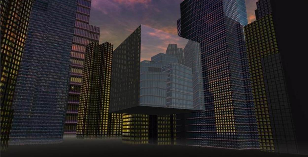
Figure 11-9. A skybox background, with a cube in the foreground—as the user moves forward and back, the cube gets closer or farther away, but the background remains at an infinite distance; the cube reflects the background art using a cubic environment map with the same texture
|
|
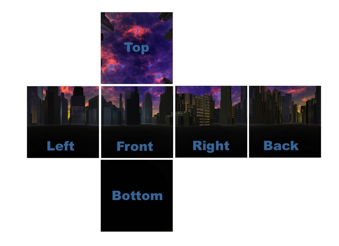
Figure 11-10. The six textures composing the cube map of the skybox background (skybox textures from http://www.3delyvisions.com/skf1.htm)
Example 11-7 shows the code to create the skybox and add it to the scene. First, we use the Three.js utility to create a cubic texture map, THREE.ImageUtils.loadTextureCube(). Then, we call a Vizi function to create the skybox prefab (or prebuilt object), Vizi.Prefabs.Skybox(). We then set the skybox’s texture property to the cube texture, and add it to the application.
Example 11-7. Creating the skybox background
var app = new Vizi.Application({ container : container });
// Skybox from http://www.3delyvisions.com/
// http://www.3delyvisions.com/skf1.htm
var path = "../images/sky35/";
var urls = [ path + "rightcity.jpg", path + "leftcity.jpg",
path + "topcity.jpg", path + "botcity.jpg",
path + "frontcity.jpg", path + "backcity.jpg" ];
var cubeTexture = THREE.ImageUtils.loadTextureCube( urls );
var skybox = Vizi.Prefabs.Skybox();
var skyboxScript = skybox.getComponent(Vizi.SkyboxScript);
skyboxScript.texture = cubeTexture;
app.addObject(skybox);
NOTE
So…what’s with this “prefab” business?
In Vizi, a prefab is a prebuilt set of objects and components that can be created and dropped right into a scene. The prefab design pattern occurs frequently in game engines such as Unity. Recall that in modern game engine design, the trend has moved away from creating classes to extend functionality, and toward aggregating simple components into richer structures.
In the case of the Vizi skybox, it is a cube set up to draw in the background and track the movements of the main camera so that it keeps the cube properly oriented. If you are curious about how the Vizi skybox prefab is implemented, refer to the file objects/skybox.js in the Vizi source tree.
The cube in this example appears to reflect the background skybox image. We did this easily, by using the same cubic texture map as an environment map on the cube’s material. The code to do this is shown in Example 11-8.
Example 11-8. Adding the cube map to a foreground object
var cube = new Vizi.Object;
var visual = new Vizi.Visual(
{ geometry: new THREE.CubeGeometry(2, 2, 2),
material: new THREE.MeshPhongMaterial({
color:0xffffff,
envMap:cubeTexture,
reflectivity:0.8,
refractionRatio:0.1
})
});
cube.addComponent(visual);
app.addObject(cube);
Integrating the 3D Content into the Application
Using the previewer, we have browsed through the scene graph to find the names and properties of objects and gotten a look at lighting and other visual aspects of the content, taking note of things that need to be done with the models once loaded into the app. We also studied how to build a skybox background and reflect it onto objects in this scene. We are finally ready to assemble our 3D environment into an application.
Loading and Initializing the Environment
The Futurgo test drive application is located in the HTML file Chapter 11/futurgoCity.html. The jQuery-ready code for this file is very simple; it just creates an instance of the class FuturgoCity, which loads the models, assembles the scene, and runs the application. The source code forFuturgoCity can be found in the file Chapter 11/futurgoCity.js.
The application’s setup begins by loading the city model. The file load callback, onLoadComplete(), assembles the environment from there. Refer to Example 11-9. After calling the viewer’s replaceScene() method to add the newly loaded content to the scene, we ask the viewer to use first-person navigation by calling setController("FPS"). (We will discuss camera controllers and first-person navigation in detail later in the chapter.) We then save the information about the viewer’s camera controller and current camera; we’ll need those later. After that, we call several helper methods to add the skybox and environment maps, and do other important setup tasks.
Example 11-9. Callback code called after environment load
FuturgoCity.prototype.onLoadComplete = function(data, loadStartTime)
{
var scene = data.scene;
this.scene = data.scene;
this.viewer.replaceScene(data);
if (this.loadCallback) {
var loadTime = (Date.now() - loadStartTime) / 1000;
this.loadCallback(loadTime);
}
this.viewer.setController("FPS");
this.cameraController = this.viewer.controllerScript;
this.walkCamera = this.viewer.defaultCamera;
this.addBackground();
this.addCollisionBox();
this.fixTrees();
this.setupCamera();
this.loadFuturgo();
}
addBackground() creates the skybox, as in the example from the previous section. Then, it adds the environment maps to the buildings. Recall that we used the previewer to find the names of the big buildings. All of them began with the string “Tower” or “Office.” Note the line in bold with the regular expression. We use the Vizi scene graph map() method to find the matching objects, and set the environment map on the Three.js material for each object.
this.scene.map(/Tower.*|Office.*/, function(o) {
var visuals = o.visuals;
if (visuals) {
for (var vi = 0; vi < visuals.length; vi++) {
var v = visuals[vi];
var material = v.material;
if (material) {
if (material instanceof THREE.MeshFaceMaterial) {
var materials = material.materials;
var mi, len = materials.length;
for (mi = 0; mi < len; mi++) {
addEnvMap(materials[mi]);
}
}
else {
addEnvMap(material);
}
}
}
}
});
Next, we are going to add a collision box. Later in this chapter, we will see how to implement collision to go with navigating the scene in first-person mode. For now, here is the code to set up an invisible box at the boundaries of the city, so that we can’t walk or drive outside of those limits. It is pretty simple: create a new Vizi.Visual that contains a cube with dimensions matching the bounding box of the scene, and make sure it is transparent by setting its material’s opacity to 0. Additionally, we want to make sure that we collide against the inside of the cube, by asking Three.js to render the backfaces of the cube’s geometry via setting its side property to the enumerated value THREE.DoubleSide (i.e., render both sides of the cube). The code is listed in Example 11-10.
Example 11-10. Adding a collision box to the scene
FuturgoCity.prototype.addCollisionBox = function() {
var bbox = Vizi.SceneUtils.computeBoundingBox(this.scene);
var box = new Vizi.Object;
box.name = "_futurgoCollisionBox";
var geometry = new THREE.CubeGeometry(bbox.max.x - bbox.min.x,
bbox.max.y - bbox.min.y,
bbox.max.z - bbox.min.z);
var material = new THREE.MeshBasicMaterial({
transparent:true,
opacity:0,
side:THREE.DoubleSide
});
var visual = new Vizi.Visual({
geometry : geometry,
material : material});
box.addComponent(visual);
this.viewer.addObject(box);
}
We also need to fix that transparency issue with the trees. In the method fixTrees(), we again use map() to find all nodes whose names begin with “Tree,” find any visuals those nodes contain, and set the transparent property of their materials to true. This flag tells the Three.js rendering system to turn on alpha blending; without it, the trees would be drawn opaquely, as we saw in the previewer in Figure 11-8.
this.scene.map(/^Tree.*/, function(o) {
o.map(Vizi.Visual, function(v){
var material = v.material;
if (material instanceof THREE.MeshFaceMaterial) {
var materials = material.materials;
var i, len = materials.length;
for (i = 0; i < len; i++) {
material = materials[i];
material.transparent = true;
}
}
else {
material.transparent = true;
}
});
});
After placing the camera’s position at a good spot for initial viewing, we are ready for the last big step in setting up the application: loading the car model.
Loading and Initializing the Car Model
Loading and preparing the car model involves several activities: add the loaded model to the scene, add behaviors to fade the windows to various transparency levels, add environment maps to the windows and body to reflect the skybox, take out the extra lights we saw in the previewer, and finally, place the car. After all that, we will still need to set up the interactive objects for driving and animating the car, both of which we will discuss in upcoming sections.
Our file-loaded callback function begins as follows. Call this.viewer.addToScene() to add the object to the scene. Then, as with the application from the previous chapter, we add fade behaviors to the windows and start them off automatically, resulting in the two-second fade to semi-opaque. In addition, we save away the fader objects into the application object’s property faders, an array that will be used later to fade the windows to even more transparent when we go inside the car, and back to semi-opaque when we exit the car. While we are iterating through the window materials, we also add the same environment map that is used on the buildings—namely, the cube map texture of the skyscrapers in the skybox background. Example 11-11 shows this sequence of calls.
Example 11-11. Callback code to handle loading of the Futurgo car
FuturgoCity.prototype.onFuturgoLoadComplete = function(data) {
// Add the Futurgo to the scene
this.viewer.addToScene(data);
var futurgoScene = data.scene;
// Add some interaction and behaviors
var that = this;
// Add environment map and faders to the windows;
// fade the windows on start
this.faders = [];
futurgoScene.map(/windows_front|windows_rear/, function(o) {
var fader = new Vizi.FadeBehavior({duration:2,
opacity:FuturgoCity.OPACITY_SEMI_OPAQUE});
o.addComponent(fader);
fader.start();
that.faders.push(fader);
var visuals = o.visuals;
var i, len = visuals.length;
for (i = 0; i < len; i++) {
visuals[i].material.envMap = that.envMap;
visuals[i].material.reflectivity = 0.1;
visuals[i].material.refractionRatio = 0.1;
}
});
We then add the environment map to the body of the car (metal frame and rearview mirrors).
// Add environment map to the body
futurgoScene.map(/body2/, function(o) {
var visuals = o.visuals;
var i, len = visuals.length;
for (i = 0; i < len; i++) {
visuals[i].material.envMap = that.envMap;
visuals[i].material.reflectivity = 0.1;
visuals[i].material.refractionRatio = 0.1;
}
});
Next, we iterate through all the parts of the body in order to add Vizi.Picker objects. These will allow us to click anywhere on the Futurgo to start the test drive. We save these away into the object’s pickers array, because we are going to disable and re-enable each picker when entering and exiting the car, respectively.
Next, we deal with the lighting issues we saw when previewing the Futurgo imported into the scene using the previewer. The presence of the extra lights in the Futurgo model was causing it to look washed-out when combined with the lights that already existed in the scene. So we need to turn off all lights that came in with the Futurgo model; in addition, we need to turn off the ambient light supplied with the city model.
// The combined lighting from the two scenes
// makes the car look too washed-out;
// Turn off any lights that came with the car model
futurgoScene.map(Vizi.PointLight, function(light) {
light.intensity = 0;
});
// Also turn off the ambient light that came with
// the city model
this.scene.map(/ambient/, function(o) {
o.light.color.set(0, 0, 0);
});
Finally, we place the car in a good initial spot for viewing when we enter the scene. Since the camera’s x and z position values are both zero, we place the car a few units to the right and back from that.
// Drop the Futurgo at a good initial position
var futurgo = futurgoScene.findNode("vizi_mobile");
futurgo.transform.position.set(2.33, 0, −6);
We still need to add some behaviors and interaction to drive the car, which we will cover in later sections—but at this point, the scene is fully assembled. You can see the skybox background and environment map reflections; the car is in place, with the windows faded and environment maps of the background reflecting on the car body. The result is depicted in Figure 11-11, a screenshot of the entry view when the page is loaded.
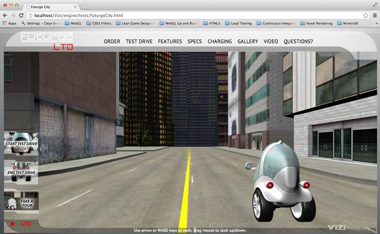
Figure 11-11. Entry view of the Futurgo city application
Let’s take a moment to take this all in. Drag the mouse to look around; use the arrow keys to walk through the scene; see the buildings towering overhead, reflecting the twilight sky. We built this—with just a few days’ work. That’s a pretty impressive accomplishment.
OK, that’s enough dawdling; time to get back to work.
Implementing First-Person Navigation
Now that we have an environment loaded, we need to move around in it. We want to allow the user to explore the city on foot, or take a test drive in the Futurgo. In this section, we will discuss how to implement game-style walking navigation, also known as first-person navigation.
The term first-person, or first-person perspective, refers to rendering a 3D scene from the point of view of the user. Essentially, the camera is placed as if it were between the user’s eyes. First-person navigation is a mode of moving the camera in response to mouse, keyboard, joystick, and/or game controller input. First-person navigation is very popular in video games, especially combat games known as first-person shooters (FPS).
On a desktop computer, first-person navigation is usually operated by the mouse and keyboard, with the mouse controlling the direction the camera points in, and the keyboard moving, sliding, or turning the user. Table 11-1 shows the typical keyboard and mouse bindings used in first-person navigation. The arrow keys are used to move the view forward, back, left, and right, with the W, A, S, and D keys (known collectively as “WASD” or “wazz-dee” keys) mirroring that functionality, which affords the use of the left hand to move while the mouse turns the camera (or shoots at enemies, in the case of a shooter game).
Table 11-1. Typical keyboard and mouse bindings for first-person mode
|
Key/mouse action |
Action |
|
W, up arrow |
Move forward |
|
A, left arrow |
Slide left |
|
S, down arrow |
Move back |
|
D, right arrow |
Slide right |
|
Mouse drag up |
Tilt camera up |
|
Mouse drag down |
Tilt camera down |
|
Mouse drag left |
Turn camera left |
|
Mouse drag right |
Turn camera right |
Take a walk around the city scene using the arrows or WASD keys; look up, down, left, and right by clicking and dragging the left mouse button. See Figure 11-12.
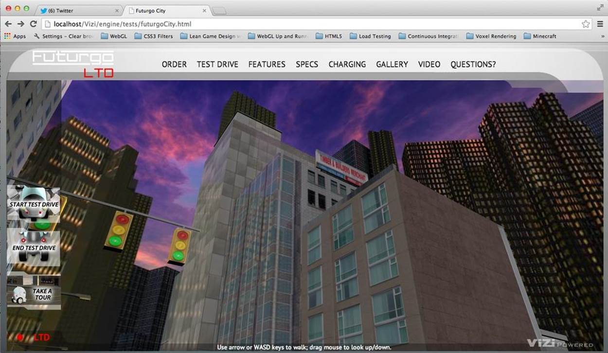
Figure 11-12. Exploring the city in first-person mode
Camera Controllers
To implement first-person navigation, we are going to use an object known as a camera controller. Camera controllers, as the name suggests, control movement of the camera based on user input. Vizi.Viewer supports different camera controller modes: model and first-person. It automatically creates camera controller objects for each mode. Simply call the viewer’s setController(), which takes a string indicating which controller to use; valid values are "model" and "FPS".
The Futurgo application in Chapter 10 used the model controller, a camera controller designed to orbit the camera around the object, always facing at its center. The net effect is that the model appears to rotate as you drag the mouse, or get closer or farther away as you use the trackpad or scroll wheel (when in fact, the camera is being moved). This type of camera controller is perfect for an application that uses a single model. For the city application, however, we are going to use the first-person controller.
First-Person Controller: The Math
The key to implementing a first-person controller is to translate changes in mouse position to rotations of the camera: dragging to the left or right rotates the camera about its current y-axis, for example, and dragging up or down rotates it about its x-axis. Movement based on the keyboard typically follows the direction the camera is facing: press the up arrow key, and the camera moves forward along the line of sight.
To get a feel for the math involved in programming a first-person controller, let’s look at a few excerpts from the Vizi implementation. The update() method of Vizi.FirstPersonControls, called each time through the run loop, calculates the amount to rotate about the x- and y-axes. See the code listing in Example 11-12.
Example 11-12. Vizi.FirstPersonControls code
if (this.mouseDragOn || this.mouseLook) {
var deltax = this.lastMouseX - this.mouseX;
var dlon = deltax / this.viewHalfX * 900;
this.lon += dlon * this.lookSpeed;
var deltay = this.lastMouseY - this.mouseY;
var dlat = deltay / this.viewHalfY * 900;
this.lat += dlat * this.lookSpeed;
this.theta = THREE.Math.degToRad( this.lon );
this.lat = Math.max( - 85, Math.min( 85, this.lat ) );
this.phi = THREE.Math.degToRad( this.lat );
var targetPosition = this.target,
position = this.object.position;
targetPosition.x = position.x - Math.sin( this.theta );
targetPosition.y = position.y + Math.sin( this.phi );
targetPosition.z = position.z - Math.cos( this.theta );
this.object.lookAt( targetPosition );
this.lastMouseX = this.mouseX;
this.lastMouseY = this.mouseY;
}
First, we compute the change in mouse x and y positions relative to the previous ones. We then convert that to a rotational delta as degrees of longitude and latitude. The local variable dlon represents the change in longitude in degrees. We compute that via the following formula:
var dlon = deltax / this.viewHalfX * 900;
We are using the change in mouse x position divided by half the width of the screen to calculate a percentage of the screen size that the mouse has moved. Each 10% of the screen width equates to 90 degrees of rotation (hence the multiply by 900). Then, we add this delta to the current longitudinal (horizontal) rotation:
this.lon += dlon * this.lookSpeed;
The longitudinal rotational in degrees is then converted to radians for use with Three.js, and saved in the property this.theta:
this.theta = THREE.Math.degToRad( this.lon );
In a similar manner, we calculate a new rotation for the latitude (vertical rotation) using changes in the mouse’s y position and save that into this.phi. Now that we have new values for the latitude and longitude, we can rotate the view. We do this by calculating a “look at” position on a unit sphere centered at the camera position, and ask Three.js to have the camera look there using the camera’s lookAt() method. Now, the camera is pointing in the new direction.
targetPosition.x = position.x - Math.sin( this.theta );
targetPosition.y = position.y + Math.sin( this.phi );
targetPosition.z = position.z - Math.cos( this.theta );
this.object.lookAt( targetPosition );
Camera movement follows the line of sight. If the user has pressed any of the navigation keys, we set the accompanying Boolean properties moveForward, moveBackward, moveLeft, and moveRight to flag that fact, and test those in update().
this.update = function( delta ) {
this.startY = this.object.position.y;
var actualMoveSpeed = delta * this.movementSpeed;
if ( this.moveForward )
this.object.translateZ( - actualMoveSpeed );
if ( this.moveBackward )
this.object.translateZ( actualMoveSpeed );
if ( this.moveLeft )
this.object.translateX( - actualMoveSpeed );
if ( this.moveRight )
this.object.translateX( actualMoveSpeed );
this.object.position.y = this.startY;
We use Three.js to help us calculate the camera’s new position. The methods translateZ() and translateX() move the camera along those axes, respectively. Because the camera may be pointing up or down from the horizontal, this could result in movement upward in the y dimension. We don’t want that to happen; we want to stay on the ground at all times. So we override any changes to the y position by setting it back to the previously saved value.
Mouse Look
In this application, the user must click and drag the mouse to rotate the camera view. Camera controllers in many first-person games rotate the view when the mouse is moved, without having to click. This mode is often known as mouse look. It’s very handy for full-screen first-person gaming, as it is faster and requires less effort; it also frees up the mouse up/down action for other things such as shooting or opening an inventory page.
For windowed web navigation, however, mouse look can be a disaster. The user might want to move the mouse in order to click on the browser’s address bar or tabs, or to pick an action from the page’s 2D interface. But any attempt to do that will also rotate the camera view within the 3D window, resulting in the camera “flying around” any time the user tries to do something. It’s not fun. If you want to find out for yourself, try setting the controller’s mouseLook property to true in this application, and see how frustrating it is. In my opinion, mouse look is really only for full-screen use.
NOTE
Mouse look can also go hand in glove with hiding the pointer, as is done in many first-person games. Newer browsers also support this feature, known variously as the pointer lock and mouse lock API. The official W3C recommendation on the feature can be found online. There is also an excellent article on the topic by John McCutcheon of Google.
Simple Collision Detection
An important aspect in maintaining the illusion of a realistic environment is the use of collision detection: determining when the user’s view (or any other object) collides with geometry in the scene, and preventing the object from passing through that geometry. It wouldn’t be a convincing virtual cityscape if the user could just walk through walls.
In this section, we will look at implementing a very simple version of collision detection for use with the Futurgo city environment. It uses the Three.js math objects to cast a ray from the eye point, finding any objects lying along the line of sight. If any objects are found that are within a certain distance, this is considered a collision and we are not allowed to move in that direction.
The class Vizi.FirstPersonControllerScript is a component of the prefab that implements Vizi’s first-person navigation system. Example 11-13 shows an excerpt from the code. First, we save the original camera position. Then, we let Vizi.FirstPersonControls update the camera position based on the mouse and keyboard input, potentially resulting in a new camera position. We then call the helper method testCollision() to determine if moving between the saved position and the new position would result in a collision; if so, we restore the camera back to its original position and dispatch a "collide" event in case someone is listening. (Which—trust me—someone will be. More on this later.)
Example 11-13. Collision code from the first-person controller script
Vizi.FirstPersonControllerScript.prototype.update = function()
{
this.saveCamera();
this.controls.update(this.clock.getDelta());
var collide = this.testCollision();
if (collide && collide.object) {
this.restoreCamera();
this.dispatchEvent("collide", collide);
}
Now let’s look at the method testCollision(). Recall the picking code from the discussion of Vizi.Picker in Chapter 9. The Vizi graphics system uses Three.js ray casting to find the intersection between a ray from the eye point through the geometry. If there is a ray segment that falls between the minimum distance, 1, and the maximum distance, 2, that intersects any geometry, an object will be returned and saved in the variable collide.
Vizi.FirstPersonControllerScript.prototype.testCollision = function() {
this.movementVector.copy(this._camera.position).sub(this.savedCameraPos);
if (this.movementVector.length()) {
var collide = Vizi.Graphics.instance.objectFromRay(null,
this.savedCameraPos,
this.movementVector, 1, 2);
if (collide && collide.object) {
var dist = this.savedCameraPos.distanceTo(collide.hitPointWorld);
}
return collide;
}
return null;
}
NOTE
The preceding algorithm is about the simplest version of collision detection possible. We are using the camera position to cast a ray in the direction of viewing. Because it is a ray, it has no volume; it is infinitely thin. That is not very realistic. Real avatars have curves, or at least, volume. A more rigorous implementation would try to collide a sphere, cylinder, or other geometry against geometry in front of it. That’s exactly what most game engines do. But for our purposes here, ray-based collision is enough to keep us from passing through walls.
Working with Multiple Cameras
One of the great things about 3D is the ability to use different cameras so that we can render a scene from various points of view, using different viewing angles and aspect ratios. We could always use a single camera to achieve this, and dynamically change its properties as needed. However, Three.js makes it easy to create multiple cameras, and keep each one lying around for when it’s needed. The Vizi framework wraps Three.js cameras into components, and also manages switching between them and doing other bookkeeping tasks under the covers such as updating their aspect ratios automatically when the rendering window is resized. We are going to take advantage of these features in the Futurgo city experience by creating a second camera placed inside the car. Figure 11-13 shows the view from inside the Futurgo using this additional camera.
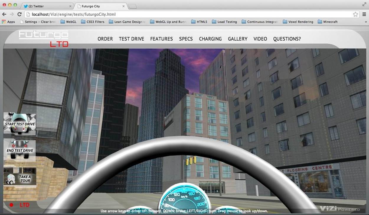
Figure 11-13. View from a camera placed inside the Futurgo vehicle
Example 11-14 shows the code to create the second camera. First, we create a new Vizi.Object, driveCam, to hold the camera component. driveCam will be added as a child of the Futurgo car. Why? So that when the car moves—we’ll get to this in a few pages—the camera will move along with it. Remember the discussion of the transformation hierarchy in earlier chapters: the transform properties of an object (position, rotation, scale) affect the transforms of its children. Whenever the car moves or turns, the camera comes along for the ride.
Next, we position the camera within the vehicle. Adding it as a child of the Futurgo places it at the car’s origin by default; in this case, that means the camera would end up on the ground. So we place it appropriately. However, we have to do something a little gross to position it: when TC modeled the Futurgo, he left a scale value in there. (I verified this by loading the model into the previewer and checking the scale values of the top-level group.) Rather than ask TC to labor through rescaling the model, I simply adjusted the positional values of the camera to compensate for it by dividing the desired values by the scale of each dimension. The result is a camera positioned at eye level for a seated driver who is approximately six feet tall, as depicted in Figure 11-13.
Example 11-14. Creating the drive camera
// Drop a camera inside the vehicle
var driveCam = new Vizi.Object;
var camera = new Vizi.PerspectiveCamera;
camera.near = 0.01;
driveCam.addComponent(camera);
futurgo.addChild(driveCam);
// Account for scale in model so that
// we can position the camera properly
var scaley = futurgo.transform.scale.y;
var scalez = futurgo.transform.scale.z;
var camy = FuturgoCity.AVATAR_HEIGHT_SEATED / scaley;
var camz = 0 / scalez;
driveCam.transform.position.set(0, camy, camz);
this.driveCamera = camera;
In the next section, I will show you how to switch to this camera, as part of a sequence of transitions to get in and out of the car to start and stop test-drive mode.
Creating Timed and Animated Transitions
We’re getting close to being able to take our test drive. Clicking on the Futurgo with the mouse, or clicking the Start Test Drive tab on the left, pops us inside the car so that we can drive. In order to make this fun and a somewhat real-feeling experience, we will program a series of transitions and animations using a combination of Vizi components and simple timers based on setTimeout().
The sequence, implemented in the code listed in Example 11-15 and subsequent code fragments, is as follows:
1. Disable picking from inside the car. We don’t want stray mouse clicks to trigger unwanted animations.
2. Open the car by animating the windows out.
3. After the window open animation finishes, jump inside the car.
4. Once inside the car, close the windows and fade them to fully transparent so that we can see outside. Also turn down the volume of the city background sound. Finally, enable the scripts that drive the car.
After performing the preceding sequence, we will be inside the car and ready to drive. Let’s look at the code step by step.
First, we turn off the pickers and start the open animations.
Example 11-15. Animating transitions to enter the car and start test drive
FuturgoCity.prototype.startTestDrive = function(event) {
if (this.testDriveRunning)
return;
this.testDriveRunning = true;
// Disable the pickers while inside the car body
var i, len = this.pickers.length;
for (i = 0; i < len; i++) {
this.pickers[i].enabled = false;
}
// Open the car windows
this.playOpenAnimations();
After a one-second delay we do the next step: jump to the driveCamera view. We do this by setting the camera’s active property to true (which, under the covers, tells Vizi to render using this new camera). We also disable the first-person camera controller’s ability to move by setting itsmove property to false. We still want to be able to look around, so we continue to use the first-person controller for that: while inside the car, we will be able to use the mouse to tilt and turn the camera orientation.
// After opening the car, move to the inside camera
// and activate the controller for test drive - on a
// delay
var that = this;
setTimeout(function() {
// Switch to the car interior camera
that.cameraController.camera = that.driveCamera;
// Don't allow camera move, we want to
// stay in the car
that.cameraController.move = false;
that.driveCamera.rotation.set(0, 0, 0);
that.driveCamera.active = true;
}, 1000);
Now we are settled in the car, looking out from the seat. Let’s trigger another sequence to close it, a second later. We play the animations to close the windows. We also lower the volume of the exterior sounds (later in the chapter, we will discuss adding sound to the application). We fade the windows to almost completely transparent, so that we can see out. Finally, we enable the scripts that drive the car and animate the dashboard. Now we are ready to roll.
// Now that we're inside, enable the car controller
// Also shut the windows and fade them
// to nearly transparent so we can see the city
setTimeout(function() {
// Close the car windows
that.playCloseAnimations();
// Dampen city background sounds
that.sound.interior();
// Fade the windows
var i, len = that.faders.length;
for (i = 0; i < len; i++) {
var fader = that.faders[i];
fader.opacity = FuturgoCity.OPACITY_MOSTLY_TRANSPARENT;
fader.start();
}
// Enable the car scripts - controller and dashboard animations
that.carController.enabled = true;
that.dashboardScript.enabled = true;
}, 2000);
The code to exit test-drive mode, in method endTestDrive(), not shown here, essentially reverses the previous steps:
1. Disable the car scripts.
2. Open the windows.
3. Re-enable the pickers; jump the camera back to outside view; re-enable move mode in the camera controller; restore the outside sound to full volume; fade the windows back to semi-opaque.
4. Close the windows.
Scripting Object Behaviors
Now it is time to make the car move. To do that, we will write a controller similar in style to the first-person controller used for walking around in the scene. In this case, the keyboard moves and turns the car instead of the camera. (We still want to have the mouse tilt and turn the view, so we will continue to use the existing camera controller for that, but we will connect the interior camera driveCamera to it, as described in the previous section.) To create the controller, we are going to build a custom component using the Vizi framework.
Implementing Custom Components Based on Vizi.Script
Ultimately, Vizi derives its power from the combination of two simple ideas: 1) a set of code created to handle common 3D design patterns (e.g., start/stop an action, find an object under the mouse, switch a camera), and 2) the ability to plug things together and have the parts interoperate. Vizi components can work with virtually any object because objects are organized consistently and follow a few simple rules. For example, each Vizi.Object instance contains a transform component with position, rotation, and scale properties that the other components of the object can manipulate.
The prefabs discussed earlier in this chapter, such as Vizi.Prefabs.Skybox() and Vizi.Prefabs.FirstPersonController(), are functions that create a hierarchy of prebuilt objects and return a Vizi.Object as the root of the newly created hierarchy. The object could be a single, simple thing that just contains, say, a cube; on the other hand, it could be a complex hierarchy consisting of several objects and components. Prefabs that contain anything other than dumb geometry will likely also have one or more scripts that implement the logic for the prefab. For example, the Vizi skybox prefab contains cube geometry, as well as a script responsible for matching the orientation of the skybox to the orientation of the main camera in the scene.
For the Futurgo city application, we need to create a script that drives the car. If we make this script a Vizi component and simply add it to the Futurgo car object, the Vizi framework will make sure its update() method is called each time through the run loop, giving it a chance to respond to user input and move the car accordingly. Let’s look at how to build it.
A Controller Script to Drive the Car
Recall the code that handled initializing the car after the model was loaded. It added picker components, faders, and so on, and added environment maps. It also did this:
// Add the car controller
this.carController = new FuturgoController({enabled:false,
scene: this.scene});
futurgo.addComponent(this.carController);
FuturgoController is a component created to do one job: drive the car using the arrow keys. The up arrow accelerates the car forward; the down arrow applies the brakes; the left and right arrows turn it. The controller also tests for collision to keep the car from driving through walls, and it follows the terrain so that the car drives up and onto curbs or other elevated features, rather than “plowing” through them. And because we placed the driveCamera camera inside the car, thanks to the magic of the transform hierarchy, the camera will move as the car moves, so we can enjoy the ride.
Let’s look at the code that implements this controller (Example 11-16). The source file is located in Chapter 11/futurgoController.js. The constructor function first subclasses Vizi.Script, the base type for any script components used by the framework. It then initializes several properties: the state of movement keys, the current speed and acceleration, a few bookkeeping variables that will help support the collision and terrain-following algorithms, and several timestamps to help implement the pseudophysics algorithms we will use to control the speed of the car.
Example 11-16. Constructor for the FuturgoController component
FuturgoController = function(param)
{
param = param || {};
Vizi.Script.call(this, param);
this.enabled = (param.enabled !== undefined) ? param.enabled : true;
this.scene = param.scene || null;
this.turnSpeed = Math.PI / 2; // 90 degs/sec
this.moveForward = false;
this.moveBackward = false;
this.turnLeft = false;
this.turnRight = false;
this.accelerate = false;
this.brake = false;
this.acceleration = 0;
this.braking = 0;
this.speed = 0;
this.rpm = 0;
this.eyePosition = new THREE.Vector3;
this.downVector = new THREE.Vector3(0, −1, 0);
this.groundY = 0;
this.avatarHeight = FuturgoCity.AVATAR_HEIGHT_SEATED;
this.savedPos = new THREE.Vector3;
this.movementVector = new THREE.Vector3;
this.lastUpdateTime = Date.now();
this.accelerateStartTime = this.brakeStartTime =
this.accelerateEndTime = this.brakeEndTime =
this.lastUpdateTime;
}
Vizi components usually implement two methods: realize() and update(). realize() is called by the framework when it’s time to create the data structures required for rendering, input, networking, or other browser-supplied services. For the car controller, realize() does two things: save the initial position of the car, and create a bounce behavior that will be triggered when the car collides with something. The car is accessed via the property this._object, which Vizi automatically sets on a component when it is added to an object.
FuturgoController.prototype.realize = function()
{
this.lastUpdateTime = Date.now();
// Save ground position
this.groundY = this._object.transform.position.y;
// Add a bounce behavior to run on collide
this.bouncer = new Vizi.BounceBehavior(
{ duration : FuturgoController.BOUNCE_DURATION }
);
this._object.addComponent(this.bouncer);
}
Now for update(): this method is called for every component of every object in the Vizi scene graph, each time through the application’s run loop. For the car controller, update() has to do several things. First, it saves the current position of the car, which will be used to restore it if there is a collision or if we need to move up or down to follow the terrain. Then, it updates the speed based on its internal physics algorithm. After that, it uses the speed property to calculate a new position. Finally, it tests for collision and terrain following.
FuturgoController.prototype.update = function()
{
if (!this.enabled)
return;
var now = Date.now();
var deltat = now - this.lastUpdateTime;
this.savePosition();
this.updateSpeed(now, deltat);
this.updatePosition(now, deltat);
this.testCollision();
this.testTerrain();
this.lastUpdateTime = now;
}
Updating the speed involves using a simple pseudophysics algorithm that fakes acceleration and momentum; see Example 11-17. The longer the up arrow key is pressed, the more acceleration increases; the longer the down arrow key is pressed, the more the brakes are applied and the car slows down. If no keys are pressed, there will still be a certain amount of momentum applied if the car was already traveling forward. After these computations, if either the speed or acceleration changes, we also dispatch events to tell listeners that the speed has changed. The dashboard controller (covered later in the chapter) will use that information to change the speed and RPM represented on its dials.
Example 11-17. Updating the car speed
FuturgoController.prototype.updateSpeed = function(now, deltat) {
var speed = this.speed, rpm = this.rpm;
// Accelerate if the pedal is down
if (this.accelerate) {
var deltaA = now - this.accelerateStartTime;
this.acceleration = deltaA / 1000 * FuturgoController.ACCELERATION;
}
else {
// Apply momentum
var deltaA = now - this.accelerateEndTime;
this.acceleration -= deltaA / 1000 * FuturgoController.INERTIA;
this.acceleration = Math.max( 0, Math.min( FuturgoController.MAX_ACCELERATION,
this.acceleration) );
}
speed += this.acceleration;
// Slow down if the brake is down
if (this.brake) {
var deltaB = now - this.brakeStartTime;
var braking = deltaB / 1000 * FuturgoController.BRAKING;
speed -= braking;
}
else {
// Apply inertia
var inertia = deltat / 1000 * FuturgoController.INERTIA;
speed -= inertia;
}
speed = Math.max( 0, Math.min( FuturgoController.MAX_SPEED, speed ) );
rpm = Math.max( 0, Math.min( FuturgoController.MAX_ACCELERATION,
this.acceleration ) );
if (this.speed != speed) {
this.speed = speed;
this.dispatchEvent("speed", speed);
}
if (this.rpm != rpm) {
this.rpm = rpm;
this.dispatchEvent("rpm", rpm);
}
}
To update the position of the car, we use the current speed to move along the line of sight (negative z-axis). We also turn the car by rotating the object around its y-axis.
FuturgoController.prototype.updatePosition = function(now, deltat) {
var actualMoveSpeed = deltat / 1000 * this.speed;
var actualTurnSpeed = deltat / 1000 * this.turnSpeed;
// Translate in Z...
this._object.transform.object.translateZ( -actualMoveSpeed );
// ...but keep the vehicle on the ground
this._object.transform.position.y = this.groundY;
// Turn
if ( this.turnLeft ) {
this._object.transform.object.rotateY( actualTurnSpeed );
}
if ( this.turnRight ) {
this._object.transform.object.rotateY( -actualTurnSpeed );
}
}
Detecting collisions between the car and scene
The code to detect collisions between the car and buildings is similar to the code used in Vizi.FirstPersonController. It calls the graphics system’s objectFromRay() method to calculate the intersection of the ray from the current camera position to the desired one, and any geometry in the scene. Note the first argument passed to objectFromRay(): this.scene contains all the geometry in the city scene, but it does not include the car itself. If we included the car’s geometry in the collision test, well, it would always return true.
FuturgoController.prototype.testCollision = function() {
this.movementVector.copy(this._object.transform.position)
.sub(this.savedPos);
this.eyePosition.copy(this.savedPos);
this.eyePosition.y = this.groundY + this.avatarHeight;
var collide = null;
if (this.movementVector.length()) {
collide = Vizi.Graphics.instance.objectFromRay(this.scene,
this.eyePosition,
this.movementVector,
FuturgoController.COLLISION_MIN,
FuturgoController.COLLISION_MAX);
if (collide && collide.object) {
var dist = this.eyePosition.distanceTo(collide.hitPointWorld);
}
}
if (collide && collide.object) {
this.handleCollision(collide);
}
}
Implementing collision response
In our walk through the city, the first-person controller kept us from passing through solid buildings. Whenever a collision happened, we stopped dead. For the car, we would like to do something a little subtler. In the real world, when a car hits a building, it’s going to bounce, if not crash. In our easygoing simulation, we want to have the Futurgo bounce softly when it collides with something in the scene. The concept of how a 3D application behaves when objects collide is known as collision response.
Example 11-18 shows how the bounce collision response is implemented in the car controller. First, we dispatch a “collide” event to any listeners. The application will be listening for this to trigger a sound when the car collides. Then, we reset the car’s position to its original value so that it doesn’t pass through the geometry, by calling restorePosition(). Next, recall that the realize() method added a Vizi.BounceBehavior component to the car. We trigger that bounce behavior, which makes the car bounce backward a bit. Backward here means in the opposite direction of movement; see how we set the bounder’s bounceVector property to the negative of the movement vector, and scale it down to a third to simulate that some of the force of movement was absorbed on “impact.” Finally, we kill the motor.
Example 11-18. Handling collision with a collision response
FuturgoController.prototype.handleCollision = function(collide) {
// Tell any listeners
this.dispatchEvent("collide", collide);
// Move back to previously saved position
this.restorePosition();
// Run the bounce response
this.bouncer.bounceVector
.copy(this.movementVector)
.negate()
.multiplyScalar(.333);
this.bouncer.start();
// Kill the motor
this.speed = 0;
this.rpm = 0;
}
Implementing terrain following
The city environment is pretty flat, but there are a couple of bits of elevation. The curb rests above street level. We need to decide what to do when the Futurgo drives up to it. It could either stop, or climb up onto the curb. What we don’t want to happen is for the car to “plow” through the curb, driving through it like it wasn’t there. Stopping at the point it hits the pavement would be easy, but not much fun. Instead, we are going to have the car drive up and onto the curb. To do that, we need to implement terrain following.
Terrain following refers to algorithms that keep the camera or avatar at a constant distance above the ground. As the camera moves within the scene, a ray is cast downward. If it collides with any geometry, the distance is checked against the desired height of the camera. If the distance is less than the desired value, the camera is moved upward, seemingly “stepping” up; if the distance is greater than the desire value, the camera is moved down.
The Futurgo car controller performs a terrain following check each time through its update method. Once again, we’ll use the Vizi methods to test collision against the scene geometry, but this time with a ray pointing downward (downVector = [0, −1, 0]). Try it out for yourself. Drive toward a building, and the car will climb up onto the curb. Drive back toward the street, and it will climb back down to the pavement. See the code in Example 11-19, and the illustration of collision and terrain following in Figure 11-14.
Example 11-19. Terrain following in the Futurgo
FuturgoController.prototype.testTerrain = function() {
var EPSILON = 0.00001;
var terrainHit = Vizi.Graphics.instance.objectFromRay(this.scene,
this.eyePosition,
this.downVector);
if (terrainHit && terrainHit.object) {
var dist = this.eyePosition.distanceTo(terrainHit.hitPointWorld);
var diff = this.avatarHeight - dist;
if (Math.abs(diff) > EPSILON) {
console.log("distance", dist);
this.eyePosition.y += diff;
this._object.transform.position.y += diff;
this.groundY = this._object.transform.position.y;
}
}
}
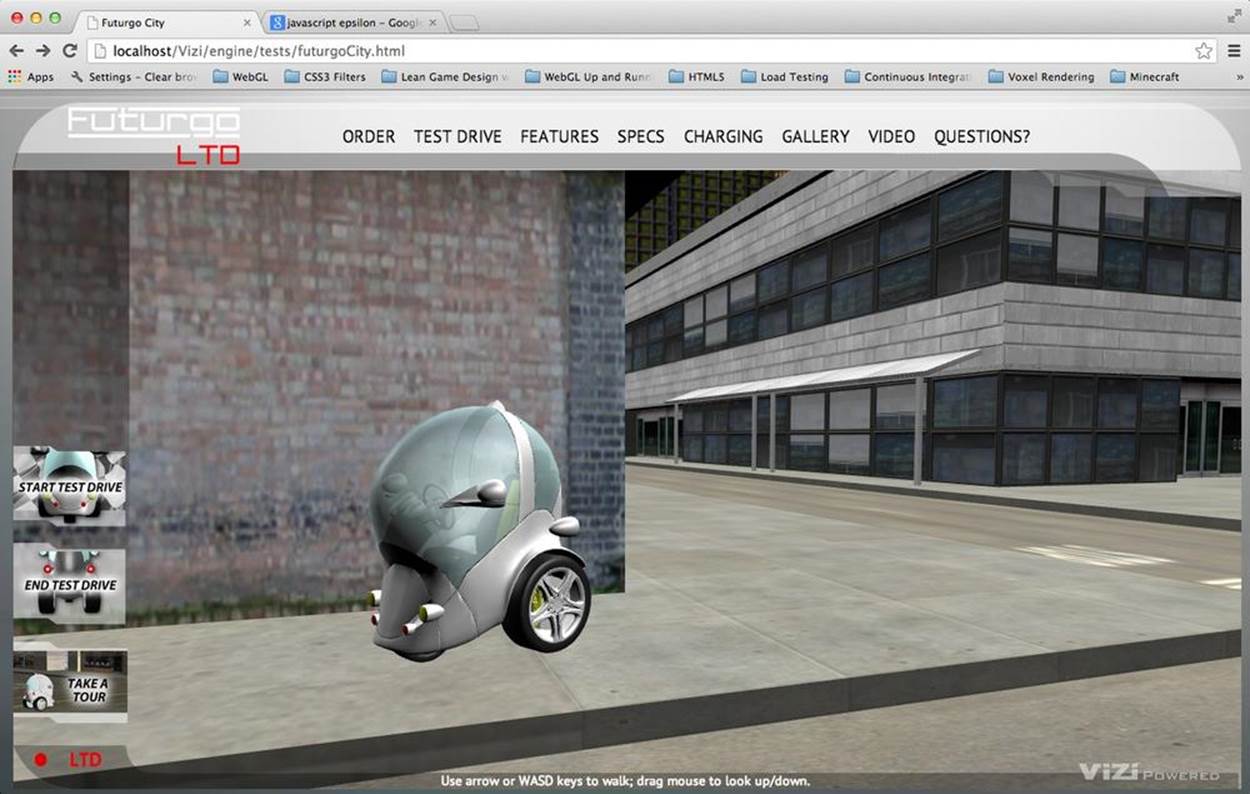
Figure 11-14. Collision and terrain following: the car stops at walls and drives up onto sidewalk using ray casting
Adding Sound to the Environment
This is getting pretty fun—blazing through city streets in our Car of the Future—but something is missing: sound. Sound might be a luxury in page-based web applications, but in a realistic 3D environment, its absence is all too conspicuous. Thankfully, it is easy to add basic sounds using standard HTML5 audio.
For this application, we need only two sounds: a looped ambient sound for the city background, and a short sound to make a “bump” noise when the car collides with something. First, we add <audio> and <sound> elements to the HTML page (file Chapter 11/futurgoCity.html):
<audio volume="0.0" id="city_sound">
<!-- http://www.freesound.org/people/synthetic-oz/sounds/162704/ -->
<source src="../sounds/162704__synthetic-oz__city-trimmed-looped.wav"
type="audio/wav" />
Your browser does not support WAV files in the audio element.
</audio>
<audio volume="0.0" id="bump_sound">
<!-- http://www.freesound.org/people/Calethos/sounds/31126/ -->
<source src="../sounds/31126__calethos__bump.wav" type="audio/wav" />
Your browser does not support WAV files in the audio element.
</audio>
Now we just need to write a little code to change volumes and trigger sound playback. When we go inside the Futurgo for the test drive, the city sound volume should be lowered; when we step out, we should hear the city at full volume again. When we collide, the bump sound should play once.
Sound is implemented in the source file Chapter 11/futurgoSound.js. It is quite simple, using standard HTML5 DOM audio methods. Example 11-20 shows the code in its entirety. The methods interior() and exterior() raise and lower the ambient background sound, respectively. The method bump() plays the bump sound once.
Example 11-20. Managing sounds in the Futurgo city scene
FuturgoSound = function(param) {
this.citySound = document.getElementById("city_sound");
this.citySound.volume = FuturgoSound.CITY_VOLUME;
this.citySound.loop = true;
this.bumpSound = document.getElementById("bump_sound");
this.bumpSound.volume = FuturgoSound.BUMP_VOLUME;
}
FuturgoSound.prototype.start = function() {
this.citySound.play();
}
FuturgoSound.prototype.bump = function() {
this.bumpSound.play();
}
FuturgoSound.prototype.interior = function() {
$(this.citySound).animate(
{volume: FuturgoSound.CITY_VOLUME_INTERIOR},
FuturgoSound.FADE_TIME);
}
FuturgoSound.prototype.exterior = function() {
$(this.citySound).animate(
{volume: FuturgoSound.CITY_VOLUME},
FuturgoSound.FADE_TIME);
}
FuturgoSound.prototype.bump = function() {
this.bumpSound.play();
}
FuturgoSound.CITY_VOLUME = 0.3;
FuturgoSound.CITY_VOLUME_INTERIOR = 0.15;
FuturgoSound.BUMP_VOLUME = 0.3;
FuturgoSound.FADE_TIME = 1000;
The only thing left to do is to wire these methods into the application. Recall the action sequence from startTestDrive() (file Chapter 11/futurgoCity.js):
// Dampen city background sounds
that.sound.interior();
Exiting the car calls exterior() to restore the sound to its original volume.
The FuturgoCity class also handles the collision sound, by adding an event listener to the car controller:
this.carController.addEventListener("collide", function(collide) {
that.sound.bump();
});
Rendering Dynamic Textures
We have reached the final leg of our tour through creating a realistic environment. The car is now ready to roll. After implementing the sound, I thought I was all done writing code. But when I jumped in to take the car for a drive, it felt lifeless. I quickly realized that’s because the dials on the control panel were dead—the dials on the speedometer and tachometer gauges didn’t move when the car did. As was the case with sound, the realism of the environment created elevated expectations on my part. If the car is moving, the dials have to spin, too. So, we needed to animate the dashboard—or at least, its texture map.
In this section, we are going to create a procedural texture; that is, a texture map drawn dynamically from program code (versus a static image loaded from a file). To do that, we turn to an old standby: 2D canvas rendering. The dashboard uses the 2D Canvas API to generate a procedural texture representing the current speed and RPM values on the gauges.
The original dashboard texture map on the Futurgo came with dials in fixed positions. I asked TC to split the dial out from the rest of the dashboard as a separate image. He did that and gave me the sliced images. TC didn’t need to change the 3D art, just the textures. The two bitmap files are depicted in Figures 11-15 and 11-16.
To do the dashboard animation, we are going to create another Vizi custom component, FuturgoDashboard. It is a script that creates an HTML Canvas element, loads the two bitmaps during realize(), and updates the dials during update() based on the current speed and RPM. We will track the speed and RPM by adding event listeners to the FuturgoController.
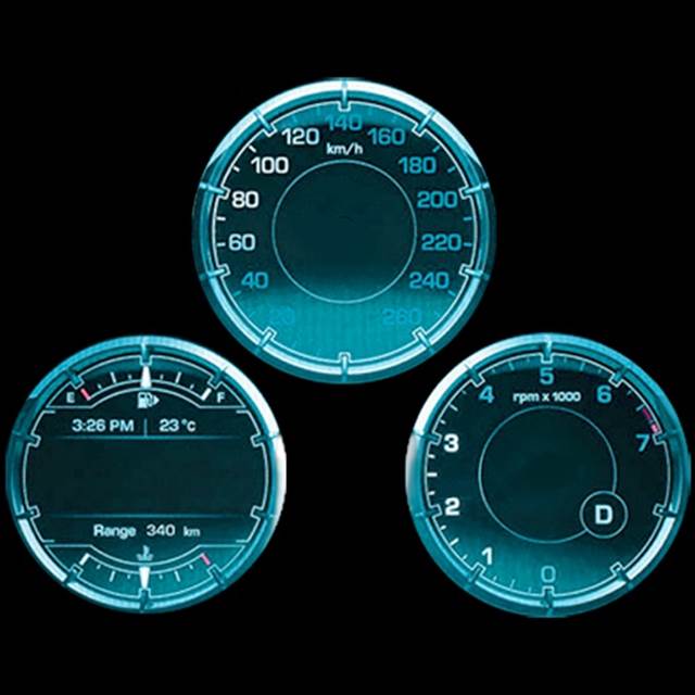
Figure 11-15. Texture map for the dashboard gauges
![]()
Figure 11-16. Texture map for the rotatable dial
Example 11-21 shows how we set this up. realize() creates a new Canvas element, and a Three.js texture object to hold it. We then set that new texture as the map property of the dashboard’s material. Later, we can use standard Canvas 2D drawing API calls to update the contents of the canvas, and those changes will be reflected in the texture map on the object.
Example 11-21. Creating a canvas texture for the dashboard
FuturgoDashboardScript.prototype.realize = function()
{
// Set up the gauges
var gauge = this._object.findNode("head_light_L1");
var visual = gauge.visuals[0];
// Create a new canvas element for drawing
var canvas = document.createElement("canvas");
canvas.width = 512;
canvas.height = 512;
// Create a new Three.js texture with the canvas
var texture = new THREE.Texture(canvas);
texture.wrapS = texture.wrapT = THREE.RepeatWrapping;
visual.material.map = texture;
this.texture = texture;
this.canvas = canvas;
this.context = canvas.getContext("2d");
Continuing with realize(), here is the code to load the textures. We use DOM properties to do this: first, set an onload hander, which will tell us when the image is loaded and ready. Then, we set the src property to load the image.
// Load the textures for the dashboard and dial
this.dashboardImage = null;
this.dialImage = null;
var that = this;
var image1 = new Image();
image1.onload = function () {
that.dashboardImage = image1;
that.needsUpdate = true;
}
image1.src = FuturgoDashboardScript.dashboardURL;
var image2 = new Image();
image2.onload = function () {
that.dialImage = image2;
that.needsUpdate = true;
}
image2.src = FuturgoDashboardScript.dialURL;
// Force an initial update
this.needsUpdate = true;
}
It’s time to draw; see Example 11-22. Each time through the dashboard script’s update() method, we will test whether we need to redraw the texture, based on whether the speed or RPM value of the car controller has changed. If it has, we call draw() to apply the Canvas API drawing to the texture. draw() begins by clearing the contents of the canvas with the current text color. Then, if the dashboard bitmap has been loaded, it draws that to the canvas using the context’s drawImage() method, covering the entire canvas with the pixels from the image.
Example 11-22. Drawing the background dashboard image
FuturgoDashboardScript.prototype.draw = function()
{
var context = this.context;
var canvas = this.canvas;
context.clearRect(0, 0, canvas.width, canvas.height);
context.fillStyle = this.backgroundColor;
context.fillRect(0, 0, canvas.width, canvas.height);
context.fillStyle = this.textColor;
if (this.dashboardImage) {
context.drawImage(this.dashboardImage, 0, 0);
}
NOTE
If you are rusty on the Canvas API, Chapter 7 covers the basics of Canvas drawing.
Now, we need to draw the dial on top. We have been keeping track of the car’s speed and tachometer (more on this in a bit); we use those values to calculate an angle of rotation for the dial bitmap. Recall that the 2D Canvas API provides methods, save() and restore(), for saving the current state of the context before a set of drawing calls, and restoring to that state after doing the drawing. We’ll bracket the drawing of each dial with those calls. After saving state, we perform 2D transforms on the context, translating the dial bitmap we are about to draw to the correct position on the gauge, and rotating it by the right amount to match the current speed and RPM values. Then, we draw the image and restore the context. We do this for each gauge. (I figured out the translation values used here based on the size of the dial bitmap, and a location I was able to determine by messing around in an image editing program.)
var speeddeg = this._speed * 10 - 120;
var speedtheta = THREE.Math.degToRad(speeddeg);
var rpmdeg = this._rpm * 20 - 90;
var rpmtheta = THREE.Math.degToRad(rpmdeg);
if (this.dialImage) {
context.save();
context.translate(FuturgoDashboardScript.speedDialLeftOffset,
FuturgoDashboardScript.speedDialTopOffset);
context.rotate(speedtheta);
context.translate(-FuturgoDashboardScript.dialCenterLeftOffset,
-FuturgoDashboardScript.dialCenterTopOffset);
context.drawImage(this.dialImage, 0, 0);
context.restore();
context.save();
context.translate(FuturgoDashboardScript.rpmDialLeftOffset,
FuturgoDashboardScript.rpmDialTopOffset);
context.rotate(rpmtheta);
context.translate(-FuturgoDashboardScript.dialCenterLeftOffset,
-FuturgoDashboardScript.dialCenterTopOffset);
context.drawImage(this.dialImage, 0, 0); // 198, 25, 115);
context.restore();
}
}
The only thing remaining to do is to wire up the car controller to the dashboard, so that it can listen to those speed and RPM changes.
The city app sets the carController property of the dashboard after it is created:
this.dashboardScript.carController = this.carController;
carController, shown in Example 11-23, is a JavaScript property that we created using Object.defineProperties. Under the covers, setting the property results in calling the setCarController() accessor method of the object. This method saves the controller in a private property, this_carController, and adds event listeners for the car controller’s “speed” and “rpm” events. Those listeners save the new values, and flag that the dashboard needs to be redrawn by setting its needsUpdate property. Now, whenever the car speeds up or slows down, the dashboard display will redraw to reflect it.
Example 11-23. Dashboard controller script setting up listeners for car speed and RPM changes
FuturgoDashboardScript.prototype.setCarController =
function(controller) {
this._carController = controller;
var that = this;
controller.addEventListener("speed", function(speed) {
that.setSpeed(speed); });
controller.addEventListener("rpm", function(rpm) {
that.setRPM(rpm); });
}
NOTE
The power of using a Canvas element as a WebGL texture cannot be overestimated. It allows developers to use a familiar, easy API to dynamically draw textures in JavaScript, opening up possibilities for mind-blowing effects. The designers of WebGL got it right with that one. WebGL also supports HTML video element textures, making for even more potentially powerful combinations.
Chapter Summary
This was a long chapter, but it covered huge ground.
You learned how to deliver a working, realistic-looking 3D environment in a web page, with a panoramic background, environment map reflections, user-controlled navigation, sound design, and a moving object with interactive behaviors. We fortified our tool set, adding features to the previewer that allowed us to see the structure of the scene graph and detailed properties of each object. You learned to develop simplified versions of several classic 3D game algorithms and effects, such as first-person navigation, collision and terrain following, skybox rendering, and procedural textures.
Creating 3D environments in a browser is hard work, but it can be done on web time with a web budget. And now, you have a sense of what it takes to get the job done.
All materials on the site are licensed Creative Commons Attribution-Sharealike 3.0 Unported CC BY-SA 3.0 & GNU Free Documentation License (GFDL)
If you are the copyright holder of any material contained on our site and intend to remove it, please contact our site administrator for approval.
© 2016-2026 All site design rights belong to S.Y.A.